EP0629901A1 - Magasin de papier - Google Patents
Magasin de papier Download PDFInfo
- Publication number
- EP0629901A1 EP0629901A1 EP94108952A EP94108952A EP0629901A1 EP 0629901 A1 EP0629901 A1 EP 0629901A1 EP 94108952 A EP94108952 A EP 94108952A EP 94108952 A EP94108952 A EP 94108952A EP 0629901 A1 EP0629901 A1 EP 0629901A1
- Authority
- EP
- European Patent Office
- Prior art keywords
- paper
- core
- roller
- press rollers
- magazine
- Prior art date
- Legal status (The legal status is an assumption and is not a legal conclusion. Google has not performed a legal analysis and makes no representation as to the accuracy of the status listed.)
- Granted
Links
- 238000001514 detection method Methods 0.000 claims abstract description 32
- 230000005540 biological transmission Effects 0.000 claims abstract description 13
- 230000008034 disappearance Effects 0.000 claims description 3
- 238000007373 indentation Methods 0.000 abstract description 5
- 230000002093 peripheral effect Effects 0.000 description 4
- 239000002184 metal Substances 0.000 description 2
- 229910052751 metal Inorganic materials 0.000 description 2
- 230000002159 abnormal effect Effects 0.000 description 1
- 230000000295 complement effect Effects 0.000 description 1
- 238000012840 feeding operation Methods 0.000 description 1
- 150000002739 metals Chemical class 0.000 description 1
Images


Classifications
-
- G—PHYSICS
- G03—PHOTOGRAPHY; CINEMATOGRAPHY; ANALOGOUS TECHNIQUES USING WAVES OTHER THAN OPTICAL WAVES; ELECTROGRAPHY; HOLOGRAPHY
- G03D—APPARATUS FOR PROCESSING EXPOSED PHOTOGRAPHIC MATERIALS; ACCESSORIES THEREFOR
- G03D17/00—Dark-room arrangements not provided for in the preceding groups; Portable dark-rooms
-
- G—PHYSICS
- G03—PHOTOGRAPHY; CINEMATOGRAPHY; ANALOGOUS TECHNIQUES USING WAVES OTHER THAN OPTICAL WAVES; ELECTROGRAPHY; HOLOGRAPHY
- G03B—APPARATUS OR ARRANGEMENTS FOR TAKING PHOTOGRAPHS OR FOR PROJECTING OR VIEWING THEM; APPARATUS OR ARRANGEMENTS EMPLOYING ANALOGOUS TECHNIQUES USING WAVES OTHER THAN OPTICAL WAVES; ACCESSORIES THEREFOR
- G03B27/00—Photographic printing apparatus
- G03B27/32—Projection printing apparatus, e.g. enlarger, copying camera
- G03B27/52—Details
- G03B27/58—Baseboards, masking frames, or other holders for the sensitive material
- G03B27/587—Handling photosensitive webs
- G03B27/588—Supply rolls; Cutting arrangements
-
- B—PERFORMING OPERATIONS; TRANSPORTING
- B65—CONVEYING; PACKING; STORING; HANDLING THIN OR FILAMENTARY MATERIAL
- B65H—HANDLING THIN OR FILAMENTARY MATERIAL, e.g. SHEETS, WEBS, CABLES
- B65H16/00—Unwinding, paying-out webs
-
- G—PHYSICS
- G03—PHOTOGRAPHY; CINEMATOGRAPHY; ANALOGOUS TECHNIQUES USING WAVES OTHER THAN OPTICAL WAVES; ELECTROGRAPHY; HOLOGRAPHY
- G03B—APPARATUS OR ARRANGEMENTS FOR TAKING PHOTOGRAPHS OR FOR PROJECTING OR VIEWING THEM; APPARATUS OR ARRANGEMENTS EMPLOYING ANALOGOUS TECHNIQUES USING WAVES OTHER THAN OPTICAL WAVES; ACCESSORIES THEREFOR
- G03B27/00—Photographic printing apparatus
- G03B27/32—Projection printing apparatus, e.g. enlarger, copying camera
- G03B27/46—Projection printing apparatus, e.g. enlarger, copying camera for automatic sequential copying of different originals, e.g. enlargers, roll film printers
-
- G—PHYSICS
- G03—PHOTOGRAPHY; CINEMATOGRAPHY; ANALOGOUS TECHNIQUES USING WAVES OTHER THAN OPTICAL WAVES; ELECTROGRAPHY; HOLOGRAPHY
- G03C—PHOTOSENSITIVE MATERIALS FOR PHOTOGRAPHIC PURPOSES; PHOTOGRAPHIC PROCESSES, e.g. CINE, X-RAY, COLOUR, STEREO-PHOTOGRAPHIC PROCESSES; AUXILIARY PROCESSES IN PHOTOGRAPHY
- G03C3/00—Packages of films for inserting into cameras, e.g. roll-films, film-packs; Wrapping materials for light-sensitive plates, films or papers, e.g. materials characterised by the use of special dyes, printing inks, adhesives
Definitions
- This invention relates to a paper magazine for feeding and rewinding a photographic paper from and into a roll of paper rotatably mounted thereon and used e.g. to feed a web of photographic paper to a photographic printing apparatus.
- a photographic printing apparatus has a light source 81 that emits light through a mirror tunnel 82 at a negative film 84 on a negative mask 83 to print the negative images on the negative film 84 through a printing lens 85 onto photographic paper P on an exposure unit 86.
- This conventional photographic printing apparatus B carries a plurality of paper magazines A, A' accommodating a roll R of photographic paper P having different print sizes from each other.
- the photographic paper P in one of the paper magazines A is pulled out to the exposure unit 86 for printing.
- the photographic paper in the other paper magazine A' is pulled out.
- a cutter device 87 disposed in the feed path of photographic paper extending from the paper magazine A to the exposure unit 86 is activated to cut the photographic paper P. Then, the portion of the photographic paper P that protrudes from the paper magazine A is rewound into it. Then, the photographic paper P in the other paper magazine A' is pulled out until its tip is caught between a pair of advance rollers 54 provided in the paper feed path.
- Such conventional paper magazines for feeding and rewinding photographic paper come in two types, that is, the type having a built-in feeding and rewinding mechanism and the type having no such mechanism.
- photographic paper is put in the magazine with its tip protruding slightly from the magazine.
- the magazine is then set in the photographic printing apparatus B with the protruding end of the paper caught between the advance rollers 54.
- a paper magazine of the former type has a feed roller adapted to be pressed against the photographic paper and provided near the paper outlet of the paper magazine. By manually controlling a knob coupled to the feed roller, the photographic paper is fed and rewound.
- a paper magazine having the feeding/rewinding mechanism has a problem in that since the feed rollers are always pressed against the photographic paper, it is likely to develop indentations and surface irregularity. Also, when feeding, the paper is likely to meander.
- the paper is rewound onto the core of the paper roll in the magazine by rotating the core itself.
- the paper rear end should come off the core of the paper roll, it becomes impossible to rewind paper further. This means that the entire part of the paper in the feed path in the magazine is wasted.
- It is an object of this invention is to provide a paper magazine which can feed and rewind paper automatically by supplying the driving force from outside and which can prevent indentations on the paper or meandering while being fed.
- Another object of this invention is to provide a paper magazine which can reliably rewind paper even if its rear end should come off the core of the paper roll.
- a paper magazine comprising a paper magazine case for rotatably supporting a core of a paper roll of paper, the paper magazine case being formed with a paper outlet, a pair of press rollers provided along a paper feed path extending from the core to the paper outlet and adapted to be pressed against and separated from each other with the paper therebetween, a paper detection roller provided between the press rollers and the paper outlet so as to be moved when brought into contact with the paper, a cam mechanism associated with the paper detection roller for pressing and separating the press rollers against and from each other according to the position of the paper detection roller, power transmission means coupled to the core of the paper roll and the press rollers for transmitting thereto the rotation of an external driving means, and changeover means provided in the power transmission means for selectively transmitting the driving force to the core or the press rollers according to the direction of rotation of the external driving means, whereby the press rollers are pressed against each other with the paper therebetween when the core is rotated in a direction to
- the press rollers when feeding paper, the press rollers are pressed against the paper to feed the paper.
- the position of the paper is detected by detecting the position of the paper detection roller provided between the paper outlet and the press rollers. Based on the result of detection, the cam mechanism is activated to press or separate the press rollers against or from each other and thus to control the stop position of the paper when rewinding.
- the direction of transmission of driving force i.e. to the core or the press rollers, is changed over by the power changeover means.
- the press rollers are brought into contact with the paper only while the paper is being fed and otherwise kept out of contact with the paper, the paper will be free from indentations and surface irregularity. Also, it will never meander while being fed.
- the rewinding of the paper is stopped when the paper detection roller displaces as a result of disappearance of the paper.
- the mounting position of the paper detection roller it is possible to freely adjust the position of the paper leading end when the rewinding is stopped. In other words, there is no restriction as to the length by which the paper is rewound.
- the cam mechanism comprises means for pressing the press rollers against each other with the paper therebetween when the core is rotated in a direction for rewinding the paper, and means for keeping the press rollers pressed against each other irrespective of the position of the paper detection roller.
- the press rollers are pressed against the paper when rewinding paper.
- the paper can be forcibly rewound onto the core in the magazine.
- the press rollers since the press rollers are kept pressed against the paper with the paper fully rewound, the paper can be held in position stably even if the magazine is vibrated such as while being carried.
- the paper magazine according to this invention is provided with a roller for detecting the position of the paper while it is being fed or rewound, a cam mechanism operatively associated with the paper detection roller to control the movement of the press rollers, and a power transmission means for selectively transmitting and cutting off the driving force to the core and the press rollers.
- the press rollers are pressed against paper only when feeding it.
- the paper can be fed accurately and stably without meandering and without the possibility of indentation or surface irregularity.
- the concept of this invention is applicable to other types of devices having different paper feed paths.
- the press rollers are pressed against the paper when rewinding it, it is possible to feed and rewind paper without leaving any part of the paper in the magazine and thus to eliminate any loss of paper.
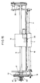
- a paper magazine case 1 consists of two portions. It can be opened and closed by pivoting one of the two portions about a pin 2.
- a paper outlet 3 is defined in the lower portion of the front side of the case 1.
- a support shaft 4 is provided in the central portion of the paper magazine case 1.
- a core 5 of a roll R of photographic paper P is rotatably mounted on the support shaft 4.
- the photographic paper P is pulled out from the roll R to a guide roller 6 provided in the front part of the paper magazine case 1 and then to the paper outlet 3.
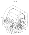
- a pair of front and rear press rollers 7, 8 (Fig. 3).
- the rear large-diameter roller 8 (hereinafter referred to as a feed roller) is mounted integrally to a rotary shaft 9 that extends through the paper magazine 1.
- the front small-diameter roller 7 (hereinafter referred to as a press roller) is mounted on a roller shaft 10 at its center.
- the roller shaft 10 has its both ends extending through holes 12 formed in a pair of support plates 11 provided spaced apart a predetermined distance from the inner surfaces of the side plates of the paper magazine case 1.
- the holes 12 are elongated in the back-to-forth direction, so that the roller shaft 10 is movable back and forth.
- the roller shaft 10 carries a pair of grooved metals 13 at points inside the support plates 11.
- a spring 15 fits in a peripheral groove 14 of each metal 13 and has its both ends fixed to the respective support plate 11. The roller shaft 10 is thus urged rearwards by the springs 15, so that the press roller 7 is pressed against the feed roller 8.
- the roller shaft 10 is provided parallel to the rotary shaft 9, which carries the feed roller 8, and carries at its one end an engaging roller 16 which forms a cam mechanism in cooperation with a cam plate 17 mounted on one end of the rotary shaft 9 so as to be located opposite to the engaging roller 16.
- the engaging roller 16 is axially slidably mounted on a guide shaft 18 provided at the end of the roller shaft 10.
- the guide shaft 18 also carries a spring 19 to urge the engaging roller 16 to its reference position with respect to the cam plate 17.
- the cam plate 17 has an inner circular surface 20 that are kept out of contact with the engaging roller 16.
- the roller shaft 10 is urged rearwards by the springs 15 so that the press roller 7 is pressed against the feed roller 8.
- the cam plate 17 also has a cam surface 22 formed with a guide flange 21.
- the roller separating cam surface 22 has a larger diameter than the circular surface 20.
- the circular surface 20 is partially formed with a lateral feed cam surface 23 (Fig. 7) along which the engaging roller 16 is pushed up from the circular surface 20 toward the large-diameter roller separating cam surface 22.
- Adjacent the lateral feed cam surface 23 and on the side of the roller separating cam surface 22 is provided an oblique guide surface 24 along which the engaging roller 16 is adapted to be moved from the roller separating cam surface 22 toward the circular surface 20.
- a rotary actuator shaft 25 that extends parallel to the rotary shaft 9.
- Two roller restrictor plates 26, 27 are mounted on one end of the actuator shaft 25. As shown in Figs. 7 and 10, one roller restrictor plate 26 is fixedly mounted to the actuator shaft 25, while the other roller restrictor plate 27 is pivotally mounted on it.
- the actuator shaft 25 also carries a spring 28 that urges the pivotable roller restrictor plate 27 against the fixed roller restrictor plate 26.
- the actuator shaft 25 also carries on its central portion a detector arm 29 which in turn carries at its lower end a rotatable paper detection roller 30.
- the paper detection roller 30 is located in the feed path for photographic paper P that extends from the guide roller 6 to the paper outlet 3. While the photographic paper P is being fed along the feed path, the roller 30 is kept pushed backward by the photographic paper being fed. When there is no photographic paper P being fed, it will move forward.
- roller restrictor plates 26, 27, which are coupled to the roller 30 through the detector arm 29 and the actuator shaft 25, will pivot upwards or downwards as shown in Figs. 11 or 12.
- the roller restrictor plates 26, 27 pivot downwards, they are brought into contact with the inner end of the engaging roller 16 as shown in Fig. 11, thus preventing the engaging roller 16 from moving laterally toward the circular surface 20 on the cam plate 17.
- the roller restrictor plates 26, 27 pivot upwards as shown in Fig. 12
- they will move to a position where they do not interfere with the engaging roller 16.
- the engaging roller is thus pushed toward the circular surface 20 by the spring 19.
- the cam plate 17 is mounted on the rotary shaft 9 through a one-way clutch 31 as shown in Fig. 4 so as to be rotatable only in the direction of arrow A in Fig. 3.
- a feed gear 33 is mounted through a one-way clutch 32 that permits the feed gear 33 to rotate only in the direction opposite to the direction of arrow A (i.e. the direction of arrow B in Fig. 3).
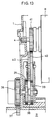
- the feed gear 33 is in meshing through a gear 34 with an intermediate gear 35 to which is coupled an input gear 36 which in turn meshes with a driving gear 37 that partially protrudes from the photographic printing apparatus B (Fig. 13).
- the input gear 36 and an advance roller 54, which will be described later, are driven by a single common motor.
- the intermediate gear 35 is coupled to a shaft 38 to which is coupled a core driving gear 39 through a one-way clutch (not shown) which permits the gear 39 to rotate only in the direction of arrow C of Fig. 3.
- the core driving gear 39 meshes with a ratcheted gear 40 that in turn meshes with one of core gears 41 coupled to the core 5.
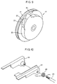
- the ratcheted gear 40 comprises a gear body and a ratchet disc 42 secured to one side of the gear body and formed with many ratchet pawls 43 along its circumference (Fig. 1).
- a locking plate 44 is coupled at one end thereof to the actuator shaft 25 so as to be pivotable toward the circumference of the ratchet disc 42.
- To the locking plate 44 is coupled a spring 45 to urge its tip into engagement with the ratchet pawl 43 at all times.
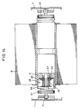
- the core gears 41 are provided inside the side walls of the paper magazine case 1 and supported on the support shaft 4, on which is rotatably mounted the core 5 of the roll R through bearings 47.
- a friction generating mechanism 48 is mounted between the support shaft 4 and the core 5. It comprises oppositely arranged friction plates 49 and 50, another friction plate 52 sandwiched between the friction plate 50 and the end face of the core 5, and a coil spring 51 that urges the friction plate 52 against the core 5 to produce a frictional resistance therebetween. Due to this frictional resistance, the core 5 is adapted to rotate together with the core gears 41.
- the paper magazine A of this embodiment is mounted on the top plate of the photographic printing apparatus B so that, as shown in Fig. 1, the paper outlet 3 of the paper magazine case 1 is located directly opposite to a paper inlet 53 of the photographic printing apparatus B.
- a pair of advance rollers 54 for feeding photographic paper P. They are adapted to rotate faster than the feed rollers 8 of the press roller pair in the paper magazine A. Near the advance rollers 54 is provided a sensor 55 for detecting the photographic paper.
- the engaging roller 16 is in contact with the roller separating cam surface 22 of the cam plate 17 as shown in Fig. 8.
- the cam plate 17 will pivot, moving the engaging roller 16 onto the circular surface 20 by way of the lateral feed cam surface 23.
- This causes the press roller 7 and the feed roller 8 to be pressed against photographic paper P. It is thus fed.
- Photographic paper P is fed by the feed roller 8 by the length corresponding to the angle by which the cam plate 17 rotates until the engaging roller 16 is again brought into contact with the lateral feed cam surface 23. Then, the engaging roller 16 is moved laterally onto the cam surface 22 by way of the lateral feed cam surface 23.
- the core 5 of the roll R While feeding photographic paper P, the core 5 of the roll R is rotated by the tensile force applied to the photographic paper P. But since the input gear 36 is rotating faster than the ratcheted gear 40, the one-way clutch for the gear 39 will disengage, so that no force is transmitted between the intermediate gear 35 and the core gears 41. In other words, the core 5 rotates with no load applied thereto.
- the advance rollers 54 will keep rotating until the leading end of the photographic paper P reaches the exposure unit 86. If the sensor 55 has not detected photographic paper P, the advance rollers 54 are rotated in a reverse direction for a predetermined period to rewind the photographic paper P until its leading end gets back to a predetermined point in the paper magazine case 1. Then, the above operation is repeated, i.e. photographic paper is fed forward again.
- This state is a normal state when rewinding.
- the core 5 is rotated under the driving force transmitted through the input gear 36 in such a direction that the photographic paper is rewound. Since the outer diameter of the roll R of the photographic paper P is greater than that of the advance rollers 54, the peripheral speed of the core 5 is higher than that of the advance rollers. Thus, there appears a difference in rotational speed between the core 5 and the core gears 41.
- the photographic paper P will be thus rewound at a speed equal to the peripheral speed of the advance rollers 54.
- the driving motor is adapted to rotate a little more after the photographic paper P has passed the sensor 55 and the locking plate 44 has engaged the ratchet pawl 43.
- the dimensions of the parts and the numbers of teeth of the respective gears are determined so that the leading end of the photographic paper P will stop between the paper detection roller 30 and the feed roller 8. With this arrangement, it is possible to transmit the driving force of the press roller 7 and the feed roller 8 to the photographic paper P when feeding it next time.
- This state is an abnormal state which may be caused by operational error.
- the feed roller 8 will rotate at the speed set for rewinding the photographic paper P under the driving force transmitted through the input gear 36.
- the photographic paper is urged by the feed force produced in the photographic printing apparatus B in such a direction as to be pulled out of the paper magazine case 1.
- slip occurs in the friction generating mechanism 48 in the core 5.
- Photographic paper P is thus pulled into the photographic printing apparatus B with back-tension being applied thereto.
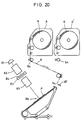
- Figs. 15 to 19 show the second embodiment.
- a torque limiter 61 is mounted which serves to transmit torque making use of frictional force.
- the torque limiter 61 comprises, as shown in Fig. 16, a presser plate 62 and a spring seat 63 mounted on the end of the rotary shaft 9, a friction plate 64 provided between the presser plate 62 and the cam plate 17, and a friction spring 65 mounted between the presser plate 62 and the spring seat 63 to bias the presser plate 62 axially and thus to press the friction plate 64 against the end face of the cam plate 17.
- the presser plate 62 and the rotary shaft 9 are prevented from rotating relative to each other by complementary flat surfaces 67 (Fig. 16B) formed on the surface of the rotary shaft 9 and on the surface of a hole 66 of the presser plate 62 through which the rotary shaft 9 extends, though they can move axially relative to each other.
- a downwardly inclined guide surface 68 through which the roller separating cam surface 22 is connected to the circular surface 20.
- a radially raised stop surface 69 is formed. The cam plate 17 is adapted to be stopped when the engaging roller 16 abuts.
- the paper When the feed roller 8 begins to rotate in the rewinding direction, the paper is fed toward the core 5 of the paper roll. Namely, the paper is rewound into the magazine and taken up onto the core 5.
- the paper Even if the rear end of the paper roll is not fastened to the core 5 or even if the remaining portion of the paper runs short and the paper rear end should come off the core 5, it is possible to rewind the paper onto the core in the magazine, so long as part of the paper remains in the paper feed path in the magazine. Then, simply by rotating the press roller and the core 5 in reverse, the paper can be fed out of the magazine. No paper will remain in the magazine and thus there will be no loss of paper.
- the engaging roller 16 is located on the circular surface 20 of the cam plate 17, so that the press rollers are pressed against the paper.
- the paper is held in place even if the paper magazine is vibrated e.g. when carrying it. This makes it possible to feed paper reliably when loading it next time.
Applications Claiming Priority (4)
| Application Number | Priority Date | Filing Date | Title |
|---|---|---|---|
| JP143561/93 | 1993-06-15 | ||
| JP14356193 | 1993-06-15 | ||
| JP89681/94 | 1994-04-27 | ||
| JP6089681A JP2932935B2 (ja) | 1993-06-15 | 1994-04-27 | ペーパマガジン |
Publications (2)
| Publication Number | Publication Date |
|---|---|
| EP0629901A1 true EP0629901A1 (fr) | 1994-12-21 |
| EP0629901B1 EP0629901B1 (fr) | 1997-09-24 |
Family
ID=26431094
Family Applications (1)
| Application Number | Title | Priority Date | Filing Date |
|---|---|---|---|
| EP94108952A Expired - Lifetime EP0629901B1 (fr) | 1993-06-15 | 1994-06-10 | Magasin de papier |
Country Status (7)
| Country | Link |
|---|---|
| US (1) | US5553809A (fr) |
| EP (1) | EP0629901B1 (fr) |
| JP (1) | JP2932935B2 (fr) |
| KR (1) | KR0185604B1 (fr) |
| CN (1) | CN1036159C (fr) |
| CA (1) | CA2125471C (fr) |
| DE (1) | DE69405813T2 (fr) |
Families Citing this family (13)
| Publication number | Priority date | Publication date | Assignee | Title |
|---|---|---|---|---|
| JP2833534B2 (ja) * | 1995-09-05 | 1998-12-09 | ノーリツ鋼機株式会社 | ペーパマガジン |
| JP3255062B2 (ja) * | 1997-01-17 | 2002-02-12 | 松下電器産業株式会社 | 電子部品装着装置 |
| JP3454348B2 (ja) * | 1998-06-12 | 2003-10-06 | 富士写真フイルム株式会社 | 感光材料の搬送装置 |
| JP3539565B2 (ja) * | 2002-02-05 | 2004-07-07 | 株式会社東京機械製作所 | 輪転機のウェブ紙保持装置 |
| DE602004024151D1 (de) * | 2003-03-05 | 2009-12-31 | Brother Ind Ltd | Kassette für einen aufgerollten Aufzeichnungsträger und Bilderzeugungsvorrichtung |
| KR100527862B1 (ko) * | 2003-06-19 | 2005-11-15 | 노경옥 | 생활 폐기물과 소성암석 분말을 이용한 유기질 비료의제조방법 |
| JP2006349797A (ja) * | 2005-06-14 | 2006-12-28 | Noritsu Koki Co Ltd | ペーパーマガジン |
| JP2011110813A (ja) * | 2009-11-27 | 2011-06-09 | Seiko Epson Corp | 記録装置、及び、記録装置の記録媒体供給構造 |
| JP6269560B2 (ja) * | 2015-04-10 | 2018-01-31 | コニカミノルタ株式会社 | 画像形成装置および画像形成システム |
| US9986965B2 (en) * | 2016-03-11 | 2018-06-05 | Kenneth Irwin Fishberger | Stethoscope covers and dispensing system for stethoscope covers |
| KR200483194Y1 (ko) | 2016-06-02 | 2017-04-19 | 최유리 | 콘센트용 안전커버 |
| US10483007B2 (en) | 2017-07-25 | 2019-11-19 | Intouch Technologies, Inc. | Modular telehealth cart with thermal imaging and touch screen user interface |
| US10538377B1 (en) * | 2019-05-15 | 2020-01-21 | Kenneth Irwin Fishberger | Stethoscope cover dispensing system |
Citations (4)
| Publication number | Priority date | Publication date | Assignee | Title |
|---|---|---|---|---|
| GB2194016A (en) * | 1986-08-15 | 1988-02-24 | Nippo Industry Co Ltd | Torque limiter for paper feeding device of office machine and the like |
| US4765555A (en) * | 1987-07-17 | 1988-08-23 | Gambino James J | Roll paper dispenser |
| US5107296A (en) * | 1990-04-13 | 1992-04-21 | Fuji Photo Film Co., Ltd. | Photographic paper transporting apparatus and method for photographic printer |
| US5181066A (en) * | 1991-05-24 | 1993-01-19 | Fuji Photo Film Co., Ltd. | Paper device and method for photographic printer |
Family Cites Families (2)
| Publication number | Priority date | Publication date | Assignee | Title |
|---|---|---|---|---|
| JPS59149852U (ja) * | 1983-03-24 | 1984-10-06 | 株式会社ノ−リツ研究センタ− | ペ−パ供給マガジン |
| JPH0450834U (fr) * | 1990-09-04 | 1992-04-28 |
-
1994
- 1994-04-27 JP JP6089681A patent/JP2932935B2/ja not_active Expired - Lifetime
- 1994-06-08 CA CA002125471A patent/CA2125471C/fr not_active Expired - Fee Related
- 1994-06-10 CN CN94108876A patent/CN1036159C/zh not_active Expired - Fee Related
- 1994-06-10 DE DE69405813T patent/DE69405813T2/de not_active Expired - Fee Related
- 1994-06-10 EP EP94108952A patent/EP0629901B1/fr not_active Expired - Lifetime
- 1994-06-14 US US08/261,043 patent/US5553809A/en not_active Expired - Lifetime
- 1994-06-15 KR KR1019940013522A patent/KR0185604B1/ko not_active IP Right Cessation
Patent Citations (4)
| Publication number | Priority date | Publication date | Assignee | Title |
|---|---|---|---|---|
| GB2194016A (en) * | 1986-08-15 | 1988-02-24 | Nippo Industry Co Ltd | Torque limiter for paper feeding device of office machine and the like |
| US4765555A (en) * | 1987-07-17 | 1988-08-23 | Gambino James J | Roll paper dispenser |
| US5107296A (en) * | 1990-04-13 | 1992-04-21 | Fuji Photo Film Co., Ltd. | Photographic paper transporting apparatus and method for photographic printer |
| US5181066A (en) * | 1991-05-24 | 1993-01-19 | Fuji Photo Film Co., Ltd. | Paper device and method for photographic printer |
Also Published As
| Publication number | Publication date |
|---|---|
| US5553809A (en) | 1996-09-10 |
| KR0185604B1 (ko) | 1999-04-01 |
| DE69405813D1 (de) | 1997-10-30 |
| CA2125471A1 (fr) | 1994-12-16 |
| CN1036159C (zh) | 1997-10-15 |
| JP2932935B2 (ja) | 1999-08-09 |
| CN1100816A (zh) | 1995-03-29 |
| CA2125471C (fr) | 1999-04-13 |
| EP0629901B1 (fr) | 1997-09-24 |
| KR950001403A (ko) | 1995-01-03 |
| DE69405813T2 (de) | 1998-01-22 |
| JPH0764245A (ja) | 1995-03-10 |
Similar Documents
| Publication | Publication Date | Title |
|---|---|---|
| EP0629901B1 (fr) | Magasin de papier | |
| EP0762190B1 (fr) | Magasin de papier | |
| US5310445A (en) | Tape dispenser | |
| US4865305A (en) | Paper sheet feeding apparatus | |
| US4652117A (en) | Photographic printing apparatus | |
| US5504555A (en) | Apparatus for supplying photosensitive material | |
| EP0450903B1 (fr) | Dispositif pour l'apport de film pour caméras | |
| US4609299A (en) | Printing apparatus | |
| US4688737A (en) | Apparatus for automatically winding up photographic paper | |
| JP5465993B2 (ja) | ロール紙繰出し装置 | |
| JPH0146412B2 (fr) | ||
| JPH01229680A (ja) | サーマルプリンタ | |
| JP2861722B2 (ja) | 感光材料の供給装置 | |
| JP2559932Y2 (ja) | 給紙装置 | |
| JP3958052B2 (ja) | ロール紙給紙装置 | |
| JPS61102634A (ja) | 写真ペ−パ−給送装置 | |
| JP2861727B2 (ja) | 感光材料の供給装置 | |
| JPS61123571A (ja) | 印字装置 | |
| US3684210A (en) | Automatic film feed device for small movie projectors using a film cartridge | |
| JP2570059Y2 (ja) | 給紙装置 | |
| JPH0481777B2 (fr) | ||
| JP2545157B2 (ja) | 用紙自動巻取装置 | |
| JPH0549749U (ja) | 給紙装置 | |
| JPS61249784A (ja) | 熱転写型プリンタ用巻取り機構 | |
| JPS6087086A (ja) | 印字装置 |
Legal Events
| Date | Code | Title | Description |
|---|---|---|---|
| PUAI | Public reference made under article 153(3) epc to a published international application that has entered the european phase |
Free format text: ORIGINAL CODE: 0009012 |
|
| AK | Designated contracting states |
Kind code of ref document: A1 Designated state(s): CH DE FR GB IT LI |
|
| 17P | Request for examination filed |
Effective date: 19950426 |
|
| GRAG | Despatch of communication of intention to grant |
Free format text: ORIGINAL CODE: EPIDOS AGRA |
|
| 17Q | First examination report despatched |
Effective date: 19961125 |
|
| GRAH | Despatch of communication of intention to grant a patent |
Free format text: ORIGINAL CODE: EPIDOS IGRA |
|
| GRAH | Despatch of communication of intention to grant a patent |
Free format text: ORIGINAL CODE: EPIDOS IGRA |
|
| GRAA | (expected) grant |
Free format text: ORIGINAL CODE: 0009210 |
|
| AK | Designated contracting states |
Kind code of ref document: B1 Designated state(s): CH DE FR GB IT LI |
|
| REG | Reference to a national code |
Ref country code: CH Ref legal event code: NV Representative=s name: PATENTANWALTSBUERO JEAN HUNZIKER Ref country code: CH Ref legal event code: EP |
|
| REF | Corresponds to: |
Ref document number: 69405813 Country of ref document: DE Date of ref document: 19971030 |
|
| ITF | It: translation for a ep patent filed |
Owner name: JACOBACCI & PERANI S.P.A. |
|
| ET | Fr: translation filed | ||
| PLBE | No opposition filed within time limit |
Free format text: ORIGINAL CODE: 0009261 |
|
| STAA | Information on the status of an ep patent application or granted ep patent |
Free format text: STATUS: NO OPPOSITION FILED WITHIN TIME LIMIT |
|
| 26N | No opposition filed | ||
| PGFP | Annual fee paid to national office [announced via postgrant information from national office to epo] |
Ref country code: GB Payment date: 19990609 Year of fee payment: 6 |
|
| PGFP | Annual fee paid to national office [announced via postgrant information from national office to epo] |
Ref country code: FR Payment date: 19990610 Year of fee payment: 6 |
|
| PGFP | Annual fee paid to national office [announced via postgrant information from national office to epo] |
Ref country code: DE Payment date: 19990614 Year of fee payment: 6 Ref country code: CH Payment date: 19990614 Year of fee payment: 6 |
|
| PG25 | Lapsed in a contracting state [announced via postgrant information from national office to epo] |
Ref country code: GB Free format text: LAPSE BECAUSE OF NON-PAYMENT OF DUE FEES Effective date: 20000610 |
|
| PG25 | Lapsed in a contracting state [announced via postgrant information from national office to epo] |
Ref country code: LI Free format text: LAPSE BECAUSE OF NON-PAYMENT OF DUE FEES Effective date: 20000630 Ref country code: CH Free format text: LAPSE BECAUSE OF NON-PAYMENT OF DUE FEES Effective date: 20000630 |
|
| GBPC | Gb: european patent ceased through non-payment of renewal fee |
Effective date: 20000610 |
|
| REG | Reference to a national code |
Ref country code: CH Ref legal event code: PL |
|
| PG25 | Lapsed in a contracting state [announced via postgrant information from national office to epo] |
Ref country code: FR Free format text: LAPSE BECAUSE OF NON-PAYMENT OF DUE FEES Effective date: 20010228 |
|
| REG | Reference to a national code |
Ref country code: FR Ref legal event code: ST |
|
| PG25 | Lapsed in a contracting state [announced via postgrant information from national office to epo] |
Ref country code: DE Free format text: LAPSE BECAUSE OF NON-PAYMENT OF DUE FEES Effective date: 20010403 |
|
| PG25 | Lapsed in a contracting state [announced via postgrant information from national office to epo] |
Ref country code: IT Free format text: LAPSE BECAUSE OF NON-PAYMENT OF DUE FEES;WARNING: LAPSES OF ITALIAN PATENTS WITH EFFECTIVE DATE BEFORE 2007 MAY HAVE OCCURRED AT ANY TIME BEFORE 2007. THE CORRECT EFFECTIVE DATE MAY BE DIFFERENT FROM THE ONE RECORDED. Effective date: 20050610 |