EP0629767B1 - Tür- oder Fensterrahmen aus Holz - Google Patents
Tür- oder Fensterrahmen aus Holz Download PDFInfo
- Publication number
- EP0629767B1 EP0629767B1 EP94108075A EP94108075A EP0629767B1 EP 0629767 B1 EP0629767 B1 EP 0629767B1 EP 94108075 A EP94108075 A EP 94108075A EP 94108075 A EP94108075 A EP 94108075A EP 0629767 B1 EP0629767 B1 EP 0629767B1
- Authority
- EP
- European Patent Office
- Prior art keywords
- frame
- spar
- strip
- stiffening profile
- leaf
- Prior art date
- Legal status (The legal status is an assumption and is not a legal conclusion. Google has not performed a legal analysis and makes no representation as to the accuracy of the status listed.)
- Expired - Lifetime
Links
- 239000002184 metal Substances 0.000 claims abstract description 17
- 230000002787 reinforcement Effects 0.000 claims description 29
- 230000015572 biosynthetic process Effects 0.000 claims description 2
- 238000009434 installation Methods 0.000 description 6
- 239000002023 wood Substances 0.000 description 6
- 239000000463 material Substances 0.000 description 3
- 235000003332 Ilex aquifolium Nutrition 0.000 description 1
- 241000209027 Ilex aquifolium Species 0.000 description 1
- 238000005253 cladding Methods 0.000 description 1
- 230000000052 comparative effect Effects 0.000 description 1
- 238000010276 construction Methods 0.000 description 1
- 230000006378 damage Effects 0.000 description 1
- 238000000034 method Methods 0.000 description 1
- 238000012986 modification Methods 0.000 description 1
- 230000004048 modification Effects 0.000 description 1
- 230000035515 penetration Effects 0.000 description 1
- 230000003014 reinforcing effect Effects 0.000 description 1
- 125000006850 spacer group Chemical group 0.000 description 1
- 230000000087 stabilizing effect Effects 0.000 description 1
Images



Classifications
-
- E—FIXED CONSTRUCTIONS
- E06—DOORS, WINDOWS, SHUTTERS, OR ROLLER BLINDS IN GENERAL; LADDERS
- E06B—FIXED OR MOVABLE CLOSURES FOR OPENINGS IN BUILDINGS, VEHICLES, FENCES OR LIKE ENCLOSURES IN GENERAL, e.g. DOORS, WINDOWS, BLINDS, GATES
- E06B1/00—Border constructions of openings in walls, floors, or ceilings; Frames to be rigidly mounted in such openings
- E06B1/04—Frames for doors, windows, or the like to be fixed in openings
- E06B1/32—Frames composed of parts made of different materials
-
- E—FIXED CONSTRUCTIONS
- E05—LOCKS; KEYS; WINDOW OR DOOR FITTINGS; SAFES
- E05D—HINGES OR SUSPENSION DEVICES FOR DOORS, WINDOWS OR WINGS
- E05D11/00—Additional features or accessories of hinges
- E05D11/0018—Anti-tamper devices
- E05D11/0027—Anti-tamper devices arranged on or near the hinge and comprising parts interlocking as the wing closes, e.g. security studs
-
- E—FIXED CONSTRUCTIONS
- E05—LOCKS; KEYS; WINDOW OR DOOR FITTINGS; SAFES
- E05D—HINGES OR SUSPENSION DEVICES FOR DOORS, WINDOWS OR WINGS
- E05D5/00—Construction of single parts, e.g. the parts for attachment
- E05D5/02—Parts for attachment, e.g. flaps
-
- E—FIXED CONSTRUCTIONS
- E06—DOORS, WINDOWS, SHUTTERS, OR ROLLER BLINDS IN GENERAL; LADDERS
- E06B—FIXED OR MOVABLE CLOSURES FOR OPENINGS IN BUILDINGS, VEHICLES, FENCES OR LIKE ENCLOSURES IN GENERAL, e.g. DOORS, WINDOWS, BLINDS, GATES
- E06B5/00—Doors, windows, or like closures for special purposes; Border constructions therefor
- E06B5/10—Doors, windows, or like closures for special purposes; Border constructions therefor for protection against air-raid or other war-like action; for other protective purposes
- E06B5/11—Doors, windows, or like closures for special purposes; Border constructions therefor for protection against air-raid or other war-like action; for other protective purposes against burglary
- E06B5/113—Arrangements at the edges of the wings, e.g. with door guards to prevent the insertion of prying tools
-
- E—FIXED CONSTRUCTIONS
- E05—LOCKS; KEYS; WINDOW OR DOOR FITTINGS; SAFES
- E05Y—INDEXING SCHEME ASSOCIATED WITH SUBCLASSES E05D AND E05F, RELATING TO CONSTRUCTION ELEMENTS, ELECTRIC CONTROL, POWER SUPPLY, POWER SIGNAL OR TRANSMISSION, USER INTERFACES, MOUNTING OR COUPLING, DETAILS, ACCESSORIES, AUXILIARY OPERATIONS NOT OTHERWISE PROVIDED FOR, APPLICATION THEREOF
- E05Y2600/00—Mounting or coupling arrangements for elements provided for in this subclass
- E05Y2600/60—Mounting or coupling members; Accessories therefor
- E05Y2600/622—Dowels; Pins
-
- E—FIXED CONSTRUCTIONS
- E05—LOCKS; KEYS; WINDOW OR DOOR FITTINGS; SAFES
- E05Y—INDEXING SCHEME ASSOCIATED WITH SUBCLASSES E05D AND E05F, RELATING TO CONSTRUCTION ELEMENTS, ELECTRIC CONTROL, POWER SUPPLY, POWER SIGNAL OR TRANSMISSION, USER INTERFACES, MOUNTING OR COUPLING, DETAILS, ACCESSORIES, AUXILIARY OPERATIONS NOT OTHERWISE PROVIDED FOR, APPLICATION THEREOF
- E05Y2900/00—Application of doors, windows, wings or fittings thereof
- E05Y2900/10—Application of doors, windows, wings or fittings thereof for buildings or parts thereof
- E05Y2900/13—Type of wing
- E05Y2900/132—Doors
-
- E—FIXED CONSTRUCTIONS
- E05—LOCKS; KEYS; WINDOW OR DOOR FITTINGS; SAFES
- E05Y—INDEXING SCHEME ASSOCIATED WITH SUBCLASSES E05D AND E05F, RELATING TO CONSTRUCTION ELEMENTS, ELECTRIC CONTROL, POWER SUPPLY, POWER SIGNAL OR TRANSMISSION, USER INTERFACES, MOUNTING OR COUPLING, DETAILS, ACCESSORIES, AUXILIARY OPERATIONS NOT OTHERWISE PROVIDED FOR, APPLICATION THEREOF
- E05Y2900/00—Application of doors, windows, wings or fittings thereof
- E05Y2900/10—Application of doors, windows, wings or fittings thereof for buildings or parts thereof
- E05Y2900/13—Type of wing
- E05Y2900/148—Windows
-
- E—FIXED CONSTRUCTIONS
- E06—DOORS, WINDOWS, SHUTTERS, OR ROLLER BLINDS IN GENERAL; LADDERS
- E06B—FIXED OR MOVABLE CLOSURES FOR OPENINGS IN BUILDINGS, VEHICLES, FENCES OR LIKE ENCLOSURES IN GENERAL, e.g. DOORS, WINDOWS, BLINDS, GATES
- E06B1/00—Border constructions of openings in walls, floors, or ceilings; Frames to be rigidly mounted in such openings
- E06B1/04—Frames for doors, windows, or the like to be fixed in openings
- E06B1/52—Frames specially adapted for doors
Definitions
- the invention relates to a door or window casement made of wood, with a wing frame spar, which in a fishing area adjacent to a frame spar on both sides is provided with a fishing rebar plate each are screwed together from the inside of the wing.
- Such wooden frames are widely used. Because the material Wood is comparatively compliant and as a result its fibrous structure with comparatively simple tools can be destroyed or fragmented and removed, is a slump in door or window frames made of wood violent destruction compared to metal or plastic existing framework relatively simple. Closing or Bolting points are made accessible and loadable, so that this opens the window or the door can be.
- a casement known from US-A-4,763,499 with the aforementioned features has two fishing rebar plates that are in one piece with a connecting plate.
- the connecting plate is essentially necessary to a fishing flap to attach to it.
- the screws tighten the known ones Fishing rebar plates with each other, but above all provide for a connection of the known hinge with the wing frame spar.
- the known construction does not have a security concept to a comparable extent.
- the invention has for its object a wooden to improve existing door or window frames so that its security against burglary is significantly increased.
- the frame can advantageously be further developed in this way be that one of the fishing rebar plates with a one-piece Bearing eye is provided for a fishing bolt.
- Another particularly advantageous embodiment is if with the fishing rebar plate two screw rods in Connected to each end of a fishing rod attack. Due to the mechanically strong connection of the Fishing bolt with a fishing rebar plate, which in turn adequately securely attached to the wing in any way can be, it is impossible to use a wing-side fishing bolt to separate without considerable effort. In addition, the Fishing bolts attack two screw rods, which in turn can be securely anchored accordingly. The fishing area As a result, a wooden frame is practically not violent to destroy.
- the burglar resistance of an existing wooden The frame will significantly increase door or window frames formed so that on the end face of the frame spar a metal stiffening profile over the entire Spar length is arranged, which with an edge with the Frame overlap adjacent spar surface is flush and has all the necessary fitting engagement recesses.
- a design of the frame is particularly advantageous such that the metal stiffening profile with a flat Installation bar engages in a slot in the frame spar and attached there.
- the mounting strip of the stiffening profile enables improved attachment to the frame spar.
- a hidden fastening is possible, what is also a security aspect.
- the slot of the frame spar can, to the extent necessary, also on existing ones Frame spars are made so that a retrofit older door or window frames are also possible.
- the frame can be designed so that the mounting strip is arranged at an angle to the stiffening profile and and / or the lock side in the window frame spar of a window frame intervenes.
- the angular arrangement of the mounting strip for Stiffening profile enables a parallel to the frame level Installation of the mounting strip or the associated deep intervention in the wooden frame. The result is a particularly good one Attachment option for those with the stiffening profile one-piece mounting strip. A violent removal of the stiffening profile with simple means is impossible.
- the reinforcement described above is especially for the band and / or suitable for the closure side of a window frame, at which the required depth of engagement also for longer or wider mounting strips are readily available.
- a mounting bracket arranged at an angle to the stiffening profile can also be used to attach other components be used. So it is convenient to frame to design such that a threaded rod for a window is screwed into the mounting strip of the stiffening profile. This results in a problem-free and secure attachment the threaded rod, which prevents the window sash against violent Pulling out the hinges holding him is protected.
- the frame is designed so that the Installation strip with a stiffening profile designed as a flat strip forms a one-piece reinforcement bar and in a lining board of the band and / or closure-side frame spar intervenes.
- the mounting strip and the stiffening profile are therefore arranged in one plane, namely across the Frame level.
- the lining board of the frame spar can without further the slot required for the mounting strip be, in which the mounting strip is attached to Example with concealed screw connection.
- the frame is developed so that a support bar in Angle attached to the stiffening profile and on the hinge and / or closure side with the back of a side cover strip of the Frame spar is connected.
- the at an angle to the stiffening profile arranged support strip forms with the stiffening profile a one-piece unit.
- the support bar stiffened the wooden frame especially in the area of the side cover strip and can bear them.
- the side cover strip and become the lining board of the frame spar of a door frame thus put together in a particularly stable manner. Doing so the support strip also the cover or protection the joint between the lining board and the masonry.
- the support bar can be used for further Attach components to it. It is particularly advantageous if a threaded rod for a door in the support bar of the stiffening profile is screwed in. As a result of the metal Formation of the one piece with the reinforcement profile Support bar results in high pull-out forces for the threaded rods and therefore a correspondingly high level of security against violent violence Spread the door leaf from the frame.
- the violent spreading of a door leaf is common encountered intrusion method, making it advantageous is to design the frame so that a threaded rod for a door in a security bracket of the masonry and / or in a reinforcement block arranged between this and the lining board is screwed in. With these means can achieved that the violent spreading of the door leaf is practically excluded.
- a stiffening profile is equipped with a support strip it is advantageous to design the frame so that a fitting engagement recesses for one Lock bolt, for a lock latch, for fitting locking bolts or for safety bolts from the rollover arranged in front of the support strip of the stiffening profile are. This then results in the area of the side cover strip comparatively narrow stiffening profiles, but guarantee the necessary security.
- the frame is expediently designed such that that a safety catch bolt on a roll tape sleeve the window or door wing is attached, or on one reinforcement strip parallel to the stiffening profile on the front side of the window or door leaf.
- a safety catch bolt on a roll tape sleeve the window or door wing is attached, or on one reinforcement strip parallel to the stiffening profile on the front side of the window or door leaf.
- One in terms of components simple design is designed as a structural unit Roll tape sleeve with safety catch bolt. It requires however, a correspondingly precise adjustment or a comparative one precise stop of the roller tape sleeve on the wing, as well as the metal stiffening profile on the frame spar, which is an engagement opening for a safety catch bolt having. It can therefore be used especially afterwards Equipment of a wooden frame can be advantageous that the safety catch bolt on a parallel to the stiffening profile Reinforcement bar on the front of the window or door leaf is struck.
- the frame is designed so that the Bracket of the stiffening profile with undercut recesses for hooks on side cover strips or with press-fit recesses of fastening projections of the side cover strips is provided.
- the side cover strips with the support strip of Firmly connect the stiffening profile without screwing must be used. The assembly will be accordingly relieved, the safety aspects not neglected are.
- Wooden door or window sashes are also special endangered by burglary attempts in the closure area.
- To the To make sash frames safer in this area Frame designed so that a spar of a wooden door or Window wing outside and / or inside in the locking area with one regardless of the design of the wing lock up closure reinforcement plate protruding almost to the wing end face is provided.
- the locking reinforcement plate prevents that the wing especially in its frame rollover area can be effectively fragmented so that the locking devices usually available there are not accessible will.
- the metal locking reinforcement plate prevents a violent intrusion of a burglary tool in connection with a metal stiffening profile. Of the As a result, the locking area of the wing is effectively secured.
- Figures 1 to 3 relate to one Section of a vertical wooden frame for one Door.
- the frame spar is designated 11 and serves the Masonry cladding 27.
- the frame spar 11 is there essentially from a feed board 20 and two to be assembled therewith Side cover strips 23, which the joint 41 between cover the lining board 20 and the masonry 27.
- a sash frame spar 10 is adjacent to the frame spar 11, of which a portion of a fishing area in Figure 3 is shown. All details for profile design for are the holder of a door leaf or a window pane omitted. However, it can be seen that the sash spar 10 an end face 12 facing the frame spar 11 has, from which a frame rollover 13 projects, which the Gap 64 between the end face 10 'and the adjacent one End face 12 of the frame spar 11 covers.
- the lining board 20 is attached to the masonry 27 in a conventional manner through stable attachment e.g. with a screw-in anchor.
- the distance between two each other facing lining boards 20 corresponding to a door panel remains between the back of a feed board 20 and the masonry 27, a slot 41, which is used to align the feed board 20 bridged with a spacer block, not shown becomes.
- the frame spar 11 or its essentially by the lining board 20 formed end face 12 is with a metal Stiffening profile 14 provided that over the entire Spar length extends.
- This profile 14 accordingly covers Fig.2 both the end face 12 in the area of the feed board 20, as well as the edge region 12 'of the side cover strip 23.
- the cover is such that an edge 15 of this stiffening profile 14 with the frame overlap 13 adjacent spar surface 16 is flush, that is, with the outer surface the side cover strip 23.
- Level mounting strip 18 is one in the same Level mounting strip 18 connected in one piece, which engages in a slot 19 of the frame spar 11.
- the mounting strip 18 is fastened in the slot 19, with the help of fastening screws 42, which through holes 43 in the mounting strip 18 in a lining board 20 be screwed in.
- the installation of such a one-piece, Reinforcement bar consisting of a mounting bar and a stiffening profile can be done on the hinge side, as in Fig. 1 to 3 was shown, as well as on the closure side, see e.g. Fig. 4.
- This support bar 21 has holes 44 through the fastening screws 45 can be inserted with which a side cover strip 23 of the frame spar 11 is attached.
- FIG. 1 shows a securing bracket 26, which has fastening screws 46 is fixed to the masonry.
- the securing bracket 26 is used in the representation of Figure 1 for attachment the consisting of stiffening profile 14 and mounting strip 18 Unit on the masonry 27 by means of a fastening screw 47, which is in a bore 48 of the securing bracket 26 is screwed in.
- the frame spar 11 also with a metal screw connection Masonry 27 connected, it being understood that several security brackets over the length of the not shown overall Holms can be present.
- the wing spar 10 in Figure 4 shows schematically a lock case 53, in which, for example, a latch bolt lock is installed is.
- the lock bolt 29 of this lock is dashed shown and engages through an unspecified fitting engagement recess in a not shown Recess of the side cover strip 23.
- the lock housed in the lock case 53 is, for example to operate with a lock cylinder, its actuation axis was designated 54.
- This not shown Lock cylinder is on one side of the door leaf from a rosette 55 and on the other side of the door leaf covered by a lock reinforcement plate 40. Both reinforcement parts are screwed together, from the inside of the door forth.
- the closure reinforcement plate 40 protrudes with one Cover arm 40 'up to the rollover 13 and covers this from the castle height.
- the distance between the shutter reinforcement plate 40 and the stiffening profile 14 or its Edge 15 is almost completely covered by the width of the flap 13 filled in so that a break-in at this point is significant is hindered.
- actuators are attached, for example a Push button or a pawl, for fixing it fastening holes 57 or a square opening 58 is provided.
- Fig. 5 shows the hinge side of the door frame, its stiffening profile 14 trained and fixed in the same way is as in Fig.4.
- 5 shows a reinforcement block 28, the slot 41 between the feed board 20 and the masonry 27 fills and lay down a Screw rod 25 is used.
- Length of the reinforcement block 28 is the screw engagement the threaded rod 25 long and the pull-out force disproportionately larger than if the fishing rod only Support bar 21 would be screwed.
- FIGS. 6, 7 each show a schematic configuration the stiffening profile 14 with an associated mounting strip 18 and an associated support bar 21.
- the Installation of the threaded rod 25 is to be understood so that this 6 through an opening in the masonry 27 is fixed, for example in a dowel attached there.
- the hinge 25 can also in the securing bracket 26th be screwed in.
- Figure 7 shows that the threaded rod 25 is screwed vertically to the support bar 21 in this and its protruding end in the gap 41 between the feed board 20 and the masonry 27 protrudes.
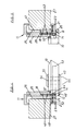
- FIGS. 6, 7 it is shown in FIGS. 6, 7 that a safety catch bolt 30 attached to a reinforcement bar 32 which is in turn on the end face 10 'of the casement spar 10 fixed with a fastening screw 59 is.
- the fishing area of the wing shown in Fig. 6,7 is provided with a fishing rebar plate 33, 34 on both sides.
- the fishing rod plate 34 protrudes over the Rollover 13 or up to the front side 10 'of the wing and protects accordingly.
- the opposite rebar 33 protrudes against the edge of the spar 10 or up to the end face 10 '. Both protect these edges accordingly.
- they are connected to one another by fastening screws 60 connected.
- the fastening screws 60 are arranged that they cannot be operated from the outside of the door. If the hinge side of the door leaf was the outside of the door, the screwing would have to be done the other way around, that is the heads of the screws 60 should be in the fishing rebar 33 be arranged.
- Fig. 14,15 show the fishing rebar plate 34 with others Details. It can be seen in particular that the fishing rebar plate 34 a bearing eye 34 'for a fishing pin 35 has, which protrudes on both sides of the bearing eye 34 '. Accordingly are two screw rods 25 attached, each 6 and / or 7 can be attached. Fig. 7 shows in contrast, that the fishing rebar plate 34 is not necessarily the storage of the wing must serve, but that a fishing pin 35 also in a conventional manner in the frame spar 10 of the wing can be screwed in with a bolt to serve the storage of a threaded rod 25.
- This Cover plate 36 ' is engaged by the hook 37 so that the Side cover strip 23 is fixed.
- Fig.9 is the side cover strip 23 provided with an impact piece 61 which for Jamming completely arranged in the side cover strip 23 is, however, has two fastening projections 39, which in Protrude towards the support bar 21.
- the support bar 21 has in turn corresponding press fit recesses 38 into which the fastening projections 39 can be driven, so that they are stuck in it and thus the side cover strips 23rd hold.
- the sectional view of the valid for Fig.9,10 9a shows the peg-like configuration of all fastening projections 39.
- the Frame spars 11 form together with not shown Crossbars a closed frame, just like that Wing frame spars 10 with a cross spars, not shown form closed casement.
- This casement is in accordance the hinge side shown in Fig.12 over at least two Swivel joints 62 connected to the frame, with a screw 24 the frame-side part of a swivel joint 62 and a roll tape sleeve 31 whose wing frame side part form.
- the roller band sleeve 31 is also designed, like the one trained in Fig. 1,3.
- Your safety catch bolt 30 engages in a not designated recess of a stiffening profile 14. Its edge 15 lies with the neighboring one Spar surface 16 flush.
- a mounting bar 18 attached, which in a corresponding, not shown in detail slot of the frame spar 11 engages.
- this mounting strip 18 is the stiffening profile 14 also attached on the hinge side according to Fig. 12, as shown in FIG. 11 by specifying a screwing point 63 was hinted at. It can also be seen from FIG. 12 that the threaded rod 24 is screwed into the mounting bar 18. 11 shows that a lock bolt 29 of the wing lock 53 engages in the stiffening profile 14.
Landscapes
- Engineering & Computer Science (AREA)
- Civil Engineering (AREA)
- Structural Engineering (AREA)
- Mechanical Engineering (AREA)
- Hinges (AREA)
- Securing Of Glass Panes Or The Like (AREA)
- Door And Window Frames Mounted To Openings (AREA)
- Wing Frames And Configurations (AREA)
- Chemical And Physical Treatments For Wood And The Like (AREA)
Description
- Fig. 1
- eine perspektivische Explosionszeichnung eines Teils eines vertikalen Blendrahmenholms einer Tür,
- Fig.2
- den Zusammenbau der Teile der Fig.1,
- Fig.3
- einen Teil des blendrahmenseitigen Türflügelrahmenbereichs in zwei, relativ zueinander gewendeten Darstellungen,
- Fig.4
- einen Horizontalschnitt im Verschlußbereich eines Blendrahmens einer Tür,
- Fig.5
- einen Horizontalschnitt anlenkungsseitig im Wandbereich eines Blendrahmens einer Tür,
- Fig.6,7
- der Fig.5 entsprechende Darstellungen mit detailmäßigen Abänderungen in vergrößerter Darstellung,
- Fig.8bis 10
- Detaildarstellungen zur Seitendeckleistenbefestigung des Blendrahmenholms eines Türflügels,
- Fig.8a, 9a
- zu den Fig.8 bis 10 gehörige Schnittdarstellungen im Befestigungsbereich,
- Fig.11,12
- Horizontalschnitte im Verschluß- und Wandbereich vertikaler hölzerner Fensterrahmen,
- Fig.13
- eine Aufsicht auf eine Verschlußbewehrungsplatte,
- Fig.14
- eine Aufsicht auf eine Angelbewehrungsplatte und
- Fig.15
- den Schnitt A-A der Fig.14.
Claims (12)
- Tür- oder Fensterflügelrahmen aus Holz, mit einem Flügelrahmenholm (10), der in einem einem Blendrahmenholm (11) benachbarten Angelbereich beidseitig mit je einer Angelbewehrungsplatte (33,34) versehen ist, die miteinander von der Flügelinnenseite her verschraubt sind, dadurch gekennzeichnet, daß von einer Stirnfläche (10') des Flügelrahmenholms (10) ein einen Spalt (64) zum Blendrahmenholm (11) abdeckender Rahmenüberschlag (13) vorspringt, der von der einen Angelbewehrungsplatte (34) bis an die Stirnfläche (10') des Flügelrahmenholms (10) heran abgedeckt ist, daß die zweite Angelbewehrungsplatte (33) bis an die Stirnfläche (10') des Flügelrahmenholms (10) heranreicht, und daß die Verschraubung der Angelbewehrungsplatten (33,34) flügelaußenseitig unbetätigbar ist.
- Rahmen nach Anspruch 1, dadurch gekennzeichnet, daß eine der Angelbewehrungsplatten (34) mit einem einstükkigen Lagerauge (34') für einen Angelbolzen (35) versehen ist.
- Rahmen nach Anspruch 1 oder 2, dadurch gekennzeichnet, daß mit einer Angelbewehrungsplatte (34) zwei Einschraubangeln (25) in Verbindung stehen, die an je einem Ende eines Angelbolzens (35) angreifen.
- Rahmen nach einem der Ansprüche 1 bis 3, der mit einem Blendrahmenkombiniert ist, dadurch gekennzeichnet, daß an der Stirnfläche (12) des Blendrahmenholms (11) ein metallenes Versteifungsprofil (14) über die gesamte Holmlänge angeordnet ist, das mit einer Kante (15) mit der dem Rahmenüberschlag (13) benachbarten Holmfläche (16) bündig liegt und alle erforderlichen Beschlagseingriffsaussparungen (17) aufweist.
- Rahmen nach Anspruch 4, dadurch gekennzeichnet, daß das metallene Versteifungsprofil (14) mit einer ebenen Einbauleiste (18) in einen Schlitz (19) des Blendrahmenholms (11) eingreift und dort befestigt ist.
- Rahmen nach Anspruch 5, dadurch gekennzeichnet, daß die Einbauleiste (18) im Winkel zum Versteifungsprofil (14) angeordnet ist und band- und/oder verschlußseitig in den Blendrahmenholm (11) eines Fensterrahmens eingreift.
- Rahmen nach Anspruch 5 oder 6, dadurch gekennzeichnet, daß eine Gewindeangel (24) für ein Fenster in die Einbauleiste (18) des Versteifungsprofils (14) eingeschraubt ist, oder daß eine Gewindeangel (25) für eine Tür in die Tragleiste (21) des Versteifungsprofils (14) eingeschraubt ist.
- Rahmen nach einem der Ansprüche 5 bis 7, dadurch gekennzeichnet, daß die Einbauleiste (18) mit einem als ebene Leiste ausgebildeten Versteifungsprofil (14) eine einstückige Bewehrungsleiste bildet und in ein Futterbrett (20) des band- und/oder verschlußseitigen Blendrahmenholms (11) eingreift.
- Rahmen nach einem der Ansprüche 4 bis 8, dadurch gekennzeichnet, daß eine Tragleiste (21) im Winkel am Versteifungsprofil (14) befestigt und band- und/ oder verschlußseitig mit der Rückseite (22) einer Seitendeckleiste (23) des Blendrahmenholms (11) verbunden ist.
- Rahmen nach einem der Ansprüche 4 bis 9, dadurch gekennzeichnet, daß eine Gewindeangel (25) für eine Tür in einen Sicherungswinkel (26) des Mauerwerks (27) und/oder in einen zwischen diesem und dem Futterbrett (20) angeordneten Verstärkungskloben (28) eingeschraubt ist.
- Rahmen nach einem der Ansprüche 4 bis 10, dadurch gekennzeichnet, daß Beschlagseingriffsaussparungen (17) für einen Schloßriegel (29), für eine Schloßfalle, für Beschlagsschließbolzen oder für Aushängesicherungsbolzen (30) vom Rahmenüberschlag (13) aus vor der Tragleiste (21) des Versteifungsprofils (14) angeordnet sind und/oder daß ein Aushängesicherungsbolzen (30) an einer Rollbandhülse (31) des Fenster- oder Türflügels angebracht ist, oder an einer dem Versteifungsprofil (14) parallelen Bewehrungsleiste (32) der Stirnfläche (10') des Fenster- oder Türflügels und/oder daß die Tragleiste (21) des Versteifungsprofils (14) mit Hinterschnittausnehmungen (36) für Einhängehaken (37) von Seitendeckleisten (23) oder mit Preßsitzausnehmungen (38) von Befestigungsvorsprüngen (39) der Seitendeckleisten (23) versehen ist.
- Rahmen nach einem der Ansprüche 1 bis 11, dadurch gekennzeichnet, daß ein Holm (10, 11) eines hölzernen Tür- oder Fensterflügels außen und/ oder innen im Verschlußbereich mit einer unabhängig von der Ausbildung des Flügelverschlusses bis nahezu an die Flügelstirnfläche (10') heranragenden Verschlußbewehrungsplatte (40) versehen ist.
Priority Applications (1)
| Application Number | Priority Date | Filing Date | Title |
|---|---|---|---|
| EP97105707A EP0786572A1 (de) | 1993-06-16 | 1994-05-26 | Tür- oder Fensterflügelrahmen aus Holz |
Applications Claiming Priority (2)
| Application Number | Priority Date | Filing Date | Title |
|---|---|---|---|
| DE4319945A DE4319945A1 (de) | 1993-06-16 | 1993-06-16 | Tür- oder Fensterrahmen aus Holz |
| DE4319945 | 1993-06-16 |
Related Child Applications (1)
| Application Number | Title | Priority Date | Filing Date |
|---|---|---|---|
| EP97105707A Division EP0786572A1 (de) | 1993-06-16 | 1994-05-26 | Tür- oder Fensterflügelrahmen aus Holz |
Publications (2)
| Publication Number | Publication Date |
|---|---|
| EP0629767A1 EP0629767A1 (de) | 1994-12-21 |
| EP0629767B1 true EP0629767B1 (de) | 1998-03-18 |
Family
ID=6490461
Family Applications (2)
| Application Number | Title | Priority Date | Filing Date |
|---|---|---|---|
| EP97105707A Withdrawn EP0786572A1 (de) | 1993-06-16 | 1994-05-26 | Tür- oder Fensterflügelrahmen aus Holz |
| EP94108075A Expired - Lifetime EP0629767B1 (de) | 1993-06-16 | 1994-05-26 | Tür- oder Fensterrahmen aus Holz |
Family Applications Before (1)
| Application Number | Title | Priority Date | Filing Date |
|---|---|---|---|
| EP97105707A Withdrawn EP0786572A1 (de) | 1993-06-16 | 1994-05-26 | Tür- oder Fensterflügelrahmen aus Holz |
Country Status (3)
| Country | Link |
|---|---|
| EP (2) | EP0786572A1 (de) |
| AT (1) | ATE164204T1 (de) |
| DE (2) | DE4319945A1 (de) |
Families Citing this family (4)
| Publication number | Priority date | Publication date | Assignee | Title |
|---|---|---|---|---|
| DE19500226C2 (de) * | 1995-01-05 | 1997-12-18 | Hans Dieter Niemann | Tür oder Fensterflügel |
| DE19814825A1 (de) * | 1998-04-02 | 1999-10-07 | Amang Aziz | Türrahmen |
| SE537296C2 (sv) * | 2010-06-22 | 2015-03-31 | Svenska Boprodukter Ab | Anordning för förankring av beslag vid fönster och dörrar |
| DE202010012276U1 (de) * | 2010-09-07 | 2010-11-18 | Holzbau Schmid Gmbh & Co. Kg | Türzarge, insbesondere für Brandschutzzwecke |
Family Cites Families (17)
| Publication number | Priority date | Publication date | Assignee | Title |
|---|---|---|---|---|
| DE7404683U (de) * | 1974-08-29 | Geromont W | Baufertigteil wie Tür, Fenster und dgl. mit einem in einem feststehenden Rahmen bewegbaren Flügel oder dgl | |
| US1814961A (en) * | 1930-01-23 | 1931-07-14 | Phillips James Edwin | Locking plate |
| FR1221872A (fr) * | 1959-01-17 | 1960-06-07 | Paumelle ou gond, non dégondable, pour meubles | |
| DE2153746A1 (de) * | 1971-10-28 | 1973-05-03 | Georg Dipl Kfm Ockenga | Befestigungsanordnung fuer tueren |
| US3888530A (en) * | 1972-05-12 | 1975-06-10 | Edward Fabrici | Bolt guards for door |
| DE2535651A1 (de) * | 1975-08-09 | 1977-02-10 | Gernot Ing Grad Andernach | Holztuerblatt mit holzzarge |
| FR2388108A1 (en) * | 1977-04-20 | 1978-11-17 | Renault Alain | Door hinge preventing forced entry - comprises two angle sections extending for entire door height and with welded hinge pins and sockets |
| US4139999A (en) * | 1978-02-03 | 1979-02-20 | M.A.G. Engineering Mfg. Co. | Protective door shield and locking mounting |
| DE3228413A1 (de) * | 1982-07-29 | 1984-02-02 | Angelos Athenai Theofilopoulos | System zur sicherung der tueren vor einbruechen |
| IE57539B1 (en) * | 1986-11-18 | 1992-11-18 | Kilhale Ltd | A reinforcing device for a door |
| GB8704137D0 (en) * | 1987-02-23 | 1987-04-01 | Mcdonald N K | Door reinforcing apparatus |
| US4763499A (en) * | 1987-04-07 | 1988-08-16 | Boyle John J | Door security system |
| DE3812965A1 (de) * | 1988-02-12 | 1989-08-24 | Helmut Lilge | Tuerband zum anlenken eines tuerblattes an einen tuerrahmen bei gebaeudetueren |
| GB2225808A (en) * | 1988-10-19 | 1990-06-13 | Batchit Limited | Connector for panels |
| DE8914908U1 (de) * | 1989-12-19 | 1990-02-01 | Herholz Bernhard Herbers GmbH & Co KG, 4422 Ahaus | Türrahmen aus Metallschiene und Verkleidung |
| DE9006633U1 (de) * | 1990-06-13 | 1990-08-16 | Kamuf, Gerhard, 6913 Mühlhausen | Tür mit Einbruchsicherung |
| FR2669076A1 (fr) * | 1990-11-13 | 1992-05-15 | Nevraumont Jean Pierre | Ensemble anti-effraction pour ouvrant, notamment pour porte. |
-
1993
- 1993-06-16 DE DE4319945A patent/DE4319945A1/de not_active Withdrawn
-
1994
- 1994-05-26 AT AT94108075T patent/ATE164204T1/de not_active IP Right Cessation
- 1994-05-26 EP EP97105707A patent/EP0786572A1/de not_active Withdrawn
- 1994-05-26 EP EP94108075A patent/EP0629767B1/de not_active Expired - Lifetime
- 1994-05-26 DE DE59405450T patent/DE59405450D1/de not_active Expired - Fee Related
Also Published As
| Publication number | Publication date |
|---|---|
| ATE164204T1 (de) | 1998-04-15 |
| DE4319945A1 (de) | 1994-12-22 |
| EP0629767A1 (de) | 1994-12-21 |
| DE59405450D1 (de) | 1998-04-23 |
| EP0786572A1 (de) | 1997-07-30 |
Similar Documents
| Publication | Publication Date | Title |
|---|---|---|
| EP1970523B1 (de) | Pfosten-Riegel-Fassade in einbruchhemmender Ausführung | |
| DE102009031035B4 (de) | Einbruchsicherung | |
| EP2113624B1 (de) | Tür- oder Fenstersicherungsvorrichtung | |
| EP0844348B1 (de) | Band für Türen oder Fenster | |
| DE9407569U1 (de) | Einbruchsicherung | |
| EP0786572A1 (de) | Tür- oder Fensterflügelrahmen aus Holz | |
| EP0761920B1 (de) | Fenster/Tür mit Dreh-Kipp-Beschlag | |
| EP0725202B1 (de) | Bewehrung an Türen oder Fenstern | |
| EP0733761B1 (de) | Flügelrahmen | |
| DE19509677A1 (de) | Sicherungsvorrichtung an Fenstern oder Türen | |
| DE19607557A1 (de) | Nachrüstzarge für Türen | |
| DE69901359T2 (de) | Zwischengeschaltete Sicherheitsvorrichtung für Drehtür oder Drehfenster | |
| EP0665354B1 (de) | Sicherheitseinrichtung für Türen, Fenster und dergleichen | |
| EP0995872B1 (de) | Tür- oder Fensterband | |
| DE3045813A1 (de) | Fenster oder tuer mit fluegel und rahmen | |
| DE102020001873A1 (de) | Modulare Tür- oder Fenstersicherung | |
| DE69705077T2 (de) | Scharnier | |
| EP0158069B1 (de) | Schliess- und Verriegelungsvorrichtung für eine Tür od. dgl. | |
| CH714946A2 (de) | Anordnung zum Schutz von Türen oder Fenstern gegen Einbruch. | |
| DE102011056206B4 (de) | Vertikal verriegelbare, zweiflügelige Sicherheitstüre sowie eine am Fußboden anbringbare Sperrplatte und eine Schutzwinkel-Leiste zur Verwendung mit einer solchen Sicherheitstüre | |
| DE10055777A1 (de) | Fenster oder Türe | |
| DE69910722T2 (de) | Doppelflügeleinheit ohne Mittelpfosten für Tür, Fenstertür oder dergleichen | |
| DE19704164C2 (de) | Vorrichtung zur Sicherung von Fenstern und Türen | |
| DE2553607A1 (de) | Holztuerstock mit einem schliessblech | |
| CH691914A5 (de) | Einbruchhemmendes Fenster. |
Legal Events
| Date | Code | Title | Description |
|---|---|---|---|
| PUAI | Public reference made under article 153(3) epc to a published international application that has entered the european phase |
Free format text: ORIGINAL CODE: 0009012 |
|
| AK | Designated contracting states |
Kind code of ref document: A1 Designated state(s): AT BE CH DE FR GB LI NL |
|
| 17P | Request for examination filed |
Effective date: 19950302 |
|
| 17Q | First examination report despatched |
Effective date: 19960923 |
|
| GRAG | Despatch of communication of intention to grant |
Free format text: ORIGINAL CODE: EPIDOS AGRA |
|
| GRAG | Despatch of communication of intention to grant |
Free format text: ORIGINAL CODE: EPIDOS AGRA |
|
| GRAH | Despatch of communication of intention to grant a patent |
Free format text: ORIGINAL CODE: EPIDOS IGRA |
|
| GRAH | Despatch of communication of intention to grant a patent |
Free format text: ORIGINAL CODE: EPIDOS IGRA |
|
| GRAA | (expected) grant |
Free format text: ORIGINAL CODE: 0009210 |
|
| AK | Designated contracting states |
Kind code of ref document: B1 Designated state(s): AT BE CH DE FR GB LI NL |
|
| DX | Miscellaneous (deleted) | ||
| REF | Corresponds to: |
Ref document number: 164204 Country of ref document: AT Date of ref document: 19980415 Kind code of ref document: T |
|
| REG | Reference to a national code |
Ref country code: CH Ref legal event code: NV Representative=s name: E. BLUM & CO. PATENTANWAELTE Ref country code: CH Ref legal event code: EP |
|
| REF | Corresponds to: |
Ref document number: 59405450 Country of ref document: DE Date of ref document: 19980423 |
|
| ET | Fr: translation filed | ||
| GBT | Gb: translation of ep patent filed (gb section 77(6)(a)/1977) |
Effective date: 19980501 |
|
| PLBE | No opposition filed within time limit |
Free format text: ORIGINAL CODE: 0009261 |
|
| STAA | Information on the status of an ep patent application or granted ep patent |
Free format text: STATUS: NO OPPOSITION FILED WITHIN TIME LIMIT |
|
| 26N | No opposition filed | ||
| PGFP | Annual fee paid to national office [announced via postgrant information from national office to epo] |
Ref country code: DE Payment date: 19990610 Year of fee payment: 6 |
|
| PGFP | Annual fee paid to national office [announced via postgrant information from national office to epo] |
Ref country code: GB Payment date: 19990614 Year of fee payment: 6 |
|
| PGFP | Annual fee paid to national office [announced via postgrant information from national office to epo] |
Ref country code: FR Payment date: 19990616 Year of fee payment: 6 |
|
| PGFP | Annual fee paid to national office [announced via postgrant information from national office to epo] |
Ref country code: CH Payment date: 19990617 Year of fee payment: 6 |
|
| PGFP | Annual fee paid to national office [announced via postgrant information from national office to epo] |
Ref country code: AT Payment date: 19990622 Year of fee payment: 6 |
|
| PGFP | Annual fee paid to national office [announced via postgrant information from national office to epo] |
Ref country code: NL Payment date: 19990624 Year of fee payment: 6 |
|
| PGFP | Annual fee paid to national office [announced via postgrant information from national office to epo] |
Ref country code: BE Payment date: 19990706 Year of fee payment: 6 |
|
| PG25 | Lapsed in a contracting state [announced via postgrant information from national office to epo] |
Ref country code: GB Free format text: LAPSE BECAUSE OF NON-PAYMENT OF DUE FEES Effective date: 20000526 Ref country code: AT Free format text: LAPSE BECAUSE OF NON-PAYMENT OF DUE FEES Effective date: 20000526 |
|
| PG25 | Lapsed in a contracting state [announced via postgrant information from national office to epo] |
Ref country code: LI Free format text: LAPSE BECAUSE OF NON-PAYMENT OF DUE FEES Effective date: 20000531 Ref country code: CH Free format text: LAPSE BECAUSE OF NON-PAYMENT OF DUE FEES Effective date: 20000531 Ref country code: BE Free format text: LAPSE BECAUSE OF NON-PAYMENT OF DUE FEES Effective date: 20000531 |
|
| BERE | Be: lapsed |
Owner name: NIEMANN HANS-DIETER Effective date: 20000531 |
|
| PG25 | Lapsed in a contracting state [announced via postgrant information from national office to epo] |
Ref country code: NL Free format text: LAPSE BECAUSE OF NON-PAYMENT OF DUE FEES Effective date: 20001201 |
|
| REG | Reference to a national code |
Ref country code: CH Ref legal event code: PL |
|
| GBPC | Gb: european patent ceased through non-payment of renewal fee |
Effective date: 20000526 |
|
| PG25 | Lapsed in a contracting state [announced via postgrant information from national office to epo] |
Ref country code: FR Free format text: LAPSE BECAUSE OF NON-PAYMENT OF DUE FEES Effective date: 20010131 |
|
| NLV4 | Nl: lapsed or anulled due to non-payment of the annual fee |
Effective date: 20001201 |
|
| PG25 | Lapsed in a contracting state [announced via postgrant information from national office to epo] |
Ref country code: DE Free format text: LAPSE BECAUSE OF NON-PAYMENT OF DUE FEES Effective date: 20010301 |
|
| REG | Reference to a national code |
Ref country code: FR Ref legal event code: ST |