EP0628236A1 - Dispositif réglable en hauteur - Google Patents
Dispositif réglable en hauteur Download PDFInfo
- Publication number
- EP0628236A1 EP0628236A1 EP94108211A EP94108211A EP0628236A1 EP 0628236 A1 EP0628236 A1 EP 0628236A1 EP 94108211 A EP94108211 A EP 94108211A EP 94108211 A EP94108211 A EP 94108211A EP 0628236 A1 EP0628236 A1 EP 0628236A1
- Authority
- EP
- European Patent Office
- Prior art keywords
- rocker
- lifting cylinder
- control valve
- frame
- adjusted
- Prior art date
- Legal status (The legal status is an assumption and is not a legal conclusion. Google has not performed a legal analysis and makes no representation as to the accuracy of the status listed.)
- Granted
Links
Images

Classifications
-
- A—HUMAN NECESSITIES
- A01—AGRICULTURE; FORESTRY; ANIMAL HUSBANDRY; HUNTING; TRAPPING; FISHING
- A01B—SOIL WORKING IN AGRICULTURE OR FORESTRY; PARTS, DETAILS, OR ACCESSORIES OF AGRICULTURAL MACHINES OR IMPLEMENTS, IN GENERAL
- A01B63/00—Lifting or adjusting devices or arrangements for agricultural machines or implements
- A01B63/14—Lifting or adjusting devices or arrangements for agricultural machines or implements for implements drawn by animals or tractors
- A01B63/16—Lifting or adjusting devices or arrangements for agricultural machines or implements for implements drawn by animals or tractors with wheels adjustable relatively to the frame
- A01B63/22—Lifting or adjusting devices or arrangements for agricultural machines or implements for implements drawn by animals or tractors with wheels adjustable relatively to the frame operated by hydraulic or pneumatic means
Definitions
- the invention relates to a height-adjustable device, in particular agricultural tillage device, with a frame and a lifting cylinder which can be controlled via a valve and by means of which the device can be adjusted between a transport position and an area of working positions of different depths.
- Such devices can be designed as disc harrows or as cultivators. They can generally be attached to a tractor, are supported on wheels and have a lifting shaft that can be rotated by at least one lifting cylinder. Via a transducer provided on the device, different signals are emitted depending on the respective height of the device.
- the tractor pulling the device is equipped with a hydraulic system and the control valve is connected between this system and the lifting cylinder.
- the soil tillage tools of the device work in different soil depths according to the respective requirements. At the end of a field, when the tractor and implement are turned, the implement is moved into its transport position and then lowered again. Finding the exact working depth presents considerable difficulties because the depth range in which the implement can work in the ground is relatively small compared to the adjustment range for transport.
- the invention provides that on the frame a directly or indirectly adjustable via the piston rod of the lifting cylinder Swing arm is connected, via which the closure element of the control valve can be actuated directly or indirectly.
- the rocker is adjusted, which can act directly on the control valve in such a way that a further movement of the piston in the lifting cylinder is interrupted.
- this solution should not exclude the possibility that the piston rod engages at a fixed point and the cylinder itself moves, which would then actuate the rocker in such a case. In any case, only a few movable parts are available for setting the position, which are also not exposed to major loads.
- an adjustable actuator is connected to the rocker which only needs to be adjusted for a further change in position.
- the range of motion of the rocker is adapted to the adjustment range of the closure element, which is why it is also proposed according to the invention that the rocker is articulated to a limited extent on the frame and has a contact element, against which one is provided on the piston rod of the lifting cylinder in the area of the working positions of the device Boom comes to the plant.
- the swing arm can be actuated directly from the lifting cylinder and not via a lifting shaft, the swing arm being adjusted only when the lifting cylinder approaches a position which corresponds to a working position of the device.
- the invention provides that the actuating member has a threaded section for receiving a clamping nut, which is connected to the rocker arm, and at one end with a contact surface for actuating the closure element of the control valve and in the area of the other End with a rotating device is provided.
- a rotating device which can be a crank
- the distance between the contact surface and the clamping nut changes, so that the control valve responds sooner or later depending on the direction of rotation.
- the rotating device can be easily placed at a location which is easily accessible for an operator.
- the rocker may be triangular or approximately triangular in shape and connected to the frame in a vertically pivotable manner, the pivot bearing point being provided in the region of the lower tip, the clamping nut being pivoted on the upper tip and the contact element as a against the action of a spring a cylinder part is formed on the front tip of the swing arm adjustable pin. If for some reason the rocker cannot be adjusted or can no longer be adjusted even though the piston rod adjusts the pin, the pin can yield due to its spring load and damage is avoided.
- a stop can be provided on the rocker at the rear of the pivot bearing point, which limits the rotational movement of the rocker away from the closure element of the control valve.
- the lifting cylinder can expediently be acted upon on one side and, when loaded, moves the device into its transport position, the control valve preventing a backflow of liquid from the lifting cylinder when the closing element is adjusted by the actuating element.
- the actuator in the region of its rotating device can also be provided with a depth indicator, by means of which the set working depth can be easily recognized.
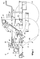
- Fig. 1 of the drawing part of an agricultural implement 10 can be seen with a main frame 12 which is supported on the ground by a vertically adjustable lifting wheel device 14, which in turn engages a lifting shaft 16.
- the lifting wheel device 14 essentially consists of two wheels 18 and 19 which are connected one behind the other with respect to the direction of travel and which are connected to a carrier 22.
- the carrier 22 in turn is pivotally connected to the lower end of a forward and downward extending arm 24, the upper end of which is fixedly connected to the lifting shaft 16, so that when the lifting shaft 16 is rotated about a transverse axis, the lifting arm 24 between a raised and in Fig. 1 with 24 R working position and a lowered and in Fig. 1 with 24 L transport position is adjustable.
- a hydraulic cylinder 26 has an end 27 on the cylinder side which is connected to a mast boom 30.
- the mast boom 30 is connected via screws 32 to a spar 12f of the main frame 12 which extends in the direction of travel and has a crossbeam 36 which, via the lifting wheel device 14, forms a similar connection to a second one, which is not shown in the drawing for the sake of simplicity and is also different Spar extending in the direction of travel extends on the other side of the lifting wheel device 14.
- a tab 37 provided with a through hole connects the cylinder-side end 27 of the hydraulic cylinder to the crossbar 36 in a pivotable manner.
- the piston-side end 40 of the hydraulic cylinder 26 is pivotable with a central portion of the lift arm 24 is connected via a pin 42 which has an extension 42e which extends transversely towards the spar 12f.
- a depth control system 50 is connected to the frame 12 in the region of the hydraulic cylinder 26.
- the depth control system 50 is shaped by a movable or rotatable rocker 52. From Fig. 2 it can now be seen that the rocker 52 is pivotally connected to the main frame 12 in the region of the cylinder 26 and responds to an extension of the cylinder.
- a control valve 54 is provided, which is connected via hydraulic lines 55 and 56 to the hydraulic cylinder 26 and to a pressure fluid source on the pulling vehicle, not shown, for controlling the cylinder 26.
- the valve 54 has a slide control 58 or the like serving as a closure element.
- An adjustable actuator 60 is carried by the rocker 52 and is movable together with the rocker in a way that inhibits the slide control 58.
- the length of the actuator 60 between the rocker 52 and the slide control 58 (see 60 L in Fig. 2) is adjustable from a location farther from the rocker 52 to obtain an adjustable frame working height that is immediate from the piston rod position , as will be explained in more detail below, is dependent.
- the rocker 52 is approximately triangular is formed and has a pivot bearing 72 in the area of the lowermost tip for connection to the one spar of the main frame 12.
- a contact element 74 which can be actuated via the extension 42e of the pin 42 is arranged on the forward-facing side of the rocker.
- a cylinder part 75 is therefore firmly connected to this side, in which the shaft of a screw 74b, the length of which is considerably greater than that of the cylinder part 75, can be displaced.
- the shaft of the screw 74b is pressed down by a spring 74s in such a way that, when the rocker 52 is articulated on the main frame 12, the screw head 74h lies in the range of motion of the extension 42e.
- the upper tip of the rocker 52 is determined by a bracket strap 76, which can be screwed to the rocker 52.
- the rocker arm 52 can be articulated to one of the spars of the main frame 12, which is why a shaft 78 is connected to it so that the rocker arm 52 can be adjusted about a transverse axis which runs parallel to that of the lifting shaft 16.
- the pivot bearing 72 of the rocker is also provided with a nose-like stop 80 which can come to rest against a screw holder 82 which is also arranged on the main frame 12.
- the screw holder 82 is provided at the rear and below the shaft 78, so that a forward and downward rotational movement of the rocker 52 is limited in the clockwise direction.
- the stop 80 is preferably arranged such that the extension 42e does not move against the screw head 74h until the piston has been inserted into the cylinder 26 to such an extent that the main frame 12 approaches its area for depth control.
- the spring 74s is compressible, so that the shaft of the screw 74s can move in the cylinder part 75 if, for some reason, the rocker 52 can no longer be moved counterclockwise. In this way, possible damage to the components is avoided.
- a valve holder 84 which extends backwards and upwards, is connected to the spar 12f of the main frame 12 via the screw holder 82 and a second screw 83.
- the control valve 54 is connected to the valve holder 84 at the rear of the pivot axis of the shaft 72 at a height which corresponds approximately to the highest position of the bracket plate 76, as can be seen from FIG. 1.
- a tension nut 90 or a sleeve is pivotally connected to the bracket tab 76 and is internally threaded to accommodate the threaded end of the actuator 60.
- the front end of the actuating member 60 shown in FIG. 1 is designed as a rotating device in the form of a crank 92.
- Crank 92 is provided in an easily accessible location and when actuated, actuator 60 rotates about its longitudinal axis, whereby the depth control setting can be changed.
- the front end of the actuator 60 is still received by a tab 94, the lower end of which is screwed to the spar 12f of the main frame 12.
- a depth indicator 94 is also provided on the tab 94, which cooperates with a ring 98 fixedly arranged on the actuating member 60 in order to be able to display the selected depth setting.
- the remote from the crank 92 and threaded end of the actuator 60 is screwed into the clamping nut 90 and exits from the other end and is also equipped on its end face with a contact surface 102, via which the slide control of the control valve 54 can be actuated. Between the contact surface 102 and the clamping nut 90 there is still a spacer 104 on the actuating member 60, which limits the path which the actuating member can be adjusted forwards with respect to the clamping nut 90.
- the working depth of the implement can be adjusted by turning the crank 92.
- the slide control 58 of the control valve is already actuated at a smaller angle of rotation of the rocker 52, as a result of which a smaller working depth is set, which results in a greater distance between the main frame 12 and the floor surface.
- a reduction in the distance 60 L causes the sliding control 58 to be adjusted only after a larger angle of rotation of the rocker 52 and thus a greater working depth.
- the crank of the actuator can still be rotated to change the distance 60 L and thus the working depth.
Landscapes
- Life Sciences & Earth Sciences (AREA)
- Zoology (AREA)
- Engineering & Computer Science (AREA)
- Mechanical Engineering (AREA)
- Soil Sciences (AREA)
- Environmental Sciences (AREA)
- Lifting Devices For Agricultural Implements (AREA)
- Soil Working Implements (AREA)
Applications Claiming Priority (2)
| Application Number | Priority Date | Filing Date | Title |
|---|---|---|---|
| US08/074,233 US5366024A (en) | 1993-06-09 | 1993-06-09 | Remotely adjustable depth control |
| US74233 | 1993-06-09 |
Publications (2)
| Publication Number | Publication Date |
|---|---|
| EP0628236A1 true EP0628236A1 (fr) | 1994-12-14 |
| EP0628236B1 EP0628236B1 (fr) | 1996-11-27 |
Family
ID=22118472
Family Applications (1)
| Application Number | Title | Priority Date | Filing Date |
|---|---|---|---|
| EP94108211A Expired - Lifetime EP0628236B1 (fr) | 1993-06-09 | 1994-05-28 | Dispositif réglable en hauteur |
Country Status (5)
| Country | Link |
|---|---|
| US (1) | US5366024A (fr) |
| EP (1) | EP0628236B1 (fr) |
| AU (1) | AU671904B2 (fr) |
| CA (1) | CA2112344C (fr) |
| DE (1) | DE59401115D1 (fr) |
Families Citing this family (16)
| Publication number | Priority date | Publication date | Assignee | Title |
|---|---|---|---|---|
| US5988293A (en) * | 1998-05-12 | 1999-11-23 | Deere & Company | Gauge structure for a cylinder operated depth control |
| US5911279A (en) * | 1998-09-29 | 1999-06-15 | Whitener; Harold L. | Automated ripper depth adjustor apparatus |
| US6786130B2 (en) * | 2002-10-25 | 2004-09-07 | Deere & Company | Directly actuated depth control |
| US7204319B2 (en) * | 2004-09-30 | 2007-04-17 | Deere & Company | Jointed rockshaft with angularly adjustable segments |
| WO2008153757A1 (fr) | 2007-05-23 | 2008-12-18 | Tim Criswell | Machine d'encaissage automatique et son procédé d'utilisation |
| US9148988B2 (en) * | 2009-08-06 | 2015-10-06 | Penta TMR Inc. | Depth control system |
| CA2712334C (fr) * | 2009-08-06 | 2017-05-30 | Penta TMR Inc. | Systeme de commande de la profondeur |
| US8857530B2 (en) | 2011-03-07 | 2014-10-14 | Cnh Industrial Canada, Ltd. | Automatic depth control system for an agricultural implement |
| EP2713690B1 (fr) | 2011-06-03 | 2017-08-09 | Precision Planting LLC | Appareil, systèmes et procédés pour barre porte-outils agricole |
| WO2013155194A1 (fr) | 2012-04-10 | 2013-10-17 | Absolute Innovations, Inc. | Machines de travail du sol autopropulsées |
| US10149440B2 (en) | 2015-01-22 | 2018-12-11 | Abi Attachments, Inc. | Edging tools for work machines |
| EP3827658A1 (fr) | 2016-02-19 | 2021-06-02 | Precision Planting LLC | Unité de rangée agricole avec assemblage de réglage de la profondeur |
| US10501912B2 (en) | 2017-02-16 | 2019-12-10 | Abi Attachments, Inc. | Grading tool compatible with light duty work machine |
| AU2019228086B2 (en) | 2018-03-01 | 2024-03-28 | Precision Planting Llc | Agricultural trench depth systems, and apparatus |
| US11019762B2 (en) | 2018-07-12 | 2021-06-01 | Cnh Industrial Canada, Ltd. | Precision depth control of seed planting units of an agricultural implement |
| US11624161B1 (en) | 2019-11-19 | 2023-04-11 | Abi Attachments, Inc. | Roller attachments for work machines and operation thereof |
Citations (4)
| Publication number | Priority date | Publication date | Assignee | Title |
|---|---|---|---|---|
| US2606532A (en) * | 1952-02-19 | 1952-08-12 | Joseph F Ziskal | Stop mechanism for implement adjusting cylinders |
| FR2434551A1 (fr) * | 1978-08-30 | 1980-03-28 | Craven Tasker Andover Ltd | Perfectionnements apportes a des instruments aratoires |
| DE3139936A1 (de) * | 1981-10-08 | 1983-04-28 | Maschinenfabriken Bernard Krone Gmbh, 4441 Spelle | Landwirtschaftliches anhaengegeraet |
| GB2145611A (en) * | 1983-09-01 | 1985-04-03 | Lely Nv C Van Der | Soil cultivating implements |
Family Cites Families (5)
| Publication number | Priority date | Publication date | Assignee | Title |
|---|---|---|---|---|
| US3057092A (en) * | 1961-01-09 | 1962-10-09 | Gurries Mfg Co | Valve operating unit for a leveling system |
| US3700643A (en) * | 1970-09-02 | 1972-10-24 | Union Carbide Corp | Radiation-curable acrylate-capped polycaprolactone compositions |
| US4360067A (en) * | 1981-04-10 | 1982-11-23 | Chromalloy American Corporation | Transport lock system for an implement or the like |
| US4782201A (en) * | 1987-06-29 | 1988-11-01 | J. I. Case Company | Switch actuating assembly |
| US5277257A (en) * | 1992-10-05 | 1994-01-11 | Deere & Company | Depth control mechanism for an implement |
-
1993
- 1993-06-09 US US08/074,233 patent/US5366024A/en not_active Expired - Lifetime
- 1993-12-23 CA CA002112344A patent/CA2112344C/fr not_active Expired - Lifetime
-
1994
- 1994-04-29 AU AU60788/94A patent/AU671904B2/en not_active Expired
- 1994-05-28 DE DE59401115T patent/DE59401115D1/de not_active Expired - Lifetime
- 1994-05-28 EP EP94108211A patent/EP0628236B1/fr not_active Expired - Lifetime
Patent Citations (4)
| Publication number | Priority date | Publication date | Assignee | Title |
|---|---|---|---|---|
| US2606532A (en) * | 1952-02-19 | 1952-08-12 | Joseph F Ziskal | Stop mechanism for implement adjusting cylinders |
| FR2434551A1 (fr) * | 1978-08-30 | 1980-03-28 | Craven Tasker Andover Ltd | Perfectionnements apportes a des instruments aratoires |
| DE3139936A1 (de) * | 1981-10-08 | 1983-04-28 | Maschinenfabriken Bernard Krone Gmbh, 4441 Spelle | Landwirtschaftliches anhaengegeraet |
| GB2145611A (en) * | 1983-09-01 | 1985-04-03 | Lely Nv C Van Der | Soil cultivating implements |
Also Published As
| Publication number | Publication date |
|---|---|
| DE59401115D1 (de) | 1997-01-09 |
| AU671904B2 (en) | 1996-09-12 |
| AU6078894A (en) | 1994-12-15 |
| CA2112344C (fr) | 1995-09-26 |
| US5366024A (en) | 1994-11-22 |
| EP0628236B1 (fr) | 1996-11-27 |
| CA2112344A1 (fr) | 1994-12-10 |
Similar Documents
| Publication | Publication Date | Title |
|---|---|---|
| EP0605851B1 (fr) | Réglage de position d'un outil remorqué par un tracteur | |
| EP0628236B1 (fr) | Dispositif réglable en hauteur | |
| EP1417876A1 (fr) | Système de réglage | |
| EP0094072B1 (fr) | Machine pour le travail du sol | |
| WO2014067508A1 (fr) | Charrue demi-tour avec limitation de rotation | |
| DE1557775A1 (de) | Regelmittel fuer Zugwiderstand und Arbeitstiefe | |
| DE2555890B2 (de) | Ueberlastsicherung der verbindung zwischen den pflugkoerpern und dem pflugrahmen eines ein- oder mehrscharigen volldrehpfluges | |
| EP0556459B1 (fr) | Charrue réversible attelable ou accrochable | |
| AT392193B (de) | Verfahrbare vorrichtung zur bodenbearbeitung von grundstuecken | |
| DE2504071C3 (de) | Aufsatteldrehpflug | |
| DE3232743A1 (de) | Vorrichtung zum verbessern der bodenhaftung eines schleppers, der bodenbearbeitungswerkzeuge traegt | |
| DE3513096A1 (de) | Anbaupflug | |
| EP0216997B1 (fr) | Charrue réversible | |
| DE102004025478B4 (de) | Landwirtschaftliche Maschine | |
| DE2655236A1 (de) | Zugkraft- und lageregelvorrichtung fuer zugmaschinen mit anbaugeraeten | |
| DE931323C (de) | Radspurlockerer | |
| DE870612C (de) | Einstellvorrichtung fuer von einem Schlepper gezogene landwirtschaftliche Anhaengegeraete | |
| DE19623391A1 (de) | Landwirtschaftliches Fahrzeug mit angebautem Huborgan | |
| DE2249536A1 (de) | Zugmaschine mit einer zuggestaengesteuervorrichtung | |
| DE2622481B2 (de) | Vorrichtung zum Einbringen von flüssigem Düngemittel, insbesondere Gülle, in Kulturböden | |
| DE948092C (de) | Anbauscheibenschwenkpflung, dessen Pflugscheiben beim Heben des Pfluges von einer Arbeitsstellung in die andere geschwenkt werden | |
| EP0213579A2 (fr) | Machine agricole comportant un châssis et un cadre support d'outils | |
| DE3618064A1 (de) | Pflug | |
| DE1482073C (de) | Mähwerk zum rückwärtigen Anbau an Ackerschlepper | |
| DE1782664C3 (de) | Pflug, insbesondere Anhänge- oder Aufsattelpflug |
Legal Events
| Date | Code | Title | Description |
|---|---|---|---|
| PUAI | Public reference made under article 153(3) epc to a published international application that has entered the european phase |
Free format text: ORIGINAL CODE: 0009012 |
|
| AK | Designated contracting states |
Kind code of ref document: A1 Designated state(s): DE FR GB IT |
|
| 17P | Request for examination filed |
Effective date: 19941026 |
|
| GRAG | Despatch of communication of intention to grant |
Free format text: ORIGINAL CODE: EPIDOS AGRA |
|
| GRAH | Despatch of communication of intention to grant a patent |
Free format text: ORIGINAL CODE: EPIDOS IGRA |
|
| 17Q | First examination report despatched |
Effective date: 19960510 |
|
| GRAH | Despatch of communication of intention to grant a patent |
Free format text: ORIGINAL CODE: EPIDOS IGRA |
|
| GRAA | (expected) grant |
Free format text: ORIGINAL CODE: 0009210 |
|
| AK | Designated contracting states |
Kind code of ref document: B1 Designated state(s): DE FR GB IT |
|
| GBT | Gb: translation of ep patent filed (gb section 77(6)(a)/1977) |
Effective date: 19961127 |
|
| REF | Corresponds to: |
Ref document number: 59401115 Country of ref document: DE Date of ref document: 19970109 |
|
| ET | Fr: translation filed | ||
| ITF | It: translation for a ep patent filed |
Owner name: LENZI & C. |
|
| PLBE | No opposition filed within time limit |
Free format text: ORIGINAL CODE: 0009261 |
|
| STAA | Information on the status of an ep patent application or granted ep patent |
Free format text: STATUS: NO OPPOSITION FILED WITHIN TIME LIMIT |
|
| 26N | No opposition filed | ||
| REG | Reference to a national code |
Ref country code: GB Ref legal event code: IF02 |
|
| PGFP | Annual fee paid to national office [announced via postgrant information from national office to epo] |
Ref country code: GB Payment date: 20130528 Year of fee payment: 20 Ref country code: DE Payment date: 20130419 Year of fee payment: 20 |
|
| PGFP | Annual fee paid to national office [announced via postgrant information from national office to epo] |
Ref country code: FR Payment date: 20130606 Year of fee payment: 20 Ref country code: IT Payment date: 20130524 Year of fee payment: 20 |
|
| REG | Reference to a national code |
Ref country code: DE Ref legal event code: R071 Ref document number: 59401115 Country of ref document: DE |
|
| REG | Reference to a national code |
Ref country code: GB Ref legal event code: PE20 Expiry date: 20140527 |
|
| PG25 | Lapsed in a contracting state [announced via postgrant information from national office to epo] |
Ref country code: GB Free format text: LAPSE BECAUSE OF EXPIRATION OF PROTECTION Effective date: 20140527 |
|
| PG25 | Lapsed in a contracting state [announced via postgrant information from national office to epo] |
Ref country code: DE Free format text: LAPSE BECAUSE OF EXPIRATION OF PROTECTION Effective date: 20140529 |