EP0628236A1 - Height-adjustable device - Google Patents
Height-adjustable device Download PDFInfo
- Publication number
- EP0628236A1 EP0628236A1 EP94108211A EP94108211A EP0628236A1 EP 0628236 A1 EP0628236 A1 EP 0628236A1 EP 94108211 A EP94108211 A EP 94108211A EP 94108211 A EP94108211 A EP 94108211A EP 0628236 A1 EP0628236 A1 EP 0628236A1
- Authority
- EP
- European Patent Office
- Prior art keywords
- rocker
- lifting cylinder
- control valve
- frame
- adjusted
- Prior art date
- Legal status (The legal status is an assumption and is not a legal conclusion. Google has not performed a legal analysis and makes no representation as to the accuracy of the status listed.)
- Granted
Links
Images

Classifications
-
- A—HUMAN NECESSITIES
- A01—AGRICULTURE; FORESTRY; ANIMAL HUSBANDRY; HUNTING; TRAPPING; FISHING
- A01B—SOIL WORKING IN AGRICULTURE OR FORESTRY; PARTS, DETAILS, OR ACCESSORIES OF AGRICULTURAL MACHINES OR IMPLEMENTS, IN GENERAL
- A01B63/00—Lifting or adjusting devices or arrangements for agricultural machines or implements
- A01B63/14—Lifting or adjusting devices or arrangements for agricultural machines or implements for implements drawn by animals or tractors
- A01B63/16—Lifting or adjusting devices or arrangements for agricultural machines or implements for implements drawn by animals or tractors with wheels adjustable relatively to the frame
- A01B63/22—Lifting or adjusting devices or arrangements for agricultural machines or implements for implements drawn by animals or tractors with wheels adjustable relatively to the frame operated by hydraulic or pneumatic means
Definitions
- the invention relates to a height-adjustable device, in particular agricultural tillage device, with a frame and a lifting cylinder which can be controlled via a valve and by means of which the device can be adjusted between a transport position and an area of working positions of different depths.
- Such devices can be designed as disc harrows or as cultivators. They can generally be attached to a tractor, are supported on wheels and have a lifting shaft that can be rotated by at least one lifting cylinder. Via a transducer provided on the device, different signals are emitted depending on the respective height of the device.
- the tractor pulling the device is equipped with a hydraulic system and the control valve is connected between this system and the lifting cylinder.
- the soil tillage tools of the device work in different soil depths according to the respective requirements. At the end of a field, when the tractor and implement are turned, the implement is moved into its transport position and then lowered again. Finding the exact working depth presents considerable difficulties because the depth range in which the implement can work in the ground is relatively small compared to the adjustment range for transport.
- the invention provides that on the frame a directly or indirectly adjustable via the piston rod of the lifting cylinder Swing arm is connected, via which the closure element of the control valve can be actuated directly or indirectly.
- the rocker is adjusted, which can act directly on the control valve in such a way that a further movement of the piston in the lifting cylinder is interrupted.
- this solution should not exclude the possibility that the piston rod engages at a fixed point and the cylinder itself moves, which would then actuate the rocker in such a case. In any case, only a few movable parts are available for setting the position, which are also not exposed to major loads.
- an adjustable actuator is connected to the rocker which only needs to be adjusted for a further change in position.
- the range of motion of the rocker is adapted to the adjustment range of the closure element, which is why it is also proposed according to the invention that the rocker is articulated to a limited extent on the frame and has a contact element, against which one is provided on the piston rod of the lifting cylinder in the area of the working positions of the device Boom comes to the plant.
- the swing arm can be actuated directly from the lifting cylinder and not via a lifting shaft, the swing arm being adjusted only when the lifting cylinder approaches a position which corresponds to a working position of the device.
- the invention provides that the actuating member has a threaded section for receiving a clamping nut, which is connected to the rocker arm, and at one end with a contact surface for actuating the closure element of the control valve and in the area of the other End with a rotating device is provided.
- a rotating device which can be a crank
- the distance between the contact surface and the clamping nut changes, so that the control valve responds sooner or later depending on the direction of rotation.
- the rotating device can be easily placed at a location which is easily accessible for an operator.
- the rocker may be triangular or approximately triangular in shape and connected to the frame in a vertically pivotable manner, the pivot bearing point being provided in the region of the lower tip, the clamping nut being pivoted on the upper tip and the contact element as a against the action of a spring a cylinder part is formed on the front tip of the swing arm adjustable pin. If for some reason the rocker cannot be adjusted or can no longer be adjusted even though the piston rod adjusts the pin, the pin can yield due to its spring load and damage is avoided.
- a stop can be provided on the rocker at the rear of the pivot bearing point, which limits the rotational movement of the rocker away from the closure element of the control valve.
- the lifting cylinder can expediently be acted upon on one side and, when loaded, moves the device into its transport position, the control valve preventing a backflow of liquid from the lifting cylinder when the closing element is adjusted by the actuating element.
- the actuator in the region of its rotating device can also be provided with a depth indicator, by means of which the set working depth can be easily recognized.
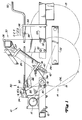
- Fig. 1 of the drawing part of an agricultural implement 10 can be seen with a main frame 12 which is supported on the ground by a vertically adjustable lifting wheel device 14, which in turn engages a lifting shaft 16.
- the lifting wheel device 14 essentially consists of two wheels 18 and 19 which are connected one behind the other with respect to the direction of travel and which are connected to a carrier 22.
- the carrier 22 in turn is pivotally connected to the lower end of a forward and downward extending arm 24, the upper end of which is fixedly connected to the lifting shaft 16, so that when the lifting shaft 16 is rotated about a transverse axis, the lifting arm 24 between a raised and in Fig. 1 with 24 R working position and a lowered and in Fig. 1 with 24 L transport position is adjustable.
- a hydraulic cylinder 26 has an end 27 on the cylinder side which is connected to a mast boom 30.
- the mast boom 30 is connected via screws 32 to a spar 12f of the main frame 12 which extends in the direction of travel and has a crossbeam 36 which, via the lifting wheel device 14, forms a similar connection to a second one, which is not shown in the drawing for the sake of simplicity and is also different Spar extending in the direction of travel extends on the other side of the lifting wheel device 14.
- a tab 37 provided with a through hole connects the cylinder-side end 27 of the hydraulic cylinder to the crossbar 36 in a pivotable manner.
- the piston-side end 40 of the hydraulic cylinder 26 is pivotable with a central portion of the lift arm 24 is connected via a pin 42 which has an extension 42e which extends transversely towards the spar 12f.
- a depth control system 50 is connected to the frame 12 in the region of the hydraulic cylinder 26.
- the depth control system 50 is shaped by a movable or rotatable rocker 52. From Fig. 2 it can now be seen that the rocker 52 is pivotally connected to the main frame 12 in the region of the cylinder 26 and responds to an extension of the cylinder.
- a control valve 54 is provided, which is connected via hydraulic lines 55 and 56 to the hydraulic cylinder 26 and to a pressure fluid source on the pulling vehicle, not shown, for controlling the cylinder 26.
- the valve 54 has a slide control 58 or the like serving as a closure element.
- An adjustable actuator 60 is carried by the rocker 52 and is movable together with the rocker in a way that inhibits the slide control 58.
- the length of the actuator 60 between the rocker 52 and the slide control 58 (see 60 L in Fig. 2) is adjustable from a location farther from the rocker 52 to obtain an adjustable frame working height that is immediate from the piston rod position , as will be explained in more detail below, is dependent.
- the rocker 52 is approximately triangular is formed and has a pivot bearing 72 in the area of the lowermost tip for connection to the one spar of the main frame 12.
- a contact element 74 which can be actuated via the extension 42e of the pin 42 is arranged on the forward-facing side of the rocker.
- a cylinder part 75 is therefore firmly connected to this side, in which the shaft of a screw 74b, the length of which is considerably greater than that of the cylinder part 75, can be displaced.
- the shaft of the screw 74b is pressed down by a spring 74s in such a way that, when the rocker 52 is articulated on the main frame 12, the screw head 74h lies in the range of motion of the extension 42e.
- the upper tip of the rocker 52 is determined by a bracket strap 76, which can be screwed to the rocker 52.
- the rocker arm 52 can be articulated to one of the spars of the main frame 12, which is why a shaft 78 is connected to it so that the rocker arm 52 can be adjusted about a transverse axis which runs parallel to that of the lifting shaft 16.
- the pivot bearing 72 of the rocker is also provided with a nose-like stop 80 which can come to rest against a screw holder 82 which is also arranged on the main frame 12.
- the screw holder 82 is provided at the rear and below the shaft 78, so that a forward and downward rotational movement of the rocker 52 is limited in the clockwise direction.
- the stop 80 is preferably arranged such that the extension 42e does not move against the screw head 74h until the piston has been inserted into the cylinder 26 to such an extent that the main frame 12 approaches its area for depth control.
- the spring 74s is compressible, so that the shaft of the screw 74s can move in the cylinder part 75 if, for some reason, the rocker 52 can no longer be moved counterclockwise. In this way, possible damage to the components is avoided.
- a valve holder 84 which extends backwards and upwards, is connected to the spar 12f of the main frame 12 via the screw holder 82 and a second screw 83.
- the control valve 54 is connected to the valve holder 84 at the rear of the pivot axis of the shaft 72 at a height which corresponds approximately to the highest position of the bracket plate 76, as can be seen from FIG. 1.
- a tension nut 90 or a sleeve is pivotally connected to the bracket tab 76 and is internally threaded to accommodate the threaded end of the actuator 60.
- the front end of the actuating member 60 shown in FIG. 1 is designed as a rotating device in the form of a crank 92.
- Crank 92 is provided in an easily accessible location and when actuated, actuator 60 rotates about its longitudinal axis, whereby the depth control setting can be changed.
- the front end of the actuator 60 is still received by a tab 94, the lower end of which is screwed to the spar 12f of the main frame 12.
- a depth indicator 94 is also provided on the tab 94, which cooperates with a ring 98 fixedly arranged on the actuating member 60 in order to be able to display the selected depth setting.
- the remote from the crank 92 and threaded end of the actuator 60 is screwed into the clamping nut 90 and exits from the other end and is also equipped on its end face with a contact surface 102, via which the slide control of the control valve 54 can be actuated. Between the contact surface 102 and the clamping nut 90 there is still a spacer 104 on the actuating member 60, which limits the path which the actuating member can be adjusted forwards with respect to the clamping nut 90.
- the working depth of the implement can be adjusted by turning the crank 92.
- the slide control 58 of the control valve is already actuated at a smaller angle of rotation of the rocker 52, as a result of which a smaller working depth is set, which results in a greater distance between the main frame 12 and the floor surface.
- a reduction in the distance 60 L causes the sliding control 58 to be adjusted only after a larger angle of rotation of the rocker 52 and thus a greater working depth.
- the crank of the actuator can still be rotated to change the distance 60 L and thus the working depth.
Abstract
Bei einem höhenverstellbaren Gerät, insbesondere landwirtschaftlichen Bodenbearbeitungsgerät, mit einem Rahmen (12) und einem über ein Ventil (54) steuerbaren Hubzylinder (26), über den das Gerät (10) zwischen einer Transportstellung und einem Bereich unterschiedlich tiefer Arbeitsstellungen verstellbar ist, ist an dem Rahmen (12) eine über die Kolbenstange des Hubzylinders (26) mittel- oder unmittelbar verstellbare Schwinge (52) angeschlossen, über die das Verschlußelement des Steuerventils (54) mittel- oder unmittelbar betätigbar ist, wodurch ein Flüssigkeitsrückfluß aus dem Hubzylinder (26) unterbrochen und das Gerät in der damit festgelegten Höhenstellung gehalten wird. <IMAGE>In the case of a height-adjustable device, in particular agricultural tillage device, with a frame (12) and a lifting cylinder (26) which can be controlled via a valve (54) and via which the device (10) can be adjusted between a transport position and an area of working positions of different depths connected to the frame (12) via the piston rod of the lifting cylinder (26) directly or indirectly rocker arm (52), via which the closure element of the control valve (54) can be actuated directly or indirectly, thereby causing a backflow of liquid from the lifting cylinder (26) interrupted and the device is held in the height position thus defined. <IMAGE>
Description
Die Erfindung bezieht sich auf ein höhenverstellbares Gerät, insbesondere landwirtschaftliches Bodenbearbeitungsgerät, mit einem Rahmen und einem über ein Ventil steuerbaren Hubzylinder, über den das Gerät zwischen einer Transportstellung und einem Bereich unterschiedlich tiefer Arbeitsstellungen verstellbar ist.The invention relates to a height-adjustable device, in particular agricultural tillage device, with a frame and a lifting cylinder which can be controlled via a valve and by means of which the device can be adjusted between a transport position and an area of working positions of different depths.
Derartige Geräte (US-A-5 152 347) können als Scheibeneggen oder als Kultivatoren ausgebildet sein. Sie sind in der Regel an einen Schlepper anhängbar, stützen sich auf Laufrädern ab und weisen eine Hubwelle auf, die durch mindestens einen Hubzylinder drehbar ist. Über einen am Gerät vorgesehenen Wandler werden in Abhängigkeit von der jeweiligen Höhe des Gerätes unterschiedliche Signale abgegeben. Der das Gerät ziehende Schlepper ist mit einem hydraulischen System ausgestattet und das Steuerventil ist zwischen dieses System und den Hubzylinder geschaltet. Die Bodenbearbeitungswerkzeuge des Gerätes arbeiten entsprechend der jeweiligen Anforderungen in unterschiedlichen Bodentiefen. Am Ende eines Feldes, wenn Schlepper und Gerät gewendet werden, wird das Gerät in seine Transportstellung verstellt und danach wieder abgesenkt. Das Wiederauffinden der genauen Arbeitstiefe bereitet dabei nicht unerhebliche Schwierigkeiten, weil der Tiefenbereich, in dem das Arbeitsgerät im Boden arbeiten kann, im Vergleich zu dem Verstellbereich für den Transport relativ klein ist.Such devices (US-A-5 152 347) can be designed as disc harrows or as cultivators. They can generally be attached to a tractor, are supported on wheels and have a lifting shaft that can be rotated by at least one lifting cylinder. Via a transducer provided on the device, different signals are emitted depending on the respective height of the device. The tractor pulling the device is equipped with a hydraulic system and the control valve is connected between this system and the lifting cylinder. The soil tillage tools of the device work in different soil depths according to the respective requirements. At the end of a field, when the tractor and implement are turned, the implement is moved into its transport position and then lowered again. Finding the exact working depth presents considerable difficulties because the depth range in which the implement can work in the ground is relatively small compared to the adjustment range for transport.
Andererseits ist es auch nicht mehr neu, an der Hubwelle ein Gestänge angreifen zu lassen, das das Steuerventil betätigt, um eine vorgewählte Arbeitstiefe wieder auffinden zu können. Hierdurch werden aber die vorgenannten Nachteile auch nicht ausgeschlossen, weil die Lagerstellen der Hubwellen relativ schnell ausschlagen.On the other hand, it is no longer new to have a linkage on the lifting shaft that actuates the control valve in order to be able to find a preselected working depth again. This does not rule out the aforementioned disadvantages, however, because the bearing points of the lifting shafts deflect relatively quickly.
Die mit der Erfindung zu lösende Aufgabe wird in einer einfachen und möglichst störunanfälligen Einrichtung zur Einstellung der jeweiligen Arbeitsstellung gesehen, wobei die einmal eingestellte Stellung auch leicht wieder aufgefunden werden kann. Hierzu sieht die Erfindung vor, daß an dem Rahmen eine über die Kolbenstange des Hubzylinders mittel- oder unmittelbar verstellbare Schwinge angeschlossen ist, über die das Verschlußelement des Steuerventils mittel- oder unmittelbar betätigbar ist. Hierdurch wird beispielsweise bei einem Einfahren des Hubzylinders die Schwinge verstellt, die unmittelbar auf das Steuerventil derart wirken kann, daß eine weitere Bewegung des Kolbens in dem Hubzylinder unterbrochen wird. Andererseits soll diese Lösung nicht die Möglichkeit ausschließen, daß die Kolbenstange an einem Festpunkt angreift und sich der Zylinder selbst bewegt, der in einem solchen Fall dann die Schwinge betätigen würde. In jedem Fall sind zur Einstellung der Lage nur wenige bewegbare Teile vorhanden, die auch keinen größeren Belastungen ausgesetzt sind.The object to be achieved with the invention is seen in a simple and, as far as possible, failure-prone device for setting the respective working position, the position once set can also be easily found again. For this purpose, the invention provides that on the frame a directly or indirectly adjustable via the piston rod of the lifting cylinder Swing arm is connected, via which the closure element of the control valve can be actuated directly or indirectly. As a result, for example when the lifting cylinder is retracted, the rocker is adjusted, which can act directly on the control valve in such a way that a further movement of the piston in the lifting cylinder is interrupted. On the other hand, this solution should not exclude the possibility that the piston rod engages at a fixed point and the cylinder itself moves, which would then actuate the rocker in such a case. In any case, only a few movable parts are available for setting the position, which are also not exposed to major loads.
Damit aber auch die jeweilige Arbeitsstellung bei sich in seiner Arbeitsstellung befindlichem Gerät noch verändert werden kann, ist nach der Erfindung ferner vorgesehen, daß an die Schwinge ein einstellbares Betätigungsglied angeschlossen ist, das zu einer weiteren Lageänderung nur verstellt zu werden braucht.So that the respective working position can still be changed when the device is in its working position, it is further provided according to the invention that an adjustable actuator is connected to the rocker which only needs to be adjusted for a further change in position.
In einfacher Weise ist der Bewegungsbereich der Schwinge an den Stellbereich des Verschlußelementes angepaßt, weshalb außerdem erfindungsgemäß vorgeschlagen wird, daß die Schwinge begrenzt schwenkbar am Rahmen angelenkt ist und ein Kontaktelement aufweist, gegen das im Bereich der Arbeitsstellungen des Gerätes ein an der Kolbenstange des Hubzylinders vorgesehener Ausleger zur Anlage kommt.In a simple manner, the range of motion of the rocker is adapted to the adjustment range of the closure element, which is why it is also proposed according to the invention that the rocker is articulated to a limited extent on the frame and has a contact element, against which one is provided on the piston rod of the lifting cylinder in the area of the working positions of the device Boom comes to the plant.
Hieraus folgt, daß die Schwinge unmittelbar von dem Hubzylinder aus betätigbar ist und nicht über eine Hubwelle, wobei eine Verstellung der Schwinge nur erfolgt, wenn der Hubzylinder sich einer Stellung nähert, die einer Arbeitsstellung des Gerätes entspricht.It follows that the swing arm can be actuated directly from the lifting cylinder and not via a lifting shaft, the swing arm being adjusted only when the lifting cylinder approaches a position which corresponds to a working position of the device.
Damit die Tiefenstellung des Gerätes leicht eingestellt werden kann, sieht die Erfindung noch vor, daß das Betätigungsglied einen Gewindeabschnitt zur Aufnahme einer Spannmutter aufweist, die an die Schwinge angeschlossen ist, und einenends mit einer Kontaktfläche zur Betätigung des Verschlußelements des Steuerventils und im Bereich des anderen Endes mit einer Dreheinrichtung versehen ist. Bei einer Betätigung der Dreheinrichtung, die eine Kurbel sein kann, verändert sich damit der Abstand zwischen Kontaktfläche und Spannmutter, so daß abhängig von der Drehrichtung das Steuerventil früher oder später anspricht. Die Dreheinrichtung läßt sich leicht an einer Stelle plazieren, die für eine Bedienungsperson bequem zugänglich ist.So that the depth position of the device can be easily adjusted, the invention provides that the actuating member has a threaded section for receiving a clamping nut, which is connected to the rocker arm, and at one end with a contact surface for actuating the closure element of the control valve and in the area of the other End with a rotating device is provided. When the rotary device, which can be a crank, is actuated, the distance between the contact surface and the clamping nut changes, so that the control valve responds sooner or later depending on the direction of rotation. The rotating device can be easily placed at a location which is easily accessible for an operator.
Schließlich kann die Schwinge erfindungsgemäß dreieckförmig oder etwa dreieckförmig ausgebildet und an dem Rahmen vertikal schwenkbar angeschlossen sein, wobei die Schwenklagerstelle im Bereich der unteren Spitze vorgesehen ist, die Spannmutter an der oberen Spitze schwenkbar angelenkt ist und das Kontaktelement als ein gegen die Wirkung einer Feder in einem Zylinderteil an der vorderen Spitze der Schwinge verstellbarer Stift ausgebildet ist. Sollte sich die Schwinge aus irgendeinem Grund nicht oder nicht mehr verstellen lassen, obwohl die Kolbenstange den Stift verstellt, so kann der Stift infolge seiner Federbelastung nachgeben und Schäden werden vermieden.Finally, according to the invention, the rocker may be triangular or approximately triangular in shape and connected to the frame in a vertically pivotable manner, the pivot bearing point being provided in the region of the lower tip, the clamping nut being pivoted on the upper tip and the contact element as a against the action of a spring a cylinder part is formed on the front tip of the swing arm adjustable pin. If for some reason the rocker cannot be adjusted or can no longer be adjusted even though the piston rod adjusts the pin, the pin can yield due to its spring load and damage is avoided.
Vorteilhaft kann rückwärtig der Schwenklagerstelle ein Anschlag an der Schwinge vorgesehen sein, der die Drehbewegung der Schwinge von dem Verschlußelement des Steuerventils fort begrenzt.Advantageously, a stop can be provided on the rocker at the rear of the pivot bearing point, which limits the rotational movement of the rocker away from the closure element of the control valve.
Dadurch, daß zwischen der Spannmutter und der Kontaktfläche auf dem Betätigungsglied ein Abstandshalter vorgesehen ist, wird die Verstellmöglichkeit des Betätigungsgliedes in einer Richtung begrenzt.Characterized in that a spacer is provided on the actuator between the clamping nut and the contact surface, the adjustment possibility of the actuator is limited in one direction.
Zweckmäßig ist der Hubzylinder einseitig beaufschlagbar und verstellt bei Beaufschlagung das Gerät in seine Transportstellung, wobei das Steuerventil bei Verstellung seines Verschlußelementes durch das Betätigungsglied einen Rückfluß von Flüssigkeit aus den Hubzylinder unterbindet.The lifting cylinder can expediently be acted upon on one side and, when loaded, moves the device into its transport position, the control valve preventing a backflow of liquid from the lifting cylinder when the closing element is adjusted by the actuating element.
Schließlich kann das Betätigungsglied im Bereich seiner Dreheinrichtung noch mit einem Tiefenanzeiger versehen sein, über den sich die eingestellte Arbeitstiefe leicht erkennen läßt.Finally, the actuator in the region of its rotating device can also be provided with a depth indicator, by means of which the set working depth can be easily recognized.
In der Zeichnung ist ein nachfolgend näher erläutertes Ausführungsbeispiel der Erfindung dargestellt. Es zeigt:
- Fig. 1
- eine Höheneinstellvorrichtung für ein nur teilweise dargestelltes landwirtschaftliches Gerät und
- Fig. 2
- einen Ausschnitt aus der Höheneinstellvorrichtung nach Fig. 1 in auseinandergezogener Darstellung und vergrößert.
- Fig. 1
- a height adjustment device for an agricultural device only partially shown and
- Fig. 2
- a section of the height adjustment device according to FIG. 1 in an exploded view and enlarged.
In Fig. 1 der Zeichnung ist ein Teil eines landwirtschaftlichen Arbeitsgerätes 10 mit einem Hauptrahmen 12 zu erkennen, der sich auf dem Boden über eine vertikal einstellbare Hubradeinrichtung 14 abstützt, die wiederum an einer Hubwelle 16 angreift. Die Hubradeinrichtung 14 besteht im wesentlichen aus zwei mit Bezug auf die Fahrtrichtung hintereinander liegenden Laufrädern 18 und 19, die an einem Träger 22 angeschlossen sind. Der Träger 22 seinerseits ist mit dem unteren Ende eines sich nach vorne und unten erstreckenden Hubarms 24 schwenkbar verbunden, dessen oberes Ende fest an die Hubwelle 16 angeschlossen ist, so daß bei einem Drehen der Hubwelle 16 um eine Querachse der Hubarm 24 zwischen einer angehobenen und in Fig. 1 mit 24 R bezeichneten Arbeitsstellung und einer abgesenkten und in Fig. 1 mit 24 L bezeichneten Transportstellung verstellbar ist.In Fig. 1 of the drawing, part of an
Ein Hydraulikzylinder 26 weist ein zylinderseitiges Ende 27 auf, das an einen Mastbaum 30 angeschlossen ist. Der Mastbaum 30 ist über Schrauben 32 mit einem sich in Fahrtrichtung erstreckenden Holm 12f des Hauptrahmens 12 verbunden und weist einen Querbalken 36 auf, der sich über die Hubradeinrichtung 14 zu einer ähnlichen Verbindung mit einem zweiten in der Zeichnung der Einfachheit halber nicht dargestellten und sich ebenfalls in Fahrtrichtung erstreckenden Holm an der anderen Seite der Hubradeinrichtung 14 erstreckt. Eine mit einer Durchgangsbohrung versehene Lasche 37 schließt das zylinderseitige Ende 27 des Hydraulikzylinders an den Querbalken 36 schwenkbar an. Das kolbenseitige Ende 40 des Hydraulikzylinders 26 ist schwenkbar mit einem mittigen Abschnitt des Hubarms 24 über einen Stift 42 verbunden, der eine Verlängerung 42e aufweist, die sich quer in Richtung auf den Holm 12f erstreckt. Bei einem Einfahren des Kolbens in den Hubzylinder 26 wird der Hauptrahmen 12 mit Bezug auf die Bodenoberfläche abgesenkt, während bei einem Ausfahren des Kolbens aus dem Zylinder der Hauptrahmen angehoben wird. Damit kann das Gerät zwischen einer angehobenen Transportstellung und einer abgesenkten Arbeitsstellung für die Feldarbeit verstellt werden, wobei die Arbeitstiefe der an den Hauptrahmen 12 angeschlossenen Arbeitswerkzeuge noch in der Arbeitsstellung eingestellt werden kann.A
Um eine automatische Tiefensteuerung zu erreichen, die unmittelbar von einem Ausfahren des Kolbens aus dem Zylinder abhängig und mechanisch von einer leicht erreichbaren Stelle einstellbar ist, ist ein Tiefensteuerungssystem 50 mit dem Rahmen 12 im Bereich des Hydraulikzylinders 26 verbunden. Das Tiefensteuerungssystem 50 ist durch eine bewegliche oder drehbare Schwinge 52 geprägt. Aus Fig. 2 ist nun zu erkennen, daß die Schwinge 52 schwenkbar im Bereich des Zylinders 26 an den Hauptrahmen 12 anschließbar ist und auf ein Ausfahren des Zylinders anspricht. Desweiteren ist ein Steuerventil 54 vorgesehen, das über hydraulische Leitungen 55 und 56 an den Hydraulikzylinder 26 und an eine Druckflüssigkeitsquelle am nicht dargestellten ziehenden Fahrzeug zum Steuern des Zylinders 26 angeschlossen ist. Das Ventil 54 weist eine als Verschlußelement dienende Schiebesteuerung 58 odgl. auf, die in den Bereich der Schwinge 52 reicht. Ein einstellbares Betätigungsglied 60 wird von der Schwinge 52 getragen und ist zusammen mit der Schwinge auf einem Weg bewegbar, der die Schiebesteuerung 58 hemmt. Die Länge des Betätigungsgliedes 60 zwischen der Schwinge 52 und der Schiebesteuerung 58 (siehe 60 L in Fig. 2) ist von einer Stelle aus einstellbar, die von der Schwinge 52 weiter ab liegt, um eine einstellbare Rahmenarbeitshöhe zu erhalten, die unmittelbar von der Kolbenstangenstellung, wie es nachfolgend noch näher erläutert wird, abhängig ist.In order to achieve automatic depth control, which is directly dependent on the piston extending out of the cylinder and mechanically adjustable from an easily accessible point, a
Aus den Figuren ist zu erkennen, daß die Schwinge 52 etwa dreieckförmig ausgebildet ist und im Bereich der untersten Spitze eine Schwenklagerstelle 72 zum Anschluß an den einen Holm des Hauptrahmens 12 aufweist. An der nach vorne weisenden Seite der Schwinge ist ein über die Verlängerung 42e des Stiftes 42 betätigbares Kontaktelement 74 angeordnet. Beim bevorzugten Ausführungsbeispiel ist deshalb mit dieser Seite ein Zylinderteil 75 fest verbunden, in dem der Schaft einer Schraube 74b, deren Länge beträchtlich größer ist als die des Zylinderteils 75, verschiebbar ist. Über eine Feder 74s wird der Schaft der Schraube 74b derart nach unten gedrückt, daß, wenn die Schwinge 52 an den Hauptrahmen 12 angelenkt ist, der Schraubenkopf 74h in dem Bewegungsbereich der Verlängerung 42e liegt. Wird der Kolben des Zylinders 26 in den hydraulischen Zylinder 26 eingefahren, um den Rahmen 12 abzusenken, dann wird die Verlängerung 42e gegen den Schraubenkopf 74h zur Anlage kommen und die Schwinge 52 mit Bezug auf Fig. 2 entgegen dem Uhrzeigerdrehsinn verschwenken. Über eine Mutter ist die Schraube 74b gegen ein Herausrutschen aus dem Zylinderteil 75 gesichert.From the figures it can be seen that the
Die obere Spitze der Schwinge 52 wird durch eine Bügellasche 76 bestimmt, die mit der Schwinge 52 verschraubt sein kann.The upper tip of the
Es wurde bereits darauf verwiesen, daß die Schwinge 52 an den einen Holm des Hauptrahmens 12 anlenkbar ist, weshalb an diesem eine Welle 78 angeschlossen ist, damit die Schwinge 52 um eine quer verlaufende Achse verstellbar ist, die zu der der Hubwelle 16 parallel verläuft. Um die Drehbewegung der Schwinge 52 begrenzen zu können, ist die Schwenklagerstelle 72 der Schwinge noch mit einem nasenähnlichen Anschlag 80 versehen, der gegen einen ebenfalls am Hauptrahmen 12 angeordneten Schraubenhalter 82 zur Anlage kommen kann. Der Schraubenhalter 82 ist rückwärtig und unterhalb der Welle 78 vorgesehen, so daß eine nach vorne und nach unten gerichtete Drehbewegung der Schwinge 52 im Uhrzeigerdrehsinn begrenzt ist. Vorzugsweise ist der Anschlag 80 derart angeordnet, daß die Verlängerung 42e erst gegen den Schraubenkopf 74h fährt, wenn der Kolben soweit in den Zylinder 26 eingefahren ist, daß der Hauptrahmen 12 sich seinem Bereich für die Tiefensteuerung nähert. Die Feder 74s ist zusammendrückbar, damit sich der Schaft der Schraube 74s in dem Zylinderteil 75 verschieben kann, wenn sich die Schwinge 52 aus irgendeinem Grund nicht mehr entgegen dem Uhrzeugerdrehsinn verstellen läßt. Auf diese Weise werden mögliche Beschädigungen an den Komponenten vermieden.It has already been pointed out that the
Über den Schraubenhalter 82 und eine zweite Schraube 83 ist eine sich nach rückwärts und oben erstreckende Ventilhalterung 84 mit dem Holm 12f des Hauptrahmens 12 verbunden. An die Ventilhalterung 84 ist das Steuerventil 54 rückwärtig der Schwenkachse der Welle 72 auf einer Höhe angeschlossen, die etwa der höchsten Lage der Bügellasche 76 entspricht, wie es aus Fig. 1 zu ersehen ist. Eine Spannmutter 90 oder eine Hülse ist mit der Bügellasche 76 schwenkbar verbunden und mit Innengewinde versehen, um das mit Gewinde versehene Ende des Betätigungsgliedes 60 aufnehmen zu können.A
Das vordere und in Fig. 1 dargestellte Ende des Betätigungsgliedes 60 ist als Dreheinrichtung in Form einer Kurbel 92 ausgebildet. Die Kurbel 92 ist an einer leicht zugänglichen Stelle vorgesehen und bei ihrer Betätigung dreht sich das Betätigungsglied 60 um seine Längsachse, wodurch die Einstellung der Tiefensteuerung geändert werden kann. Das vordere Ende des Betätigungsgliedes 60 wird noch von einer Lasche 94 aufgenommen, deren unteres Ende mit dem Holm 12f des Hauptrahmens 12 verschraubt ist. Außerdem ist an der Lasche 94 noch ein Tiefenanzeiger 94 vorgesehen, der mit einem an dem Betätigungsglied 60 fest angeordneten Ring 98 zusammenwirkt, um die gewählte Tiefeneinstellung anzeigen zu können. Das der Kurbel 92 abgelegene und mit Gewinde versehene Ende des Betätigungsgliedes 60 ist in die Spannmutter 90 eingedreht und tritt aus dieser an deren anderen Ende aus und ist an seiner Stirnfläche noch mit einer Kontaktfläche 102 ausgerüstet, über die die Schiebesteuerung des Steuerventils 54 betätigbar ist. Zwischen der Kontaktfläche 102 und der Spannmutter 90 befindet sich auf dem Betätigungsglied 60 noch ein Abstandshalter 104, der den Weg begrenzt, den das Betätigungsglied nach vorne mit Bezug auf die Spannmutter 90 verstellt werden kann.The front end of the actuating
Wird nun die Schwinge 52 durch die Verlängerung 42e bei einem Einfahren des Zylinders 26 zum Absenken des Arbeitsgerätes in seine Arbeitsstellung entgegen dem Uhrzeigerdrehsinn verschwenkt, dann wird das Betätigungsglied 60 durch die Spannmutter 90 nach rückwärts verstellt, wobei die Kontaktfläche gegen die Schiebesteuerung 58 zur Anlage kommt und diese ebenfalls verstellt. Durch eine solche Verstellung der Schiebesteuerung 58 wird der Rückfluß von Flüssigkeit aus den Zylinder 26 blockiert, wodurch ein weiteres Einfahren des Zylinders 26 verhindert ist.If the
Durch ein Drehen an der Kurbel 92 kann die Arbeitstiefe des Arbeitsgerätes eingestellt werden. Bei einer Vergrößerung des Abstandes 60 L wird die Schiebesteuerung 58 des Steuerventils bereits bei einem kleineren Drehwinkel der Schwinge 52 betätigt, wodurch eine geringere Arbeitstiefe eingestellt wird, die in einem größeren Abstand zwischen Hauptrahmen 12 und der Bodenoberfläche resultiert. Eine Verringerung des Abstandes 60 L bewirkt eine Verstellung der Schiebesteuerung 58 erst nach einem größeren Drehwinkel der Schwinge 52 und damit eine größere Arbeitstiefe. Auch, wenn sich das Arbeitsgerät bereits in seiner Arbeitsstellung befindet, kann die Kurbel des Betätigungsgliedes noch gedreht werden, um den Abstand 60 L und damit die Arbeitstiefe zu verändern. Durch Einstellung des Ringes 98 auf eine Markierung des Tiefenanzeigers 96 ist eine genaue und leicht wieder aufzufindende Tiefeneinstellung geschaffen, wenn das Gerät in seine Arbeitsstellung abgesenkt wird.The working depth of the implement can be adjusted by turning the
Claims (9)
Applications Claiming Priority (2)
| Application Number | Priority Date | Filing Date | Title |
|---|---|---|---|
| US08/074,233 US5366024A (en) | 1993-06-09 | 1993-06-09 | Remotely adjustable depth control |
| US74233 | 1993-06-09 |
Publications (2)
| Publication Number | Publication Date |
|---|---|
| EP0628236A1 true EP0628236A1 (en) | 1994-12-14 |
| EP0628236B1 EP0628236B1 (en) | 1996-11-27 |
Family
ID=22118472
Family Applications (1)
| Application Number | Title | Priority Date | Filing Date |
|---|---|---|---|
| EP94108211A Expired - Lifetime EP0628236B1 (en) | 1993-06-09 | 1994-05-28 | Height-adjustable device |
Country Status (5)
| Country | Link |
|---|---|
| US (1) | US5366024A (en) |
| EP (1) | EP0628236B1 (en) |
| AU (1) | AU671904B2 (en) |
| CA (1) | CA2112344C (en) |
| DE (1) | DE59401115D1 (en) |
Families Citing this family (16)
| Publication number | Priority date | Publication date | Assignee | Title |
|---|---|---|---|---|
| US5988293A (en) * | 1998-05-12 | 1999-11-23 | Deere & Company | Gauge structure for a cylinder operated depth control |
| US5911279A (en) * | 1998-09-29 | 1999-06-15 | Whitener; Harold L. | Automated ripper depth adjustor apparatus |
| US6786130B2 (en) * | 2002-10-25 | 2004-09-07 | Deere & Company | Directly actuated depth control |
| US7204319B2 (en) * | 2004-09-30 | 2007-04-17 | Deere & Company | Jointed rockshaft with angularly adjustable segments |
| US8562277B2 (en) | 2007-05-23 | 2013-10-22 | Wynright Corporation | System and method for automated truck loading |
| CA2712334C (en) * | 2009-08-06 | 2017-05-30 | Penta TMR Inc. | Depth control system |
| US9148988B2 (en) * | 2009-08-06 | 2015-10-06 | Penta TMR Inc. | Depth control system |
| US8857530B2 (en) | 2011-03-07 | 2014-10-14 | Cnh Industrial Canada, Ltd. | Automatic depth control system for an agricultural implement |
| CA2837715C (en) | 2011-06-03 | 2020-07-21 | Precision Planting Llc | Agricultural toolbar apparatus, systems and methods |
| WO2013155194A1 (en) | 2012-04-10 | 2013-10-17 | Absolute Innovations, Inc. | Self-propelled soil working machines |
| US10149440B2 (en) | 2015-01-22 | 2018-12-11 | Abi Attachments, Inc. | Edging tools for work machines |
| UA127011C2 (en) | 2016-02-19 | 2023-03-15 | Пресіжн Плентінг Елелсі | Agricultural trench depth systems, methods, and apparatus |
| US10501912B2 (en) | 2017-02-16 | 2019-12-10 | Abi Attachments, Inc. | Grading tool compatible with light duty work machine |
| BR112020017522B1 (en) | 2018-03-01 | 2023-12-26 | Precision Planting Llc | AGRICULTURE DITCH DEPTH DEPTH SYSTEMS AND APPARATUS |
| US11019762B2 (en) | 2018-07-12 | 2021-06-01 | Cnh Industrial Canada, Ltd. | Precision depth control of seed planting units of an agricultural implement |
| US11624161B1 (en) | 2019-11-19 | 2023-04-11 | Abi Attachments, Inc. | Roller attachments for work machines and operation thereof |
Citations (4)
| Publication number | Priority date | Publication date | Assignee | Title |
|---|---|---|---|---|
| US2606532A (en) * | 1952-02-19 | 1952-08-12 | Joseph F Ziskal | Stop mechanism for implement adjusting cylinders |
| FR2434551A1 (en) * | 1978-08-30 | 1980-03-28 | Craven Tasker Andover Ltd | IMPROVEMENTS ON ARRAY INSTRUMENTS |
| DE3139936A1 (en) * | 1981-10-08 | 1983-04-28 | Maschinenfabriken Bernard Krone Gmbh, 4441 Spelle | Agricultural trailer implement |
| GB2145611A (en) * | 1983-09-01 | 1985-04-03 | Lely Nv C Van Der | Soil cultivating implements |
Family Cites Families (5)
| Publication number | Priority date | Publication date | Assignee | Title |
|---|---|---|---|---|
| US3057092A (en) * | 1961-01-09 | 1962-10-09 | Gurries Mfg Co | Valve operating unit for a leveling system |
| US3700643A (en) * | 1970-09-02 | 1972-10-24 | Union Carbide Corp | Radiation-curable acrylate-capped polycaprolactone compositions |
| US4360067A (en) * | 1981-04-10 | 1982-11-23 | Chromalloy American Corporation | Transport lock system for an implement or the like |
| US4782201A (en) * | 1987-06-29 | 1988-11-01 | J. I. Case Company | Switch actuating assembly |
| US5277257A (en) * | 1992-10-05 | 1994-01-11 | Deere & Company | Depth control mechanism for an implement |
-
1993
- 1993-06-09 US US08/074,233 patent/US5366024A/en not_active Expired - Lifetime
- 1993-12-23 CA CA002112344A patent/CA2112344C/en not_active Expired - Lifetime
-
1994
- 1994-04-29 AU AU60788/94A patent/AU671904B2/en not_active Expired
- 1994-05-28 EP EP94108211A patent/EP0628236B1/en not_active Expired - Lifetime
- 1994-05-28 DE DE59401115T patent/DE59401115D1/en not_active Expired - Lifetime
Patent Citations (4)
| Publication number | Priority date | Publication date | Assignee | Title |
|---|---|---|---|---|
| US2606532A (en) * | 1952-02-19 | 1952-08-12 | Joseph F Ziskal | Stop mechanism for implement adjusting cylinders |
| FR2434551A1 (en) * | 1978-08-30 | 1980-03-28 | Craven Tasker Andover Ltd | IMPROVEMENTS ON ARRAY INSTRUMENTS |
| DE3139936A1 (en) * | 1981-10-08 | 1983-04-28 | Maschinenfabriken Bernard Krone Gmbh, 4441 Spelle | Agricultural trailer implement |
| GB2145611A (en) * | 1983-09-01 | 1985-04-03 | Lely Nv C Van Der | Soil cultivating implements |
Also Published As
| Publication number | Publication date |
|---|---|
| AU671904B2 (en) | 1996-09-12 |
| US5366024A (en) | 1994-11-22 |
| CA2112344A1 (en) | 1994-12-10 |
| DE59401115D1 (en) | 1997-01-09 |
| AU6078894A (en) | 1994-12-15 |
| EP0628236B1 (en) | 1996-11-27 |
| CA2112344C (en) | 1995-09-26 |
Similar Documents
| Publication | Publication Date | Title |
|---|---|---|
| EP0605851B1 (en) | Position control system for tractor towed implement | |
| EP0628236B1 (en) | Height-adjustable device | |
| EP1417876A1 (en) | Adjusting system | |
| EP0094072B1 (en) | Soil tilling implement | |
| WO2014067508A1 (en) | Mounted half-turn plough with restricted pivoting | |
| DE1557775A1 (en) | Control means for draft resistance and working depth | |
| DE2555890B2 (en) | OVERLOAD PROTECTION OF THE CONNECTION BETWEEN THE PLOW BODIES AND THE PLOW FRAME OF A SINGLE OR MULTI-BLADE FULLY ROTATING PLOW | |
| EP0556459B1 (en) | Hitchable or trailable reversible plough | |
| AT392193B (en) | MOVABLE DEVICE FOR GROUND TREATMENT OF LAND | |
| DE2504071C3 (en) | Semi-mounted reversible plow | |
| DE3232743A1 (en) | DEVICE FOR IMPROVING THE GROUND LIFE OF A TRACTOR CARRYING GROUND TILLING TOOLS | |
| DE3513096A1 (en) | ATTACHMENT PLOW | |
| EP0216997B1 (en) | Reversible plough | |
| DE102004025478B4 (en) | Agricultural machine | |
| DE2655236A1 (en) | DRAWING FORCE AND POSITION CONTROL DEVICE FOR DRAWING MACHINES WITH ATTACHMENTS | |
| DE931323C (en) | Wheel mark eradicators | |
| DE870612C (en) | Adjustment device for agricultural implements pulled by a tractor | |
| DE19623391A1 (en) | Agricultural tractor with permanent tooling - uses exchangeably-mounted sideways implement on head of telescoping arm assisted by swivel-type implement bearers | |
| DE2249536A1 (en) | TRACTOR WITH A PULLING ROD CONTROL DEVICE | |
| DE2622481B2 (en) | Device for introducing liquid fertilizer, in particular liquid manure, into cultivated soils | |
| DE948092C (en) | Attachment disc pivoting, whose plow discs are pivoted from one working position to the other when the plow is lifted | |
| EP0213579A2 (en) | Agricultural implement with a frame and a tool holder | |
| DE3618064A1 (en) | Plough | |
| DE1482073C (en) | Mower for rear attachment to agricultural tractors | |
| DE1782664C3 (en) | Plow, especially trailed or semi-mounted plow |
Legal Events
| Date | Code | Title | Description |
|---|---|---|---|
| PUAI | Public reference made under article 153(3) epc to a published international application that has entered the european phase |
Free format text: ORIGINAL CODE: 0009012 |
|
| AK | Designated contracting states |
Kind code of ref document: A1 Designated state(s): DE FR GB IT |
|
| 17P | Request for examination filed |
Effective date: 19941026 |
|
| GRAG | Despatch of communication of intention to grant |
Free format text: ORIGINAL CODE: EPIDOS AGRA |
|
| GRAH | Despatch of communication of intention to grant a patent |
Free format text: ORIGINAL CODE: EPIDOS IGRA |
|
| 17Q | First examination report despatched |
Effective date: 19960510 |
|
| GRAH | Despatch of communication of intention to grant a patent |
Free format text: ORIGINAL CODE: EPIDOS IGRA |
|
| GRAA | (expected) grant |
Free format text: ORIGINAL CODE: 0009210 |
|
| AK | Designated contracting states |
Kind code of ref document: B1 Designated state(s): DE FR GB IT |
|
| GBT | Gb: translation of ep patent filed (gb section 77(6)(a)/1977) |
Effective date: 19961127 |
|
| REF | Corresponds to: |
Ref document number: 59401115 Country of ref document: DE Date of ref document: 19970109 |
|
| ET | Fr: translation filed | ||
| ITF | It: translation for a ep patent filed |
Owner name: LENZI & C. |
|
| PLBE | No opposition filed within time limit |
Free format text: ORIGINAL CODE: 0009261 |
|
| STAA | Information on the status of an ep patent application or granted ep patent |
Free format text: STATUS: NO OPPOSITION FILED WITHIN TIME LIMIT |
|
| 26N | No opposition filed | ||
| REG | Reference to a national code |
Ref country code: GB Ref legal event code: IF02 |
|
| PGFP | Annual fee paid to national office [announced via postgrant information from national office to epo] |
Ref country code: GB Payment date: 20130528 Year of fee payment: 20 Ref country code: DE Payment date: 20130419 Year of fee payment: 20 |
|
| PGFP | Annual fee paid to national office [announced via postgrant information from national office to epo] |
Ref country code: FR Payment date: 20130606 Year of fee payment: 20 Ref country code: IT Payment date: 20130524 Year of fee payment: 20 |
|
| REG | Reference to a national code |
Ref country code: DE Ref legal event code: R071 Ref document number: 59401115 Country of ref document: DE |
|
| REG | Reference to a national code |
Ref country code: GB Ref legal event code: PE20 Expiry date: 20140527 |
|
| PG25 | Lapsed in a contracting state [announced via postgrant information from national office to epo] |
Ref country code: GB Free format text: LAPSE BECAUSE OF EXPIRATION OF PROTECTION Effective date: 20140527 |
|
| PG25 | Lapsed in a contracting state [announced via postgrant information from national office to epo] |
Ref country code: DE Free format text: LAPSE BECAUSE OF EXPIRATION OF PROTECTION Effective date: 20140529 |