EP0625840B1 - Apparat zum Fördern von Blättern - Google Patents
Apparat zum Fördern von Blättern Download PDFInfo
- Publication number
- EP0625840B1 EP0625840B1 EP94107694A EP94107694A EP0625840B1 EP 0625840 B1 EP0625840 B1 EP 0625840B1 EP 94107694 A EP94107694 A EP 94107694A EP 94107694 A EP94107694 A EP 94107694A EP 0625840 B1 EP0625840 B1 EP 0625840B1
- Authority
- EP
- European Patent Office
- Prior art keywords
- sheet
- roller
- convey
- gear
- rotated
- Prior art date
- Legal status (The legal status is an assumption and is not a legal conclusion. Google has not performed a legal analysis and makes no representation as to the accuracy of the status listed.)
- Expired - Lifetime
Links
Images


Classifications
-
- B—PERFORMING OPERATIONS; TRANSPORTING
- B65—CONVEYING; PACKING; STORING; HANDLING THIN OR FILAMENTARY MATERIAL
- B65H—HANDLING THIN OR FILAMENTARY MATERIAL, e.g. SHEETS, WEBS, CABLES
- B65H9/00—Registering, e.g. orientating, articles; Devices therefor
- B65H9/004—Deskewing sheet by abutting against a stop, i.e. producing a buckling of the sheet
- B65H9/006—Deskewing sheet by abutting against a stop, i.e. producing a buckling of the sheet the stop being formed by forwarding means in stand-by
-
- B—PERFORMING OPERATIONS; TRANSPORTING
- B65—CONVEYING; PACKING; STORING; HANDLING THIN OR FILAMENTARY MATERIAL
- B65H—HANDLING THIN OR FILAMENTARY MATERIAL, e.g. SHEETS, WEBS, CABLES
- B65H3/00—Separating articles from piles
- B65H3/02—Separating articles from piles using friction forces between articles and separator
- B65H3/06—Rollers or like rotary separators
- B65H3/0669—Driving devices therefor
-
- B—PERFORMING OPERATIONS; TRANSPORTING
- B65—CONVEYING; PACKING; STORING; HANDLING THIN OR FILAMENTARY MATERIAL
- B65H—HANDLING THIN OR FILAMENTARY MATERIAL, e.g. SHEETS, WEBS, CABLES
- B65H9/00—Registering, e.g. orientating, articles; Devices therefor
- B65H9/10—Pusher and like movable registers; Pusher or gripper devices which move articles into registered position
- B65H9/103—Pusher and like movable registers; Pusher or gripper devices which move articles into registered position acting by friction or suction on the article for pushing or pulling it into registered position, e.g. against a stop
- B65H9/106—Pusher and like movable registers; Pusher or gripper devices which move articles into registered position acting by friction or suction on the article for pushing or pulling it into registered position, e.g. against a stop using rotary driven elements as part acting on the article
-
- H—ELECTRICITY
- H04—ELECTRIC COMMUNICATION TECHNIQUE
- H04N—PICTORIAL COMMUNICATION, e.g. TELEVISION
- H04N1/00—Scanning, transmission or reproduction of documents or the like, e.g. facsimile transmission; Details thereof
- H04N1/00567—Handling of original or reproduction media, e.g. cutting, separating, stacking
- H04N1/0057—Conveying sheets before or after scanning
- H04N1/00588—Conveying sheets before or after scanning to the scanning position
-
- H—ELECTRICITY
- H04—ELECTRIC COMMUNICATION TECHNIQUE
- H04N—PICTORIAL COMMUNICATION, e.g. TELEVISION
- H04N1/00—Scanning, transmission or reproduction of documents or the like, e.g. facsimile transmission; Details thereof
- H04N1/00567—Handling of original or reproduction media, e.g. cutting, separating, stacking
- H04N1/0057—Conveying sheets before or after scanning
- H04N1/00599—Using specific components
- H04N1/00602—Feed rollers
-
- H—ELECTRICITY
- H04—ELECTRIC COMMUNICATION TECHNIQUE
- H04N—PICTORIAL COMMUNICATION, e.g. TELEVISION
- H04N1/00—Scanning, transmission or reproduction of documents or the like, e.g. facsimile transmission; Details thereof
- H04N1/00567—Handling of original or reproduction media, e.g. cutting, separating, stacking
- H04N1/0062—Removing sheets from a stack or inputting media
-
- H—ELECTRICITY
- H04—ELECTRIC COMMUNICATION TECHNIQUE
- H04N—PICTORIAL COMMUNICATION, e.g. TELEVISION
- H04N1/00—Scanning, transmission or reproduction of documents or the like, e.g. facsimile transmission; Details thereof
- H04N1/00567—Handling of original or reproduction media, e.g. cutting, separating, stacking
- H04N1/00655—Apparatus in common for different handling operations
-
- H—ELECTRICITY
- H04—ELECTRIC COMMUNICATION TECHNIQUE
- H04N—PICTORIAL COMMUNICATION, e.g. TELEVISION
- H04N1/00—Scanning, transmission or reproduction of documents or the like, e.g. facsimile transmission; Details thereof
- H04N1/00567—Handling of original or reproduction media, e.g. cutting, separating, stacking
- H04N1/0066—Aligning or positioning related to handling
-
- H—ELECTRICITY
- H04—ELECTRIC COMMUNICATION TECHNIQUE
- H04N—PICTORIAL COMMUNICATION, e.g. TELEVISION
- H04N1/00—Scanning, transmission or reproduction of documents or the like, e.g. facsimile transmission; Details thereof
- H04N1/00681—Detecting the presence, position or size of a sheet or correcting its position before scanning
- H04N1/00785—Correcting the position of a sheet before scanning
-
- B—PERFORMING OPERATIONS; TRANSPORTING
- B65—CONVEYING; PACKING; STORING; HANDLING THIN OR FILAMENTARY MATERIAL
- B65H—HANDLING THIN OR FILAMENTARY MATERIAL, e.g. SHEETS, WEBS, CABLES
- B65H2301/00—Handling processes for sheets or webs
- B65H2301/30—Orientation, displacement, position of the handled material
- B65H2301/33—Modifying, selecting, changing orientation
- B65H2301/331—Skewing, correcting skew, i.e. changing slightly orientation of material
-
- B—PERFORMING OPERATIONS; TRANSPORTING
- B65—CONVEYING; PACKING; STORING; HANDLING THIN OR FILAMENTARY MATERIAL
- B65H—HANDLING THIN OR FILAMENTARY MATERIAL, e.g. SHEETS, WEBS, CABLES
- B65H2403/00—Power transmission; Driving means
- B65H2403/40—Toothed gearings
- B65H2403/48—Other
- B65H2403/481—Planetary
-
- B—PERFORMING OPERATIONS; TRANSPORTING
- B65—CONVEYING; PACKING; STORING; HANDLING THIN OR FILAMENTARY MATERIAL
- B65H—HANDLING THIN OR FILAMENTARY MATERIAL, e.g. SHEETS, WEBS, CABLES
- B65H2404/00—Parts for transporting or guiding the handled material
- B65H2404/10—Rollers
- B65H2404/11—Details of cross-section or profile
- B65H2404/111—Details of cross-section or profile shape
- B65H2404/1112—D-shape
-
- B—PERFORMING OPERATIONS; TRANSPORTING
- B65—CONVEYING; PACKING; STORING; HANDLING THIN OR FILAMENTARY MATERIAL
- B65H—HANDLING THIN OR FILAMENTARY MATERIAL, e.g. SHEETS, WEBS, CABLES
- B65H2404/00—Parts for transporting or guiding the handled material
- B65H2404/70—Other elements in edge contact with handled material, e.g. registering, orientating, guiding devices
- B65H2404/72—Stops, gauge pins, e.g. stationary
- B65H2404/723—Stops, gauge pins, e.g. stationary formed of forwarding means
- B65H2404/7231—Stops, gauge pins, e.g. stationary formed of forwarding means by nip rollers in standby
-
- B—PERFORMING OPERATIONS; TRANSPORTING
- B65—CONVEYING; PACKING; STORING; HANDLING THIN OR FILAMENTARY MATERIAL
- B65H—HANDLING THIN OR FILAMENTARY MATERIAL, e.g. SHEETS, WEBS, CABLES
- B65H2513/00—Dynamic entities; Timing aspects
- B65H2513/40—Movement
- B65H2513/41—Direction of movement
-
- Y—GENERAL TAGGING OF NEW TECHNOLOGICAL DEVELOPMENTS; GENERAL TAGGING OF CROSS-SECTIONAL TECHNOLOGIES SPANNING OVER SEVERAL SECTIONS OF THE IPC; TECHNICAL SUBJECTS COVERED BY FORMER USPC CROSS-REFERENCE ART COLLECTIONS [XRACs] AND DIGESTS
- Y10—TECHNICAL SUBJECTS COVERED BY FORMER USPC
- Y10S—TECHNICAL SUBJECTS COVERED BY FORMER USPC CROSS-REFERENCE ART COLLECTIONS [XRACs] AND DIGESTS
- Y10S271/00—Sheet feeding or delivering
- Y10S271/902—Reverse direction of sheet movement
Definitions
- the present invention relates to a sheet convey apparatus according to the preambles of claims 1, 10 and 12.
- a sheet convey apparatus is known which is generic to the sheet convey apparatus according to claims 1, 10 and 12.
- This apparatus comprises a first and second convey means and a shiftable drive rotary member which drives the first convey means.
- Fig. 14 is a sectional view of a sheet supply portion of a conventional recording apparatus
- Figs. 15 to 17 are views showing a driving force transmitting mechanism for the recording apparatus.
- the recording apparatus comprises a convey roller 1, a pinch roller 2 urged against the convey roller 1 to generate a conveying force, a pinch roller holder 3 mounted for pivotal movement around an axis (not shown) and adapted to hold the pinch roller 2, a pinch roller spring 4 for biasing the pinch roller holder 3 to urge the pinch roller against the convey roller, a sheet supply roller 5 having a sheet supply roller shaft 6, an idle roller 7 rotatably mounted on the sheet supply roller shaft 6, a friction piece 8 urged against the sheet supply roller and the idle roller to separate sheets (recording materials) 12, a friction piece spring 9 for urging the friction piece against the rollers, a pressure plate 10 on which the sheets are stacked and which serves to urge the sheet stack against the sheet supply roller upon supply of sheet, and a pressure plate spring 11 for biasing the pressure plate toward the sheet supply roller.
- Fig. 15 shows a driving force transmitting mechanism used with the arrangement shown in Fig. 14.
- the driving force transmitting mechanism includes a drive motor 13 comprised of a pulse motor, a motor gear 14 secured to a shaft of the drive motor, a convey roller gear 15 mounted on a shaft of the convey roller, idle gears 16, 17, and a sheet supply roller gear (clutch gear) 18 rotatably mounted on the sheet supply roller shaft 6.
- the motor gear 14 is meshed with the convey roller gear 15 which is in turn connected to the sheet supply roller gear 18 through the idle rollers 16, 17.
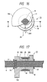
- Fig. 16 is a side view of the spring clutch 23 provided on the sheet supply roller shaft 6, and Fig. 17 is a sectional view taken along the line 17 - 17 of Fig. 16.
- the sheet supply roller gear 18 is rotatably mounted on the sheet supply roller shaft 6.
- a clutch drum 19 is fitted on the sheet supply roller shaft 6 in a confronting relation to the sheet supply roller gear 18 so that the clutch drum 19 cannot be rotated with respect to the shaft 6 by means of an idle rotation preventing pin 21.
- a cam portion 19A is integrally formed with the clutch drum 19. Stopper members 22, 24 serve to prevent the clutch drum 19 and the sheet supply roller gear 18 from shifting in a thrust direction.
- a coil-shaped clutch spring 25 is wound around a barrel 19B of the clutch drum 19 and a barrel 18B of the sheet supply roller gear 18.
- a control ring 20 surrounds the clutch spring 25.
- a lock lever 20A is integrally formed with the control ring 20.
- a stopper 26 is associated with the lock lever 20A and is driven by a solenoid (not shown).
- the stopper 26 In the clutch-on condition, the stopper 26 is retarded from a movement path of the lock lever 20A of the control ring 20, thereby permitting the rotation of the control ring 20.
- the clutch spring 25 is tightened against the barrel 18B of the sheet supply roller gear 18, so that the sheet supply roller gear 18 is integrally connected to the clutch drum 19 via the clutch spring 25, with the result that the rotational force of the gear 18 is transmitted to the shaft 6 to rotate it together with the sheet supply roller gear 18, thereby rotating the sheet supply roller 5.
- the stopper 26 When a print signal is inputted to a control circuit (not shown) of the recording apparatus, the stopper 26 is retracted to release the spring clutch 23, thereby creating the clutch-on condition. Further, the motor 13 is rotated in the normal direction. As a result, the sheet supply roller 5 is rotated in the normal direction and the convey roller 1 is also rotated in the normal direction. Further, the downward biasing of the pressure plate 10 is released by rotation of the cam 19A, with the result that the pressure plate is lifted by the pressure plate spring 11 to urge a front end portion of the sheet stack 12 against a cylindrical peripheral portion of the sheet supply roller 5 which is now being rotated normally.
- an uppermost sheet in the sheet stack 12 is picked up and conveyed by the further rotation of the sheet supply roller to be sent to the convey roller 1. If the other sheet(s) is picked up together with the uppermost sheet, the friction piece 8 serves to prevent the other sheet(s) from being sent to the convey roller.
- the motor 13 In order to prevent the skew-feed of the sheet, after a tip end of the sheet supplied by the sheet supply roller 5 passes through a nip between the convey roller 1 and the pinch roller 2, when the sheet is conveyed in the sheet conveying direction by a predetermined amount in a condition that the sheet stack is urged against the sheet supply roller by means of the pressure plate, the motor 13 is rotated reversely. By doing so, since the clutch spring is loosen not to transmit the driving force to the sheet supply roller 5, the tip end of the sheet is returned to the nip between the convey roller 1 and the pinch roller 2 in a condition that a rear end portion of the sheet is held by the sheet supply roller 5. Then, the motor 13 is rotated normally again.
- the spring clutch is used to prevent the skew-feed of the sheet, after the tip end of the sheet passes through the nip between the convey roller and the pinch roller, the sheet must be returned in the reverse direction and then be conveyed in the normal direction again.
- the picked-up sheet is supplied greatly obliquely, a portion of the sheet will not be completely returned to the nip between the convey roller and the pinch roller during the reverse movement of the sheet, with the result that, even when the skew-feed preventing control is effected, the skew-feed of the sheet is not completely corrected.
- an amount of the reverse movement of the sheet may be increased; in this case, however, a distance between the sheet supply roller and the convey roller must be increased, thus making the compactness of the apparatus difficult.
- the object of the present invention is to provide a sheet convey apparatus having a supply means capable of preventing skew-feed of a sheet with high reliability.
- the sheet convey apparatus comprises a convey roller for conveying a sheet, an urging roller urged against the convey roller to generate a conveying force, a sheet containing portion arranged upstream of the convey roller in a sheet conveying direction for accommodating the sheets, a sheet supply roller for picking up the sheet from the sheet containing portion and for sending the sheet toward the convey roller, a drive shaft for generating a driving force for driving the convey roller and the sheet supply roller, a planetary gear to which the driving force is transmitted from a gear on the drive shaft and which can be engaged by a sheet supply roller gear on a shaft of the sheet supply roller to transmit the driving force to the sheet supply roller when the drive shaft is rotated in a direction opposite to the sheet conveying direction and can be engaged by a convey roller gear on a shaft of the convey roller to transmit the driving force to the convey roller when the drive shaft is rotated in the sheet conveying direction, and control means for controlling rotation of the drive shaft in such a manner that the drive shaft is firstly rotated in the direction opposite to
- Fig. 1 shows an example of a serial recording apparatus to which a sheet convey apparatus according to the present invention is applied and is a sectional view of the recording apparatus in which a recording material (sheet) is conveyed only in one direction.
- the recording apparatus comprises a first convey roller 26, a pinch roller 2 urged against the convey roller 26 to generate a conveying force, a pinch roller holder 3 for holding the pinch roller 2, a pinch roller spring 4 for biasing the pinch roller holder 3 to urge the pinch roller 2 against the convey roller to generate a conveying force, a sheet supply roller 5 having a sheet supply roller shaft 6, a second convey roller 27 disposed between the first convey roller 26 and the sheet supply roller 5 and having a roller shaft 28, a driven roller 35 urged against the second convey roller 27 to generate a conveying force, and a spring 36 for biasing the driven roller 35 against the second convey roller.
- the recording apparatus includes a sheet supply cassette 32 in which recording materials are stacked, an urging roller 33 held by the sheet supply cassette and urged against the second convey roller 27 to generate a conveying force, an urging spring 34 for urging the urging roller 33 against the second convey roller, a pressure plate 10 disposed in the sheet supply cassette to urge the sheet stack accommodated in the cassette against the sheet supply roller, a pressure plate spring 11 for biasing the pressure plate 10 toward the sheet supply roller, a separation pawl 47, a sheet discharge roller 30 for discharging the recording material on which an image was recorded, a transmission roller 29 contacted with peripheral surfaces of the first convey roller 26 and the discharge roller 30 to transmit a rotational force of the first convey roller 26 to the discharge roller 30, a driven roller 31 abutted against the discharge roller 30, and a discharge sheet stacker 39 on which the recording materials on which the images were formed are stacked.
- the recording apparatus further includes an ink jet recording head 40, an ink tank 43, a carriage 41 on which the ink jet recording head 40 and the ink tank 43 are mounted and which can be shifted in a main scan direction, a head cover 42 engaged by the carriage 41 to hold the ink jet recording head 40 and the ink tank 43 on the carriage, guide shafts 44, 45 along which the carriage is shifted, and a chassis 46 to which the guide shafts 44, 45 are attached.
- the ink jet recording head 40 used in the illustrated embodiment has heat generating elements disposed in nozzles and is designed so that a bubble is created in ink by thermal energy given from the selectively energized heat generating element and an ink droplet is discharged from the nozzle by the growth of the bubble.
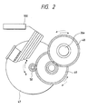
- Figs. 2 to 4 are views for explaining a driving force transmitting mechanism of a convey system of the recording apparatus.
- the driving force transmitting mechanism includes a drive motor 47, a motor gear 58, an idle gear 49 having two different diameter gear portions, and a roller gear 48 mounted on a roller shaft 26a of the first convey roller 26. As shown, the first convey roller is driven by the drive motor 47.
- the reference numeral 100 denotes a control circuit for controlling the drive motor 47.
- the driving force transmitting mechanism further includes a second roller gear 50 mounted on the roller shaft 26a of the first convey roller 26, a planetary gear 52 meshed with the second roller gear 50 to transmit the driving force from the second roller gear to the planetary gear, a holding member 51 rotatably mounted on the roller shaft 26a of the first convey roller 26 and adapted to hold the planetary gear 52, a convey roller gear 53 mounted on the roller shaft 28 of the second convey roller, a sheet supply roller gear 55 mounted on the sheet supply roller shaft 6, and an idle gear 54.
- the planetary gear 52 serves to be meshed with the roller gear 53 on the second convey roller shaft 28 to transmit the driving force of the first convey roller 26 to the second convey roller 27 when the first convey roller 26 is rotated in the sheet conveying direction (Fig. 3) and to be meshed with the idle gear 54 to transmit the driving force of the first convey roller 26 to the sheet supply roller 5 when the first convey roller 26 is rotated in a direction opposite to the sheet conveying direction (Fig. 4).
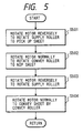
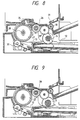
- Fig. 5 shows a sequence of the sheet supplying operation of this apparatus, and the sheet supplying operation will be explained with reference to Figs. 6 to 10.
- the drive motor 47 When the sheet supplying operation is started, the drive motor 47 is rotated in the direction opposite to the sheet conveying direction (reverse direction) by a predetermined number of pulses. As a result, the driving force is transmitted from the first convey roller 26 to the sheet supply roller 5 via the planetary gear 52, thereby rotating the sheet supply roller 5 to pick up the recording material (step S501, Fig. 6).
- the drive motor is rotated reversely by the predetermined number of pulses, the tip end of the recording material is abutted against a nip between the second convey roller 27 and the urging roller 33 which are now stopped, and the trailing end of the recording material is held by the sheet supply roller 5, thereby forming a loop in the recording material (Fig. 7).
- the drive motor 47 is rotated in the normal direction by a predetermined amount.
- the sheet supply roller 5 is stopped and the second convey roller 27 is rotated in the sheet conveying direction. Due to this operation, the tip end of the recording material is pulled by the second convey roller 27 and the urging roller 33 so that the recording material can be conveyed in the sheet conveying directio: by the second convey roller 27.
- the tip end of the recording material is pulled by the second convey roller 27 in a condition that the tip end of the recording material is abutted against the nip between the second convey roller 27 and the urging roller 33 and the loop is formed in the recording material, i.e. in a condition that the tip end of the recording material is aligned with the nip between the second convey roller 27 and the urging roller 33, the skew-feed of the recording material can be corrected with high accuracy and reliability (step S502, Fig. 8).
- the number of pulses applied to the drive motor during its normal rotation is desirably selected so that the second convey roller 27 is not rotated excessively so as to apply a tension force to the recording material between the sheet supply roller 5 and the second convey roller 27.
- the drive motor 47 is rotated again in the direction opposite to the sheet conveying direction to return the sheet supply roller to its original position (step S503, Fig. 9). Then, the drive motor 47 is rotated in the normal direction to rotate the second convey roller 27 in the sheet conveying direction to convey the recording material, by the first convey roller 26, to a recording position, where an image is recorded on the recording material by the recording head 40 (step S504, Fig. 10).
- the good sheet supplying ability can be obtained with inexpensive arrangement.
- a driving force transmitting mechanism can supply a recording material both in a normal direction and in a reverse direction.
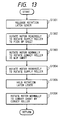
- Figs. 11 and 12 show an arrangement of the driving force transmitting mechanism
- Fig. 13 shows an operating sequence of the mechanism.
- the driving force transmitting mechanism includes a second roller gear 50 mounted on the roller shaft 26a of the first convey roller 26, a planetary gear 52 meshed with the second roller gear 50 to transmit a driving force from the second roller gear to the planetary gear, a lever 56 rotatably mounted on the first convey roller shaft 26a and having a portion for holding the planetary gear 52, a lever holding means 57 for preventing and permitting rotation of the lever 56, which holding means is rocked by an electromagnetic solenoid (not shown) and the like, a convey roller gear 53 mounted on the second convey roller shaft 28, a sheet supply roller gear 55 mounted on the sheet supply roller shaft 6, and an idle gear 54.
- the planetary gear 53 serves to be meshed with the roller gear 53 on the second convey roller shaft 28 to transmit the driving force from the first convey roller 26 to the second convey roller 27 when the first convey roller is rotated in the sheet conveying direction (normal direction) and be meshed with the idle roller 54 to transmit the driving force from the first convey roller 26 to the sheet supply roller 5 when the first convey roller 26 is rotated in the direction opposite to the sheet conveying direction (reverse direction) (Fig. 12).
- Fig. 13 shows the sheet supplying operation effected by this apparatus.
- the lever 56 is released from the lever holding means 57 by means of the solenoid (step S1301).
- the drive motor is rotated in the direction opposite to the sheet conveying direction (reverse direction) by a predetermined number of pulses.
- the driving force is transmitted from the first convey roller 26 to the sheet supply roller 5 via the planetary gear 52, thereby rotating the sheet supply roller 5 to pick up the recording material (step S1302).
- the drive motor 47 is rotated in the normal direction by a predetermined amount.
- the sheet supply roller 5 is stopped and the second convey roller 27 is rotated in the sheet conveying direction. Due to this operation, the tip end of the recording material is pulled by the second convey roller 27 and the urging roller 33 so that the recording material can be conveyed in the sheet conveying direction by the second convey roller 27.
- the tip end of the recording material is pulled by the second convey roller 27 in a condition that the tip end of the recording material is abutted against the nip between the second convey roller 27 and the urging roller 33 and the loop is formed in the recording material, i.e. in a condition that the tip end of the recording material is aligned with the nip between the second convey roller 27 and the urging rolle: 33, the skew-feed of the recording material can be corrected with high accuracy and reliability (step S1303).
- the number of pulses applied to the drive motor during its normal rotation is desirably selected so that the second convey roller 27 is not rotated excessively so as to apply a tension force to the recording material between the sheet supply roller 5 and the second convey roller 27 which are now stopped.
- the drive motor 47 is rotated again in the direction opposite to the sheet conveying direction to return the sheet supply roller to its original position (step S1304). Then, the drive motor 47 is rotated in the normal direction until the planetary gear is engaged by the roller gear 53. Then, the solenoid is turned OFF so that the lever 56 is held by the lever holding means 57 (step S1305). Then, the second convey roller is rotated in the sheet conveying direction to convey the recording material, by the first convey roller 26, to a recording position, where an image is recorded on the recording material by the recording head 40 (step S1306).
- the good sheet supplying ability can be obtained with inexpensive arrangement.
- a sheet convey apparatus having an inexpensive sheet supply means capable of preventing the skew-feed of the sheet with high reliability.
- a sheet convey apparatus comprises first convey means for conveying a sheet, second convey means for pinching and conveying the sheet conveyed by the first convey means, and a drive rotary member shiftable between a first position where the first convey means is driven by the drive rotary member and a second position where the second convey means is driven by the drive rotary member. After a tip end of the sheet conveyed by the first convey means is abutted against a nip of the second convey means to correct skew-feed of the sheet, the sheet is conveyed by the second convey means.
Landscapes
- Engineering & Computer Science (AREA)
- Multimedia (AREA)
- Signal Processing (AREA)
- Mechanical Engineering (AREA)
- Delivering By Means Of Belts And Rollers (AREA)
- Sheets, Magazines, And Separation Thereof (AREA)
- Registering Or Overturning Sheets (AREA)
- Iron Core Of Rotating Electric Machines (AREA)
Claims (18)
- Blattbeförderungsgerät mitdadurch gekennzeichnet, dasseiner Zufuhreinrichtung (5, 6) zum Befördern eines Blatts;einer ersten Beförderungseinrichtung (27, 33) zum Einklemmen und Befördern des durch die Zufuhreinrichtung (5, 6) beförderten Blatts, wobei die erste Beförderungseinrichtung eine erste Walze (27) umfasst und das Blatt durch die erste Beförderungseinrichtung (27, 33) befördert wird, nachdem ein Vorderende des durch die Zufuhreinrichtung (5, 6) beförderten Blatts an einen Spalt der ersten Beförderungseinrichtung (27, 33) angelegt wurde, um eine Schrägzufuhr des Blatts zu korrigieren;einer zweiten Beförderungseinrichtung (2, 26), die in Blattbeförderungsrichtung hinter der ersten Beförderungseinrichtung (27, 33) angeordnet ist und eine zweite Walze (26) aufweist, die auf derselben Seite der Blattbeförderungsbahn wie die erste Walze (27) angeordnet ist;einer Antriebswelle (26a) zum Antreiben der Zufuhreinrichtung (5, 6) und der ersten Beförderungseinrichtung (27, 33); undeinem Antriebsdrehbauteil (52), das mit der Antriebswelle (26a) in Eingriff ist und das zwischen einer ersten Position, in der das Antriebsdrehbauteil (52) die Zufuhreinrichtung (5, 6) antreibt, und einer zweiten Position, in der das Antriebsdrehbauteil (52) mit einem ersten Walzenzahnrad (53) auf einer Welle (28) der ersten Walze (27) kämmt, verschiebbar ist;
die zweite Walze (26) auf der Antriebswelle (26a) befestigt ist, wobei sich sowohl die erste Walze (27) als auch die zweite Walze (26) in derselben Richtung drehen, wenn sich das Antriebsdrehbauteil (52) in der zweiten Position befindet. - Blattbeförderungsgerät nach Patentanspruch 1, wobei die Zufuhreinrichtung (5, 6) eine Zufuhrwalze (5) zum Herausführen eines einzelnen Blatts von einem Blattstapel (12) aufweist.
- Blattbeförderungsgerät nach Patentanspruch 2, wobei die Zufuhrwalze (5) einen Zufuhrabschnitt, der mit dem Blatt in Berührung gebracht werden kann, und einen Nicht-Zufuhrabschnitt aufweist, der nicht mit dem Blatt in Berührung steht.
- Blattbeförderungsgerät nach einem der Patentansprüche 1 bis 3, wobei die Beförderungseinrichtung (27, 33) ein Paar Beförderungswalzen aufweist.
- Blattbeförderungsgerät nach einem der Patentansprüche 1 bis 4, außerdem mit einer Steuereinrichtung (100) zum Steuern des Antriebsdrehbauteils (52) auf eine derartige Weise, dass das Antriebsdrehbauteil (52) die Zufuhreinrichtung (5, 6) in der ersten Position antreibt, um das Blatt an den Spalt der ersten Beförderungseinrichtung (27, 33) anzulegen, die nun gestoppt ist, wodurch eine Schleife im Blatt ausgebildet wird, und das Antriebsdrehbauteil (52) dann zur zweiten Position verschoben wird, an der die erste Beförderungseinrichtung (27, 33) durch das Antriebsdrehbauteil (52) um einen vorbestimmten Betrag angetrieben wird, und das Antriebsdrehbauteil (52) dann wieder zur ersten Position verschoben wird, an der die Zufuhreinrichtung (27, 33) durch das Antriebsdrehbauteil (52) angetrieben wird.
- Blattbeförderungseinrichtung nach einem der Patentansprüche 1 bis 5, wobei das Antriebsdrehbauteil ein Planetenzahnrad (52) aufweist, das mit einem Sonnenzahnrad (50) kämmt.
- Blattbeförderungsgerät nach Patentanspruch 6, außerdem mit einem ersten Zahnrad (54), das mit dem Planetenzahnrad (52) in Eingriff zu bringen ist, um zum Übertragen einer Antriebskraft auf die Zufuhreinrichtung (5, 6) gedreht zu werden, wenn das Antriebsdrehbauteil (52) in der ersten Position ist, und einem ersten Zahnrad (53), das mit dem Planetenzahnrad (52) in Eingriff zu bringen ist, um zum Übertragen einer Antriebskraft auf die erste Beförderungseinrichtung (27, 33) gedreht zu werden, wenn das Antriebsdrehbauteil (52) in der zweiten Position ist.
- Blattbeförderungsgerät nach Patentanspruch 7, wobei das Antriebsdrehbauteil (52) zur ersten Position verschoben wird, wenn es in einer ersten Richtung gedreht wird, und zur zweiten Position verschoben wird, wenn es in einer der ersten Richtung entgegengesetzten zweiten Richtung gedreht wird.
- Blattbeförderungsgerät nach Patentanspruch 8, wobei das Antriebsdrehbauteil (52) in der ersten Richtung gedreht wird, wenn es sich in der ersten Position befindet, wodurch die Zufuhreinrichtung (5, 6) angetrieben wird, um das Blatt zur ersten Beförderungseinrichtung (27, 33) zu schicken, und in der zweiten Richtung gedreht wird, wenn es sich in der zweiten Position befindet, wodurch die erste Beförderungseinrichtung (27, 33) angetrieben wird, so dass das Blatt in stromabwärtiger Richtung befördert wird.
- Blattbeförderungsgerät mitdadurch gekennzeichnet, dasseiner Zufuhrwalze (5) zum Aufnehmen eines Blattes von einem Blätter-enthaltenden Abschnitt (10) und zum Schicken des Blattes zu einer ersten Walze (27);einer gegen die erste Walze (27) gedrückten Druckwalze (33);einer zweiten Walze (26), die in Blattbeförderungsrichtung hinter der ersten Walze (27) und auf derselben Seite der Blattbeförderungsbahn wie die erste Walze (27) angeordnet ist;einem in Blattbeförderungsrichtung stromaufwärts der ersten Walze (27) angeordneten Blätter-enthaltenden Abschnitt (10) zum Aufnehmen der Blätter;einer Antriebswelle (26a) zum Antreiben der ersten Walze (27) und der Zufuhrwalze (5);einem Zahnrad (52), auf das die Antriebskraft von einem Sonnenzahnrad (50) auf der Antriebswelle (26a) übertragen wird und das die Antriebskraft auf ein Zufuhrwalzenzahnrad (55) auf einer Welle (6) der Zufuhrwalze (5) übertragen kann, um die Antriebskraft auf die Zufuhrwalze (5) zu übertragen, wenn die Antriebswelle (26a) in entgegengesetzter Richtung der Blattbeförderungsrichtung gedreht wird, und das mit einem ersten Walzenzahnrad (53) auf einer Welle (28) der ersten Walze (27) in Eingriff gebracht werden kann, um die Antriebskraft auf die erste Walze (27) zu übertragen, wenn die Antriebswelle (26a) in Blattbeförderungsrichtung gedreht wird;einer Steuereinrichtung (100) zum Steuern der Drehung der Antriebswelle (26a) auf eine derartige Weise, dass die Antriebswelle (26a) zuerst in entgegengesetzter Richtung der Blattbeförderungsrichtung gedreht wird, um die Zufuhrwalze (5) zu drehen, wodurch das Blatt vom Blätter-enthaltenden Abschnitt (10) aufgenommen und an einen Spalt zwischen der ersten Walze (27) und der Druckwalze (33) angelegt wird, die nun gestoppt sind, und die Antriebswelle (26a) dann in Blattbeförderungsrichtung gedreht wird;
das Zahnrad (52) ein Planetenzahnrad ist, das mit dem Sonnenzahnrad (50) kämmt, und die zweite Walze (26) auf der Antriebswelle (26a) befestigt ist, so dass sowohl die erste Walze (27) als auch die zweite Walze (26) sich in derselben Richtung drehen, wenn das Zahnrad (52) mit dem ersten Walzenzahnrad (53) in Eingriff ist. - Blattbeförderungsgerät nach Patentanspruch 10, wobei die Zufuhrwalze (5) eine halbkreisförmige Zufuhrwalze umfasst und wobei die Antriebswelle (26a) in entgegengesetzter Richtung der Blattbeförderungsrichtung gedreht wird, um die Zufuhrwalze (5) zu drehen, damit das Blatt vom Blätter-enthaltenden Abschnitt (10) aufgenommen und an den Spalt zwischen der ersten Walze (27) und der Druckwalze (33) angelegt wird, die nun gestoppt sind, und die Antriebswelle (26a) dann in einem Zustand, in dem das Blatt gegen die Zufuhrwalze (5) gedrückt ist, wodurch das Blatt zwischen die erste Walze (27) und die Druckwalze (33) geklemmt wird, in Blattbeförderungsrichtung gedreht wird, um das Blatt um einen vorbestimmten Betrag zu befördern, und die Antriebswelle (26a) dann wieder in entgegengesetzter Richtung der Blattbeförderungsrichtung gedreht wird, wodurch die Zufuhrwalze (5) zu einer vorbestimmten Position gedreht wird, und die Antriebswelle (26a) dann in Blattbeförderungsrichtung gedreht wird, wodurch ein Blattzufuhrbetrieb erfolgt.
- Blattbeförderungsgerät mitdadurch gekennzeichnet, dasseiner Zufuhrwalze (5) zum Aufnehmen eines Blattes von einem Blätter-enthaltenden Abschnitt (10) und zum Schicken des Blattes zu einer ersten Walze (27) zum Befördern des Blattes;einer gegen die erste Walze (27) gedrückten Druckwalze (33);einer zweiten Walze (26), die in Blattbeförderungsrichtung hinter der ersten Walze (27) und auf derselben Seite des Beförderungswegs wie die erste Walze (27) angeordnet ist;einem in Blattbeförderungsrichtung stromaufwärts der ersten Walze (27) angeordneten Blätter-enthaltenden Abschnitt (10) zum Aufnehmen der Blätter;einer Antriebswelle (26a) zum Antreiben der ersten Walze (27) und der Zufuhrwalze (5);einem Zahnrad (52), auf das die Antriebskraft von einem Sonnenzahnrad (50) auf der Antriebswelle (26a) übertragen wird und das mit einem Zufuhrwalzenzahnrad(55) auf einer Welle (6) der Zufuhrwalze (5) in Eingriff gebracht werden kann, um die Antriebskraft auf die Zufuhrwalze (5) zu übertragen, wenn die Antriebswelle (26a) in entgegengesetzter Richtung der Blattzufuhrrichtung gedreht wird, und das die Antriebskraft auf ein erstes Walzenzahnrad (53) auf einer Welle (28) der ersten Walze (27) übertragen kann, um die Antriebskraft auf die erste Walze (27) zu übertragen, wenn die Antriebswelle (26a) in Blattbeförderungsrichtung gedreht wird;das Zahnrad (52) ein Planetenzahnrad ist, das mit dem Sonnenzahnrad (50) kämmt, und die zweite Walze (26) auf der Antriebswelle (26a) befestigt ist, so dass sich sowohl die erste Walze (27) als auch die zweite Walze (26) in derselben Richtung drehen, wenn das Zahnrad (52) mit dem ersten Walzenzahnrad (53) in Eingriff ist, und dass das Gerät Folgendes aufweist:einen Hebel (56) zum Halten des Planetenzahnrads (52), wobei der Hebel einen sich frei auf der Antriebswelle (26a) drehenden Lagerabschnitt aufweist;eine Hebelhalteeinrichtung (57) zum Halten des Hebels (56) an einer vorbestimmten Position; wobei das Planetenzahnrad (52) normalerweise mittels des Hebels (56) und der Hebelhalteeinrichtung (57) mit dem ersten Walzenzahnrad (53) in Eingriff ist und wobei der Hebel (56), nur wenn ein Blattzufuhrbetrieb erfolgt, durch Freigeben der Hebelhalteeinrichtung (57) freigegeben wird und die Antriebswelle (26a) in entgegengesetzter Richtung der Blattbeförderungsrichtung gedreht wird, um die Zufuhrwalze (5) zu drehen, damit das Blatt vom Blätter-enthaltenden Abschnitt (10) aufgenommen und an den Spalt zwischen der ersten Walze (27) und der Druckwalze (33) angelegt wird, die nun gestoppt sind, und die Antriebswelle (26) dann in Blattbeförderungsrichtung gedreht wird.
- Blattbeförderungsgerät nach Patentanspruch 12, wobei die Zufuhrwalze (5) eine halbkreisförmige Blattzufuhrwalze umfasst und wobei der Hebel (56), nur wenn ein Blattzufuhrbetrieb ausgeführt wird, durch Freigeben der Hebelhalteeinrichtung (57) freigegeben wird und die Antriebswelle (26) in entgegengesetzter Richtung der Blattbeförderungsrichtung gedreht wird, um die Zufuhrwalze (5) zu drehen, damit das Blatt vom Blätter-enthaltenden Abschnitt (10) aufgenommen und an den Spalt zwischen der ersten Walze (27) und der Druckwalze (33) angelegt wird, die nun gestoppt sind, und die Antriebswelle (26a) dann in einem Zustand, in dem das Blatt gegen die Zufuhrwalze (5) gedrückt ist, wodurch das Blatt zwischen die erste Walze (27) und die Druckwalze (33) geklemmt wird, in Blattbeförderungsrichtung gedreht wird, um das Blatt um einen vorbestimmten Betrag zu befördern, und die Antriebswelle (26a) dann wieder in entgegengesetzter Richtung der Blattbeförderungsrichtung gedreht wird, wodurch die Zufuhrwalze (5) zu einer vorbestimmten Position gedreht wird, und die Antriebswelle (26a) dann ih Blattbeförderungsrichtung gedreht wird, wodurch ein Blattzufuhrbetrieb erfolgt.
- Bilderzeugungsgerät miteinem Blattbeförderungsgerät nach einem der Patentansprüche 1 bis 13, undeiner Bilderzeugungseinrichtung zum Erzeugen eines Bildes auf einem durch die erste Walze (27) beförderten Blatt.
- Bilderzeugungsgerät nach Patentanspruch 14, wobei die Bilderzeugungseinrichtung einen Tintenstrahlkopf (40) aufweist.
- Bilderzeugungsgerät nach Patentanspruch 15, wobei der Tintenstrahlkopf (40) das Bild auf dem Blatt durch Ausstoßen eines Tintentröpfchens unter Verwendung thermischer Energie ausbildet.
- Blattbeförderungsgerät nach einem der Patentansprüche 1 bis 11, mit außerdem einer Halteeinrichtung (57) zum Halten des Antriebsdrehbauteils (52) an der zweiten Position.
- Blattbeförderungsgerät nach Patentanspruch 10 oder 12, wobei das Zahnrad (52) die Antriebskraft über ein Leerlaufzahnrad (54) auf das Zufuhrwalzenzahnrad (55) überträgt.
Applications Claiming Priority (3)
| Application Number | Priority Date | Filing Date | Title |
|---|---|---|---|
| JP117167/93 | 1993-05-19 | ||
| JP11716793 | 1993-05-19 | ||
| JP05117167A JP3126548B2 (ja) | 1993-05-19 | 1993-05-19 | 記録媒体搬送装置 |
Publications (2)
| Publication Number | Publication Date |
|---|---|
| EP0625840A1 EP0625840A1 (de) | 1994-11-23 |
| EP0625840B1 true EP0625840B1 (de) | 2001-04-11 |
Family
ID=14705110
Family Applications (1)
| Application Number | Title | Priority Date | Filing Date |
|---|---|---|---|
| EP94107694A Expired - Lifetime EP0625840B1 (de) | 1993-05-19 | 1994-05-18 | Apparat zum Fördern von Blättern |
Country Status (5)
| Country | Link |
|---|---|
| US (1) | US6139010A (de) |
| EP (1) | EP0625840B1 (de) |
| JP (1) | JP3126548B2 (de) |
| AT (1) | ATE200600T1 (de) |
| DE (1) | DE69427049T2 (de) |
Families Citing this family (14)
| Publication number | Priority date | Publication date | Assignee | Title |
|---|---|---|---|---|
| JP3190247B2 (ja) * | 1996-03-13 | 2001-07-23 | キヤノン株式会社 | シート材給送装置及び画像形成装置 |
| JP3763253B2 (ja) * | 2000-09-29 | 2006-04-05 | ブラザー工業株式会社 | 画像形成装置 |
| KR100383698B1 (ko) * | 2001-04-12 | 2003-05-14 | 주식회사 에프엘테크놀로지 | 현금자동지급기 |
| JP3880510B2 (ja) | 2002-01-24 | 2007-02-14 | キヤノン株式会社 | 記録装置および記録媒体の種類判別方法 |
| JP3919549B2 (ja) * | 2002-01-31 | 2007-05-30 | キヤノン株式会社 | 記録装置 |
| US6749192B2 (en) * | 2002-06-05 | 2004-06-15 | Hewlett-Packard Development Company, L.P. | Skew correction for a media feed mechanism |
| KR100513753B1 (ko) * | 2003-04-15 | 2005-09-09 | 삼성전자주식회사 | 사무기기의 급지장치 |
| US7451975B2 (en) * | 2004-03-18 | 2008-11-18 | Lexmark International, Inc. | Input tray and drive mechanism using a single motor for an image forming device |
| KR100561432B1 (ko) * | 2004-06-16 | 2006-03-17 | 삼성전자주식회사 | 용지급지장치 및 이를 구비한 화상형성장치 |
| JP4396587B2 (ja) * | 2005-06-22 | 2010-01-13 | ブラザー工業株式会社 | 画像形成装置 |
| US7549626B2 (en) * | 2005-09-08 | 2009-06-23 | Lexmark International, Inc. | Media timing based on stack height for use within an image forming device |
| KR101053728B1 (ko) * | 2008-01-21 | 2011-08-02 | 엘지엔시스(주) | 매체자동지급기의 매체분리장치 |
| JP6547539B2 (ja) * | 2015-09-16 | 2019-07-24 | ブラザー工業株式会社 | 画像形成装置 |
| JP6758942B2 (ja) | 2016-06-17 | 2020-09-23 | キヤノン株式会社 | 搬送装置およびプリント装置 |
Family Cites Families (15)
| Publication number | Priority date | Publication date | Assignee | Title |
|---|---|---|---|---|
| JPS5430184B2 (de) * | 1973-12-27 | 1979-09-28 | ||
| JPS5931943B2 (ja) * | 1979-04-02 | 1984-08-06 | キヤノン株式会社 | 液体噴射記録法 |
| JPS586660A (ja) * | 1981-07-06 | 1983-01-14 | Fuji Photo Film Co Ltd | 画像走査装置 |
| CH663601A5 (de) * | 1982-10-06 | 1987-12-31 | Kurt Ruenzi | Verfahren und transportvorrichtung zur zufuhr von blattfoermigem abdruckmaterial zu einer bueromaschine. |
| US4581618A (en) * | 1983-03-09 | 1986-04-08 | Canon Kabushiki Kaisha | Recorder having paper feed mechanism |
| US4529188A (en) * | 1983-07-05 | 1985-07-16 | Xerox Corporation | Sheet feeding and registration apparatus |
| JPS61145046A (ja) * | 1984-12-20 | 1986-07-02 | Ricoh Co Ltd | 給紙装置 |
| JPS61226441A (ja) * | 1985-03-30 | 1986-10-08 | Tokyo Juki Ind Co Ltd | 単葉給紙装置 |
| JPH07106801B2 (ja) * | 1985-07-31 | 1995-11-15 | セイコーエプソン株式会社 | 給紙装置 |
| JPH0674097B2 (ja) * | 1985-11-08 | 1994-09-21 | ブラザー工業株式会社 | プリンタの給紙装置 |
| JPH0789638B2 (ja) * | 1986-12-11 | 1995-09-27 | 株式会社テック | ファクシミリの紙送り装置 |
| US4884909A (en) * | 1986-12-25 | 1989-12-05 | Canon Kabushiki Kaisha | Recording apparatus |
| US4953037A (en) * | 1988-02-05 | 1990-08-28 | Canon Kabushiki Kaisha | Original reading apparatus |
| US5211690A (en) * | 1988-12-23 | 1993-05-18 | Canon Kabushiki Kaisha | Transmission clutch and recording apparatus which uses the transmission clutch |
| US5184902A (en) * | 1989-11-26 | 1993-02-09 | Canon Kabushiki Kaisha | Recording apparatus having a single drive source for conveying recording means and feeding recording medium |
-
1993
- 1993-05-19 JP JP05117167A patent/JP3126548B2/ja not_active Expired - Fee Related
-
1994
- 1994-05-18 AT AT94107694T patent/ATE200600T1/de not_active IP Right Cessation
- 1994-05-18 DE DE69427049T patent/DE69427049T2/de not_active Expired - Lifetime
- 1994-05-18 EP EP94107694A patent/EP0625840B1/de not_active Expired - Lifetime
-
1997
- 1997-02-24 US US08/804,756 patent/US6139010A/en not_active Expired - Lifetime
Also Published As
| Publication number | Publication date |
|---|---|
| EP0625840A1 (de) | 1994-11-23 |
| JPH06329305A (ja) | 1994-11-29 |
| DE69427049D1 (de) | 2001-05-17 |
| DE69427049T2 (de) | 2001-08-23 |
| JP3126548B2 (ja) | 2001-01-22 |
| ATE200600T1 (de) | 2001-04-15 |
| US6139010A (en) | 2000-10-31 |
Similar Documents
| Publication | Publication Date | Title |
|---|---|---|
| EP0625840B1 (de) | Apparat zum Fördern von Blättern | |
| JP2000218892A (ja) | 熱転写記録装置 | |
| US5820275A (en) | Printer multi-function drive train apparatus and method | |
| US5480132A (en) | Sheet transport apparatus with disengagement means to allow reverse sheet movement | |
| US4986525A (en) | Sheet feed device for use in a printer or the like | |
| US8646904B2 (en) | Sheet feeding device and recording apparatus | |
| JP2002249248A (ja) | シート給送装置及び記録装置 | |
| KR100449105B1 (ko) | 이송부 동력걸림 해제부를 갖는 사무기기의 구동장치 | |
| US4949638A (en) | Printer using a drum | |
| JP2000085999A (ja) | シート供給装置と該装置を備えた画像形成装置 | |
| JPH10139239A (ja) | ラベルプリンタ | |
| JP2004075277A (ja) | 給送装置およびこの給送装置を備えた記録装置、駆動ギア列 | |
| JP2837974B2 (ja) | 自動給紙装置 | |
| JP2649593B2 (ja) | 自動給紙装置 | |
| JPH05278285A (ja) | サーマルプリンタ | |
| EP0446840B1 (de) | Automatischer Apparat zum Zuführen von Papier | |
| JP2004010266A (ja) | シート材給送装置及び記録装置 | |
| JP2002332130A (ja) | シート材給送装置、シート材給送方法および記録装置 | |
| JPH054397A (ja) | シート給送装置及び前記シート給送装置を有する記録装置 | |
| JP3619013B2 (ja) | シート材給送装置及び画像処理装置 | |
| JP2577166Y2 (ja) | プリンタの給紙装置 | |
| JP2554901B2 (ja) | 自動給紙機構 | |
| JP4761153B2 (ja) | 記録媒体供給装置およびこれを用いた画像形成装置 | |
| JP3722728B2 (ja) | 給紙装置及び画像形成装置 | |
| JP4172110B2 (ja) | 画像プリンタ |
Legal Events
| Date | Code | Title | Description |
|---|---|---|---|
| PUAI | Public reference made under article 153(3) epc to a published international application that has entered the european phase |
Free format text: ORIGINAL CODE: 0009012 |
|
| AK | Designated contracting states |
Kind code of ref document: A1 Designated state(s): AT BE CH DE DK ES FR GB GR IE IT LI LU NL PT SE |
|
| 17P | Request for examination filed |
Effective date: 19950410 |
|
| 17Q | First examination report despatched |
Effective date: 19980325 |
|
| GRAG | Despatch of communication of intention to grant |
Free format text: ORIGINAL CODE: EPIDOS AGRA |
|
| GRAG | Despatch of communication of intention to grant |
Free format text: ORIGINAL CODE: EPIDOS AGRA |
|
| GRAG | Despatch of communication of intention to grant |
Free format text: ORIGINAL CODE: EPIDOS AGRA |
|
| GRAH | Despatch of communication of intention to grant a patent |
Free format text: ORIGINAL CODE: EPIDOS IGRA |
|
| GRAH | Despatch of communication of intention to grant a patent |
Free format text: ORIGINAL CODE: EPIDOS IGRA |
|
| GRAH | Despatch of communication of intention to grant a patent |
Free format text: ORIGINAL CODE: EPIDOS IGRA |
|
| GRAA | (expected) grant |
Free format text: ORIGINAL CODE: 0009210 |
|
| AK | Designated contracting states |
Kind code of ref document: B1 Designated state(s): AT BE CH DE DK ES FR GB GR IE IT LI LU NL PT SE |
|
| PG25 | Lapsed in a contracting state [announced via postgrant information from national office to epo] |
Ref country code: NL Free format text: LAPSE BECAUSE OF FAILURE TO SUBMIT A TRANSLATION OF THE DESCRIPTION OR TO PAY THE FEE WITHIN THE PRESCRIBED TIME-LIMIT Effective date: 20010411 Ref country code: LI Free format text: LAPSE BECAUSE OF FAILURE TO SUBMIT A TRANSLATION OF THE DESCRIPTION OR TO PAY THE FEE WITHIN THE PRESCRIBED TIME-LIMIT Effective date: 20010411 Ref country code: IT Free format text: LAPSE BECAUSE OF FAILURE TO SUBMIT A TRANSLATION OF THE DESCRIPTION OR TO PAY THE FEE WITHIN THE PRESCRIBED TIME-LIMIT;WARNING: LAPSES OF ITALIAN PATENTS WITH EFFECTIVE DATE BEFORE 2007 MAY HAVE OCCURRED AT ANY TIME BEFORE 2007. THE CORRECT EFFECTIVE DATE MAY BE DIFFERENT FROM THE ONE RECORDED. Effective date: 20010411 Ref country code: GR Free format text: LAPSE BECAUSE OF NON-PAYMENT OF DUE FEES Effective date: 20010411 Ref country code: FR Free format text: LAPSE BECAUSE OF FAILURE TO SUBMIT A TRANSLATION OF THE DESCRIPTION OR TO PAY THE FEE WITHIN THE PRESCRIBED TIME-LIMIT Effective date: 20010411 Ref country code: CH Free format text: LAPSE BECAUSE OF FAILURE TO SUBMIT A TRANSLATION OF THE DESCRIPTION OR TO PAY THE FEE WITHIN THE PRESCRIBED TIME-LIMIT Effective date: 20010411 Ref country code: BE Free format text: LAPSE BECAUSE OF FAILURE TO SUBMIT A TRANSLATION OF THE DESCRIPTION OR TO PAY THE FEE WITHIN THE PRESCRIBED TIME-LIMIT Effective date: 20010411 Ref country code: AT Free format text: LAPSE BECAUSE OF FAILURE TO SUBMIT A TRANSLATION OF THE DESCRIPTION OR TO PAY THE FEE WITHIN THE PRESCRIBED TIME-LIMIT Effective date: 20010411 |
|
| REF | Corresponds to: |
Ref document number: 200600 Country of ref document: AT Date of ref document: 20010415 Kind code of ref document: T |
|
| REG | Reference to a national code |
Ref country code: CH Ref legal event code: EP |
|
| REG | Reference to a national code |
Ref country code: IE Ref legal event code: FG4D |
|
| REF | Corresponds to: |
Ref document number: 69427049 Country of ref document: DE Date of ref document: 20010517 |
|
| PG25 | Lapsed in a contracting state [announced via postgrant information from national office to epo] |
Ref country code: LU Free format text: LAPSE BECAUSE OF NON-PAYMENT OF DUE FEES Effective date: 20010518 Ref country code: IE Free format text: LAPSE BECAUSE OF NON-PAYMENT OF DUE FEES Effective date: 20010518 |
|
| PG25 | Lapsed in a contracting state [announced via postgrant information from national office to epo] |
Ref country code: SE Free format text: LAPSE BECAUSE OF FAILURE TO SUBMIT A TRANSLATION OF THE DESCRIPTION OR TO PAY THE FEE WITHIN THE PRESCRIBED TIME-LIMIT Effective date: 20010711 Ref country code: PT Free format text: LAPSE BECAUSE OF FAILURE TO SUBMIT A TRANSLATION OF THE DESCRIPTION OR TO PAY THE FEE WITHIN THE PRESCRIBED TIME-LIMIT Effective date: 20010711 Ref country code: GB Free format text: LAPSE BECAUSE OF NON-PAYMENT OF DUE FEES Effective date: 20010711 Ref country code: DK Free format text: LAPSE BECAUSE OF FAILURE TO SUBMIT A TRANSLATION OF THE DESCRIPTION OR TO PAY THE FEE WITHIN THE PRESCRIBED TIME-LIMIT Effective date: 20010711 |
|
| NLV1 | Nl: lapsed or annulled due to failure to fulfill the requirements of art. 29p and 29m of the patents act | ||
| EN | Fr: translation not filed | ||
| REG | Reference to a national code |
Ref country code: CH Ref legal event code: PL |
|
| PG25 | Lapsed in a contracting state [announced via postgrant information from national office to epo] |
Ref country code: ES Free format text: LAPSE BECAUSE OF FAILURE TO SUBMIT A TRANSLATION OF THE DESCRIPTION OR TO PAY THE FEE WITHIN THE PRESCRIBED TIME-LIMIT Effective date: 20011030 |
|
| PLBE | No opposition filed within time limit |
Free format text: ORIGINAL CODE: 0009261 |
|
| STAA | Information on the status of an ep patent application or granted ep patent |
Free format text: STATUS: NO OPPOSITION FILED WITHIN TIME LIMIT |
|
| GBPC | Gb: european patent ceased through non-payment of renewal fee |
Effective date: 20010711 |
|
| REG | Reference to a national code |
Ref country code: IE Ref legal event code: MM4A |
|
| 26N | No opposition filed | ||
| PGFP | Annual fee paid to national office [announced via postgrant information from national office to epo] |
Ref country code: DE Payment date: 20120531 Year of fee payment: 19 |
|
| PG25 | Lapsed in a contracting state [announced via postgrant information from national office to epo] |
Ref country code: DE Free format text: LAPSE BECAUSE OF NON-PAYMENT OF DUE FEES Effective date: 20131203 |
|
| REG | Reference to a national code |
Ref country code: DE Ref legal event code: R119 Ref document number: 69427049 Country of ref document: DE Effective date: 20131203 |