EP0624474B1 - Têtes d'impression utilisées dans l'impression par jet d'encre et méthode de fabrication - Google Patents
Têtes d'impression utilisées dans l'impression par jet d'encre et méthode de fabrication Download PDFInfo
- Publication number
- EP0624474B1 EP0624474B1 EP19940303424 EP94303424A EP0624474B1 EP 0624474 B1 EP0624474 B1 EP 0624474B1 EP 19940303424 EP19940303424 EP 19940303424 EP 94303424 A EP94303424 A EP 94303424A EP 0624474 B1 EP0624474 B1 EP 0624474B1
- Authority
- EP
- European Patent Office
- Prior art keywords
- resin
- ink
- activation
- hardened
- energy
- Prior art date
- Legal status (The legal status is an assumption and is not a legal conclusion. Google has not performed a legal analysis and makes no representation as to the accuracy of the status listed.)
- Expired - Lifetime
Links
- 238000007639 printing Methods 0.000 title claims description 81
- 238000007641 inkjet printing Methods 0.000 title claims description 44
- 238000004519 manufacturing process Methods 0.000 title claims description 9
- 229920005989 resin Polymers 0.000 claims description 121
- 239000011347 resin Substances 0.000 claims description 121
- 239000000758 substrate Substances 0.000 claims description 66
- -1 acetylene glycol Chemical compound 0.000 claims description 31
- LYCAIKOWRPUZTN-UHFFFAOYSA-N ethylene glycol Natural products OCCO LYCAIKOWRPUZTN-UHFFFAOYSA-N 0.000 claims description 29
- HSFWRNGVRCDJHI-UHFFFAOYSA-N alpha-acetylene Natural products C#C HSFWRNGVRCDJHI-UHFFFAOYSA-N 0.000 claims description 27
- WGCNASOHLSPBMP-UHFFFAOYSA-N hydroxyacetaldehyde Natural products OCC=O WGCNASOHLSPBMP-UHFFFAOYSA-N 0.000 claims description 26
- 230000004913 activation Effects 0.000 claims description 17
- 238000010521 absorption reaction Methods 0.000 claims description 14
- 238000000034 method Methods 0.000 claims description 14
- 238000002835 absorbance Methods 0.000 claims description 12
- 238000010894 electron beam technology Methods 0.000 claims description 12
- 125000003700 epoxy group Chemical group 0.000 claims description 10
- 230000003595 spectral effect Effects 0.000 claims description 8
- 230000001678 irradiating effect Effects 0.000 claims description 4
- 239000000976 ink Substances 0.000 description 81
- 239000000203 mixture Substances 0.000 description 45
- PEDCQBHIVMGVHV-UHFFFAOYSA-N Glycerine Chemical compound OCC(O)CO PEDCQBHIVMGVHV-UHFFFAOYSA-N 0.000 description 21
- MTHSVFCYNBDYFN-UHFFFAOYSA-N diethylene glycol Chemical compound OCCOCCO MTHSVFCYNBDYFN-UHFFFAOYSA-N 0.000 description 19
- XLYOFNOQVPJJNP-UHFFFAOYSA-N water Substances O XLYOFNOQVPJJNP-UHFFFAOYSA-N 0.000 description 10
- 238000011156 evaluation Methods 0.000 description 7
- LFQSCWFLJHTTHZ-UHFFFAOYSA-N Ethanol Chemical compound CCO LFQSCWFLJHTTHZ-UHFFFAOYSA-N 0.000 description 6
- 238000007654 immersion Methods 0.000 description 6
- 239000000853 adhesive Substances 0.000 description 5
- 125000000524 functional group Chemical group 0.000 description 5
- 239000000178 monomer Substances 0.000 description 5
- BDERNNFJNOPAEC-UHFFFAOYSA-N propan-1-ol Chemical compound CCCO BDERNNFJNOPAEC-UHFFFAOYSA-N 0.000 description 5
- PXHVJJICTQNCMI-UHFFFAOYSA-N Nickel Chemical compound [Ni] PXHVJJICTQNCMI-UHFFFAOYSA-N 0.000 description 4
- IISBACLAFKSPIT-UHFFFAOYSA-N bisphenol A Chemical compound C=1C=C(O)C=CC=1C(C)(C)C1=CC=C(O)C=C1 IISBACLAFKSPIT-UHFFFAOYSA-N 0.000 description 4
- 239000003086 colorant Substances 0.000 description 4
- 239000003960 organic solvent Substances 0.000 description 4
- HNJBEVLQSNELDL-UHFFFAOYSA-N pyrrolidin-2-one Chemical compound O=C1CCCN1 HNJBEVLQSNELDL-UHFFFAOYSA-N 0.000 description 4
- SMZOUWXMTYCWNB-UHFFFAOYSA-N 2-(2-methoxy-5-methylphenyl)ethanamine Chemical compound COC1=CC=C(C)C=C1CCN SMZOUWXMTYCWNB-UHFFFAOYSA-N 0.000 description 3
- NIXOWILDQLNWCW-UHFFFAOYSA-N 2-Propenoic acid Natural products OC(=O)C=C NIXOWILDQLNWCW-UHFFFAOYSA-N 0.000 description 3
- CERQOIWHTDAKMF-UHFFFAOYSA-N Methacrylic acid Chemical compound CC(=C)C(O)=O CERQOIWHTDAKMF-UHFFFAOYSA-N 0.000 description 3
- OKKJLVBELUTLKV-UHFFFAOYSA-N Methanol Chemical compound OC OKKJLVBELUTLKV-UHFFFAOYSA-N 0.000 description 3
- ZMXDDKWLCZADIW-UHFFFAOYSA-N N,N-Dimethylformamide Chemical compound CN(C)C=O ZMXDDKWLCZADIW-UHFFFAOYSA-N 0.000 description 3
- DNIAPMSPPWPWGF-UHFFFAOYSA-N Propylene glycol Chemical compound CC(O)CO DNIAPMSPPWPWGF-UHFFFAOYSA-N 0.000 description 3
- 125000000217 alkyl group Chemical group 0.000 description 3
- 235000019241 carbon black Nutrition 0.000 description 3
- 230000000052 comparative effect Effects 0.000 description 3
- 239000000975 dye Substances 0.000 description 3
- 238000009472 formulation Methods 0.000 description 3
- 238000002329 infrared spectrum Methods 0.000 description 3
- 238000006116 polymerization reaction Methods 0.000 description 3
- 239000000080 wetting agent Substances 0.000 description 3
- DNIAPMSPPWPWGF-VKHMYHEASA-N (+)-propylene glycol Chemical compound C[C@H](O)CO DNIAPMSPPWPWGF-VKHMYHEASA-N 0.000 description 2
- YPFDHNVEDLHUCE-UHFFFAOYSA-N 1,3-propanediol Substances OCCCO YPFDHNVEDLHUCE-UHFFFAOYSA-N 0.000 description 2
- 229940035437 1,3-propanediol Drugs 0.000 description 2
- CUVLMZNMSPJDON-UHFFFAOYSA-N 1-(1-butoxypropan-2-yloxy)propan-2-ol Chemical compound CCCCOCC(C)OCC(C)O CUVLMZNMSPJDON-UHFFFAOYSA-N 0.000 description 2
- IUVCFHHAEHNCFT-INIZCTEOSA-N 2-[(1s)-1-[4-amino-3-(3-fluoro-4-propan-2-yloxyphenyl)pyrazolo[3,4-d]pyrimidin-1-yl]ethyl]-6-fluoro-3-(3-fluorophenyl)chromen-4-one Chemical compound C1=C(F)C(OC(C)C)=CC=C1C(C1=C(N)N=CN=C11)=NN1[C@@H](C)C1=C(C=2C=C(F)C=CC=2)C(=O)C2=CC(F)=CC=C2O1 IUVCFHHAEHNCFT-INIZCTEOSA-N 0.000 description 2
- COBPKKZHLDDMTB-UHFFFAOYSA-N 2-[2-(2-butoxyethoxy)ethoxy]ethanol Chemical compound CCCCOCCOCCOCCO COBPKKZHLDDMTB-UHFFFAOYSA-N 0.000 description 2
- RTZKZFJDLAIYFH-UHFFFAOYSA-N Diethyl ether Chemical compound CCOCC RTZKZFJDLAIYFH-UHFFFAOYSA-N 0.000 description 2
- SECXISVLQFMRJM-UHFFFAOYSA-N N-Methylpyrrolidone Chemical compound CN1CCCC1=O SECXISVLQFMRJM-UHFFFAOYSA-N 0.000 description 2
- XSQUKJJJFZCRTK-UHFFFAOYSA-N Urea Chemical compound NC(N)=O XSQUKJJJFZCRTK-UHFFFAOYSA-N 0.000 description 2
- 239000000654 additive Substances 0.000 description 2
- PXKLMJQFEQBVLD-UHFFFAOYSA-N bisphenol F Chemical compound C1=CC(O)=CC=C1CC1=CC=C(O)C=C1 PXKLMJQFEQBVLD-UHFFFAOYSA-N 0.000 description 2
- 239000004202 carbamide Substances 0.000 description 2
- 229940028356 diethylene glycol monobutyl ether Drugs 0.000 description 2
- 239000011521 glass Substances 0.000 description 2
- 239000002184 metal Substances 0.000 description 2
- 229910052751 metal Inorganic materials 0.000 description 2
- 229910052759 nickel Inorganic materials 0.000 description 2
- JCGNDDUYTRNOFT-UHFFFAOYSA-N oxolane-2,4-dione Chemical compound O=C1COC(=O)C1 JCGNDDUYTRNOFT-UHFFFAOYSA-N 0.000 description 2
- 239000000049 pigment Substances 0.000 description 2
- 229920000166 polytrimethylene carbonate Polymers 0.000 description 2
- 239000011342 resin composition Substances 0.000 description 2
- 239000002904 solvent Substances 0.000 description 2
- 229910001220 stainless steel Inorganic materials 0.000 description 2
- 239000010935 stainless steel Substances 0.000 description 2
- ZIBGPFATKBEMQZ-UHFFFAOYSA-N triethylene glycol Chemical compound OCCOCCOCCO ZIBGPFATKBEMQZ-UHFFFAOYSA-N 0.000 description 2
- 125000004178 (C1-C4) alkyl group Chemical group 0.000 description 1
- 125000004169 (C1-C6) alkyl group Chemical group 0.000 description 1
- 229920002818 (Hydroxyethyl)methacrylate Polymers 0.000 description 1
- LYCAIKOWRPUZTN-NMQOAUCRSA-N 1,2-dideuteriooxyethane Chemical compound [2H]OCCO[2H] LYCAIKOWRPUZTN-NMQOAUCRSA-N 0.000 description 1
- CYSGHNMQYZDMIA-UHFFFAOYSA-N 1,3-Dimethyl-2-imidazolidinon Chemical compound CN1CCN(C)C1=O CYSGHNMQYZDMIA-UHFFFAOYSA-N 0.000 description 1
- RWNUSVWFHDHRCJ-UHFFFAOYSA-N 1-butoxypropan-2-ol Chemical compound CCCCOCC(C)O RWNUSVWFHDHRCJ-UHFFFAOYSA-N 0.000 description 1
- ARXJGSRGQADJSQ-UHFFFAOYSA-N 1-methoxypropan-2-ol Chemical compound COCC(C)O ARXJGSRGQADJSQ-UHFFFAOYSA-N 0.000 description 1
- SYEWHONLFGZGLK-UHFFFAOYSA-N 2-[1,3-bis(oxiran-2-ylmethoxy)propan-2-yloxymethyl]oxirane Chemical compound C1OC1COCC(OCC1OC1)COCC1CO1 SYEWHONLFGZGLK-UHFFFAOYSA-N 0.000 description 1
- OMIGHNLMNHATMP-UHFFFAOYSA-N 2-hydroxyethyl prop-2-enoate Chemical compound OCCOC(=O)C=C OMIGHNLMNHATMP-UHFFFAOYSA-N 0.000 description 1
- GNSFRPWPOGYVLO-UHFFFAOYSA-N 3-hydroxypropyl 2-methylprop-2-enoate Chemical compound CC(=C)C(=O)OCCCO GNSFRPWPOGYVLO-UHFFFAOYSA-N 0.000 description 1
- QZPSOSOOLFHYRR-UHFFFAOYSA-N 3-hydroxypropyl prop-2-enoate Chemical compound OCCCOC(=O)C=C QZPSOSOOLFHYRR-UHFFFAOYSA-N 0.000 description 1
- YTNUOGWCFLMGLF-UHFFFAOYSA-N 5-methylbenzene-1,2,3,4-tetrol Chemical compound CC1=CC(O)=C(O)C(O)=C1O YTNUOGWCFLMGLF-UHFFFAOYSA-N 0.000 description 1
- KYARBIJYVGJZLB-UHFFFAOYSA-N 7-amino-4-hydroxy-2-naphthalenesulfonic acid Chemical compound OC1=CC(S(O)(=O)=O)=CC2=CC(N)=CC=C21 KYARBIJYVGJZLB-UHFFFAOYSA-N 0.000 description 1
- JMIFGARJSWXZSH-UHFFFAOYSA-N DMH1 Chemical compound C1=CC(OC(C)C)=CC=C1C1=CN2N=CC(C=3C4=CC=CC=C4N=CC=3)=C2N=C1 JMIFGARJSWXZSH-UHFFFAOYSA-N 0.000 description 1
- WPYCRFCQABTEKC-UHFFFAOYSA-N Diglycidyl resorcinol ether Chemical compound C1OC1COC(C=1)=CC=CC=1OCC1CO1 WPYCRFCQABTEKC-UHFFFAOYSA-N 0.000 description 1
- WOBHKFSMXKNTIM-UHFFFAOYSA-N Hydroxyethyl methacrylate Chemical compound CC(=C)C(=O)OCCO WOBHKFSMXKNTIM-UHFFFAOYSA-N 0.000 description 1
- 239000002202 Polyethylene glycol Substances 0.000 description 1
- 239000002253 acid Substances 0.000 description 1
- 230000000996 additive effect Effects 0.000 description 1
- 150000001298 alcohols Chemical class 0.000 description 1
- 125000002723 alicyclic group Chemical group 0.000 description 1
- 239000003429 antifungal agent Substances 0.000 description 1
- 229940121375 antifungal agent Drugs 0.000 description 1
- 230000005540 biological transmission Effects 0.000 description 1
- 125000004432 carbon atom Chemical group C* 0.000 description 1
- 239000006229 carbon black Substances 0.000 description 1
- 125000003178 carboxy group Chemical group [H]OC(*)=O 0.000 description 1
- 239000002738 chelating agent Substances 0.000 description 1
- 238000004040 coloring Methods 0.000 description 1
- 238000005520 cutting process Methods 0.000 description 1
- 239000000982 direct dye Substances 0.000 description 1
- DHQJMKJYFOHOSY-UHFFFAOYSA-L disodium 4-amino-3-[[4-[4-[(2,4-diaminophenyl)diazenyl]-3-methylphenyl]-2-methylphenyl]diazenyl]-5-oxido-6-phenyldiazenyl-7-sulfonaphthalene-2-sulfonate Chemical compound [Na+].[Na+].Cc1cc(ccc1N=Nc1ccc(N)cc1N)-c1ccc(N=Nc2c(N)c3c(O)c(N=Nc4ccccc4)c(cc3cc2S([O-])(=O)=O)S([O-])(=O)=O)c(C)c1 DHQJMKJYFOHOSY-UHFFFAOYSA-L 0.000 description 1
- 239000003822 epoxy resin Substances 0.000 description 1
- 238000005530 etching Methods 0.000 description 1
- 150000002170 ethers Chemical class 0.000 description 1
- 125000003055 glycidyl group Chemical group C(C1CO1)* 0.000 description 1
- VOZRXNHHFUQHIL-UHFFFAOYSA-N glycidyl methacrylate Chemical compound CC(=C)C(=O)OCC1CO1 VOZRXNHHFUQHIL-UHFFFAOYSA-N 0.000 description 1
- LNEPOXFFQSENCJ-UHFFFAOYSA-N haloperidol Chemical compound C1CC(O)(C=2C=CC(Cl)=CC=2)CCN1CCCC(=O)C1=CC=C(F)C=C1 LNEPOXFFQSENCJ-UHFFFAOYSA-N 0.000 description 1
- 150000002576 ketones Chemical class 0.000 description 1
- 239000007788 liquid Substances 0.000 description 1
- QJGQUHMNIGDVPM-UHFFFAOYSA-N nitrogen group Chemical group [N] QJGQUHMNIGDVPM-UHFFFAOYSA-N 0.000 description 1
- 229920003986 novolac Polymers 0.000 description 1
- 239000012860 organic pigment Substances 0.000 description 1
- RPQRDASANLAFCM-UHFFFAOYSA-N oxiran-2-ylmethyl prop-2-enoate Chemical compound C=CC(=O)OCC1CO1 RPQRDASANLAFCM-UHFFFAOYSA-N 0.000 description 1
- 229920000647 polyepoxide Polymers 0.000 description 1
- 229920001223 polyethylene glycol Polymers 0.000 description 1
- 229920001451 polypropylene glycol Polymers 0.000 description 1
- 239000003755 preservative agent Substances 0.000 description 1
- 230000002335 preservative effect Effects 0.000 description 1
- 239000000985 reactive dye Substances 0.000 description 1
- 235000000346 sugar Nutrition 0.000 description 1
- 150000005846 sugar alcohols Polymers 0.000 description 1
- 150000008163 sugars Chemical class 0.000 description 1
- 239000004094 surface-active agent Substances 0.000 description 1
- 230000008961 swelling Effects 0.000 description 1
- UJMBCXLDXJUMFB-GLCFPVLVSA-K tartrazine Chemical compound [Na+].[Na+].[Na+].[O-]C(=O)C1=NN(C=2C=CC(=CC=2)S([O-])(=O)=O)C(=O)C1\N=N\C1=CC=C(S([O-])(=O)=O)C=C1 UJMBCXLDXJUMFB-GLCFPVLVSA-K 0.000 description 1
- 235000012756 tartrazine Nutrition 0.000 description 1
- 239000004149 tartrazine Substances 0.000 description 1
Images

Classifications
-
- B—PERFORMING OPERATIONS; TRANSPORTING
- B41—PRINTING; LINING MACHINES; TYPEWRITERS; STAMPS
- B41J—TYPEWRITERS; SELECTIVE PRINTING MECHANISMS, i.e. MECHANISMS PRINTING OTHERWISE THAN FROM A FORME; CORRECTION OF TYPOGRAPHICAL ERRORS
- B41J2/00—Typewriters or selective printing mechanisms characterised by the printing or marking process for which they are designed
- B41J2/005—Typewriters or selective printing mechanisms characterised by the printing or marking process for which they are designed characterised by bringing liquid or particles selectively into contact with a printing material
- B41J2/01—Ink jet
- B41J2/135—Nozzles
- B41J2/16—Production of nozzles
- B41J2/1621—Manufacturing processes
- B41J2/1631—Manufacturing processes photolithography
-
- B—PERFORMING OPERATIONS; TRANSPORTING
- B41—PRINTING; LINING MACHINES; TYPEWRITERS; STAMPS
- B41J—TYPEWRITERS; SELECTIVE PRINTING MECHANISMS, i.e. MECHANISMS PRINTING OTHERWISE THAN FROM A FORME; CORRECTION OF TYPOGRAPHICAL ERRORS
- B41J2/00—Typewriters or selective printing mechanisms characterised by the printing or marking process for which they are designed
- B41J2/005—Typewriters or selective printing mechanisms characterised by the printing or marking process for which they are designed characterised by bringing liquid or particles selectively into contact with a printing material
- B41J2/01—Ink jet
- B41J2/135—Nozzles
- B41J2/16—Production of nozzles
- B41J2/1607—Production of print heads with piezoelectric elements
- B41J2/1612—Production of print heads with piezoelectric elements of stacked structure type, deformed by compression/extension and disposed on a diaphragm
-
- B—PERFORMING OPERATIONS; TRANSPORTING
- B41—PRINTING; LINING MACHINES; TYPEWRITERS; STAMPS
- B41J—TYPEWRITERS; SELECTIVE PRINTING MECHANISMS, i.e. MECHANISMS PRINTING OTHERWISE THAN FROM A FORME; CORRECTION OF TYPOGRAPHICAL ERRORS
- B41J2/00—Typewriters or selective printing mechanisms characterised by the printing or marking process for which they are designed
- B41J2/005—Typewriters or selective printing mechanisms characterised by the printing or marking process for which they are designed characterised by bringing liquid or particles selectively into contact with a printing material
- B41J2/01—Ink jet
- B41J2/135—Nozzles
- B41J2/16—Production of nozzles
- B41J2/1621—Manufacturing processes
- B41J2/1623—Manufacturing processes bonding and adhesion
-
- B—PERFORMING OPERATIONS; TRANSPORTING
- B41—PRINTING; LINING MACHINES; TYPEWRITERS; STAMPS
- B41J—TYPEWRITERS; SELECTIVE PRINTING MECHANISMS, i.e. MECHANISMS PRINTING OTHERWISE THAN FROM A FORME; CORRECTION OF TYPOGRAPHICAL ERRORS
- B41J2/00—Typewriters or selective printing mechanisms characterised by the printing or marking process for which they are designed
- B41J2/005—Typewriters or selective printing mechanisms characterised by the printing or marking process for which they are designed characterised by bringing liquid or particles selectively into contact with a printing material
- B41J2/01—Ink jet
- B41J2/135—Nozzles
- B41J2/14—Structure thereof only for on-demand ink jet heads
- B41J2002/14387—Front shooter
Definitions
- the present invention relates to heads for use in ink jet printing, and more particularly to heads for use in ink jet printing, having improved resistance to inks containing acetylene glycol, glycol ether or the like.
- a printing head for use in an ink jet printing method comprises an orifice from which a printing ink is jetted; an ink channel, connected to the orifice, having a portion at which energy is applied to a printing ink so that the ink can be jetted; and an ink container in which a printing ink to be supplied to the ink channel is stored.
- a method for producing such a head for use in ink jet printing a method in which an ink channel is formed by providing a minute groove in a substrate made of glass, a metal or the like by means of, for instance, cutting or etching, and by attaching thereto another substrate.
- An object of the present invention is to provide a printing head comprising an activation-energy-ray-hardening resin, having resistance to highly efficient ink compositions containing acetylene glycol or the like.
- a printing head for use in ink jet printing comprising an ink-jetting nozzle and an ink channel connected to the ink-jetting nozzle, at least a part of the ink channel comprising an activation-energy-ray-hardening resin, the activation-energy-ray-hardening resin being in such a hardened state that the ratio (S) of the infrared spectral absorbance of an absorption peak observed between 1600 and 1650 cm -1 to the one observed between 1360 and 1400 cm -1 is in the range of 0.05 to 0.5.
- a printing head for use in ink jet printing comprising an ink-jetting nozzle and an ink channel connected to the ink-jetting nozzle, at least a part of the ink channel comprising an activation-energy-ray-hardening resin, the activation-energy-ray-hardening resin being in such a hardened state that the ratio (J) of the infrared spectral absorbance of an absorption peak observed between 900 and 920 cm -1 to the one observed between 1360 and 1400 cm -1 is in the range of 0.13 to 0.26.
- a printing head for use in ink jet printing comprising an ink-jetting nozzle and an ink channel connected to the ink-jetting nozzle, at least a part of the ink channel comprising an activation-energy-ray-hardening resin, the activation-energy-ray-hardening resin being in such a hardened state that the hardened resin after being immersed in a 1% acetylene glycol solution at a temperature of 70°C for 15 days shows a drop of 0.07 to 0.5 in the Vickers Hardness against the one before being subjected to the immersion.
- the present invention also provides a method for producing any one of the above printing heads, comprising the steps of:
- an activation-energy-ray-hardening resin means a resin having a property that it is hardened due to polymerization or the like when irradiated with active energy rays, for instance, visible light, ultraviolet rays or electron beams.
- Resins having such a property have already been known, and can be utilized in the present invention. Many of these resins contain molecules having an ethylenically unsaturated bond or a functional group such as an epoxy group, and polymerization between the molecules proceeds through the functional group when activation energy rays are applied thereto. The resins are thus hardened due to this polymerization.
- the resin which can be utilized in the present invention include those resins which contain a monomer having an ethylenically unsaturated bond.
- a monomer include unsaturated monomers containing a carboxyl group, such as acrylic acid and methacrylic acid; unsaturated monomers containing a glycidyl group, such as glycidylacrylate and glycidylmethacrylate; hydroxyacryl esters of acrylic acid or methacrylic acid, such as hydroxyethylacrylate, hydroxyethylmethacrylate, hydroxypropylacrylate and hydroxypropylmethacrylate; and monomers having one or more ethylenically unsaturated bond, such as a monoester of acrylic acid or methacrylic acid and polyethylene glycol or polypropylene glycol.
- Examples of another resin which can be utilized in the present invention include those resins which contain an epoxy group in the structure thereof.
- Specific examples of such a resin include epoxy resins such as of a bisphenol A type, of a novolak type, and of an alicyclic type.
- bisphenol A, bisphenol F, tetrahydroxyphenylmethane tetraglycidyl ether, resorcinol glycidyl ether and glycerol triglycidyl ether can also be utilized.
- a commercially available resin can also be utilized in the present invention.
- Preferred examples of such a resin include “Photec SR-1300G”, “Photec SR-3000", “Photec SR-2200G” and “Photec SR-2300G” (manufactured by Hitachi Chemical Co., Ltd.); “Ohdil PR-150”, “Ohdil PR-155", “Ohdil SE-200” and “Ohdil SP-700” (manufactured by Tokyo Ohka Kogyo Co., Ltd.); and “A-400", “FH 5100” and “FH 6100” (manufactured by Fuji Hunt Electronics Technology Co., Ltd.).
- Fig. 1 is a partial cross-sectional view of a printing head of the present invention.
- first substrate 11 and second substrate 12 which are made of glass, a resin, or a metal such as nickel or stainless steel are provided, and between these substrates are formed layers 13, 14 and 15 of an activation-energy-ray-hardening resin.
- ink channel 16 and pressure chamber 17, which are connected to each other.
- the ink channel 16 is connected to an ink-supplying part (not illustrated), and an ink composition is thus supplied to the ink channel.
- Pressure-generating means 18 such as a piezoelectric element or an exothermic element is provided to the pressure chamber 17 so as to pressurize the ink composition in the pressure chamber 17.
- a droplet of the ink is jetted from ink nozzle 19 by the pressure generated by this pressure-generating means 18.
- the printing head having the above structure may be produced by the following method.
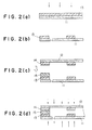
- the first layer 13 of an activation-energy-ray-hardening resin is firstly formed on the first substrate 11. This resin layer is then subjected to desired-pattern-wise exposure, for example, by using a pattern mask or by means of scanning exposure (Fig. 2(a)). The unexposed, unhardened area of the resin layer is removed by using, for example, a solvent to form a groove which will be an ink channel (This is a so called a developing process) (Fig. 2(b)). If necessary, a second layer of an activation-energy-ray-hardening resin (layer 15 in Fig. 2(b)) can be provided on the first layer 13 in the same way, and a groove can also be formed therein.
- the layer 15 can be formed by forming a layer of an activation-energy-ray-hardening resin on the layer 13 which has been hardened and developed, subjecting the layer to desired-pattern-wise exposure, and then removing unhardened area of the layer to form the layer 15. A groove which will finally be an ink channel is thus formed on the first substrate.
- the second substrate 12 is attached to the first substrate 11 which is provided with the groove for an ink channel. It is noted that the second substrate 12 may also be one having thereon a groove of a desired pattern provided by using an activation-energy-ray-hardening resin in the same manner as in the first substrate (Fig. 2(c)).
- the two substrates are attached to each other in the following manner.
- the two substrates are firstly faced each other as shown in Fig. 2(c).
- the attachment of the substrates may be conducted by using an adhesive agent. However, according to the preferred embodiment of the present invention, they are attached to each other without using any adhesive agent.
- the resin layer provided on the first substrate 11 (and the resin layer on the second substrate 12 if provided) is hardened to such a degree that the resin layer can have minimum hardness required to form a groove therein.
- the two substrates are then brought into close contact with each other with pressure, and heat and/or activation energy rays are applied thereto to further harden the resin.
- the two substrates can thus be firmly attached to each other.
- activation energy rays are to be applied from the outside of the first and/or second substrates (Fig. 2(d)).
- the activation energy rays are required to have high transmission like electron beams when the substrates are not transparent.
- the intensity of electron beams to be applied may be unlimited, when electron beams with very high intensity are applied, there is a possibility that the substrates are broken. It is therefore preferable to use an electron beam generator having an accelerating voltage of approximately 150 to 300 KeV.
- the method using no adhesive agent is very suitable for the production of excellent printing heads, because an adhesive agent may be clog an ink channel during the production process of printing heads.
- a printing head according to the present invention can be obtained by controlling the irradiation with activation energy rays so that the activation-energy-ray-hardening resin will finally be in the hardened state set forth below.
- the printing head comprises an ink channel connected to an ink-jetting nozzle, at least a part of the ink channel comprising an activation--energy-ray-hardening resin in the hardened state set forth below.
- the hardened state of the resin is such that the ratio (S) of the infrared spectral absorbance of an absorption peak observed between 1600 to 1650 cm -1 to the one observed between 1360 to 1400 cm -1 is in the range of 0.05 to 0.5, preferably 0.1 to 0.4.
- a printing head having an ink channel which comprises an activation-energy-ray-hardening resin having the value S, the ratio between the above two absorption peaks, in the range is extremely stable to an ink composition containing acetylene glycol or the like, which will be described later, and ensures good ink jet printing.
- the value Ef and Ei can be obtained, for example, in the following manner.
- an ethylenically unsaturated bond shows an absorption peak in the range of approximately 1600 to 1650 cm -1 .
- an activation-energy-ray-hardening resin there is a functional group which undergoes no change in its structure before and after hardening by exposure.
- An alkyl group which is an example of a functional group of this type shows an absorption peak in the range of approximately 1360 to 1400 cm -1 in the infrared spectrum.
- the values Ei and Ef can be respectively obtained by calculating the ratios of the absorbances of the ethylenically unsaturated bond in the resin before and after hardened to the absorbance of the absorption peak attributed to an alkyl group.
- a printing head having a value T in the above range ensures more excellent ink jet printing.
- a printing head comprises an ink channel connected to an ink-jetting nozzle, at least a part of the ink channel comprising an activation-energy-ray-hardening resin in the hardened state set forth below.
- the hardened state of the resin is such that the ratio (J) of the infrared spectral absorbance of an absorption peak observed between 900 and 920 cm -1 to the one observed between 1360 and 1400 cm -1 is in the range of 0.13 to 0.26, preferably 0.15 to 0.24.
- a printing head having an ink channel which comprises an activation-energy-ray-hardening resin having a value J, a ratio between the above two absorption peaks, in the range is extremely stable to an ink composition containing acetylene glycol or the like, which will be described later, and ensures good ink jet printing.
- the values Pf and Pi can be obtained, for example, in the following manner.
- an epoxy group shows an absorption peak in the range of approximately 900 to 920 cm -1 . Therefore, as in the case of the value T, the values Pi and Pf can be respectively obtained by calculating the ratios of the absorbances attributed to an epoxy group in the resin before and after hardened to the absorbance attributed to a functional group which undergoes no change in its structure before and after the resin is hardened by exposure.
- a printing head having a value K in the above range ensures more excellent ink jet printing.
- a printing head which fulfills the requirements in the first and second embodiments at the same time is preferred.
- a preferable printing head is one comprising a hardened resin whose S value is in the range of 0.05 to 0.5 and, at the same time, whose J value is in the range of 0.13 to 0.26.
- the sum total of the product of the density and the thickness of the substrate to which the electron beams are applied, and the product of the density and the thickness of the resin layer is preferably 1 kg ⁇ m/m 3 or less, more preferably 0.7 kg ⁇ m/m 3 or less.
- a printing head which fulfills such a condition can be efficiently hardened when electron beams are applied thereto.
- the sum total of the product of the density and the thickness of the first and second substrate, and the product of the density and the thickness of the resin layer is preferably 2.0 kg ⁇ m/m 3 or less, more preferably 1.4 kg ⁇ m/m 3 or less.
- thin portions 20 are provided so as not to impair the mechanical strength of the printing head. It is also preferable to substantially decrease the above sum total by providing such a thin portion 20.
- a printing head comprises an ink channel connected to an ink-jetting nozzle, at least a part of the ink channel comprising an activation-energy-ray-hardening resin in the hardened state set forth below.
- the hardened state of the resin is such that the hardened resin after immersed in a 1% acetylene glycol solution at a temperature of 70°C for 15 days shows a drop of 0.07 to 0.5 in the Vickers hardness against the one before subjected to the immersion.
- a printing head having an ink channel which comprises a resin in such a hardened state is extremely stable to an ink composition containing acetylene glycol or the like, which will be described later, and ensures good ink jet printing.
- the printing heads according to the present invention are extremely stable to ink compositions containing acetylene glycol or the like, of which use to conventional printing heads produced by using an activation-energy-ray-hardening resin has been difficult, and ensure good ink jet printing.
- Ink compositions containing acetylene glycol represented, for example, by the following formula can be mentioned as the ink compositions of which use to conventional printing heads has been limited: wherein R 1 , R 2 , R 3 and R 4 represent independently a lower alkyl group, preferably a C 1-6 alkyl group, more preferably a C 1-4 alkyl group, and the total number of n and m is from 0 to 30, preferably from 3 to 10.
- the resin in the printing head is dissolved or swollen, and, in addition, the resin layer is flaked off to damage the printing head. For this reason, it has been difficult to use the ink compositions of this type with conventional printing heads.
- the printing heads according to the present invention are extremely stable to the ink compositions, so that they can achieve good ink jet printing.
- the ink compositions which are so difficult to apply to the conventional printing heads include that containing as an organic solvent glycol-ether such as triethylene glycol monobutyl ether, diethylene glycol monobutyl ether, dipropylene glycol monobutyl ether, propylene glycol monomethyl ether or propylene glycol monobutyl ether.
- glycol-ether such as triethylene glycol monobutyl ether, diethylene glycol monobutyl ether, dipropylene glycol monobutyl ether, propylene glycol monomethyl ether or propylene glycol monobutyl ether.
- ink compositions containing the acetylene glycol, glycol ether or the like which can be applied to the printing heads according to the present invention.
- those ink compositions which contain 0.1 to 10% by weight, particularly 0.5 to 5% by weight of an organic solvent such as acetylene glycol are preferred.
- the printing heads according to the present invention have a wide range of application, and can achieve good ink jet printing along with various ink compositions containing a variety of colorants, an organic solvent and an additive.
- a dye or a pigment can be used as the colorant.
- a coloring dye, a direct dye or a reactive dye can be used as a dye; and carbon black or an organic pigment of various types can be used as a pigment.
- the amount of a colorant to be added is determined in consideration of, for example, the density of printed images. It is however preferable that the amount of a colorant be approximately 0.5 to 10% of the total weight of the ink composition.
- the printing heads according to the present invention ensure good ink jet printing to ink compositions prepared by using an organic solvent selected from alcohols having approximately 1 to 4 carbon atoms, such as methanol, ethanol and propanol, ketones and ethers.
- an organic solvent selected from alcohols having approximately 1 to 4 carbon atoms, such as methanol, ethanol and propanol, ketones and ethers.
- a wetting agent plays an important role in an ink composition for ink jet printing.
- the printing heads according to the present invention also ensure good ink jet printing to ink compositions containing a variety of wetting agents.
- the wetting agent include polyhydric alcohols such as glycerol, ethylene glycol, diethylene glycol, triethylene glycol and propylene glycol; nitrogen-containing compounds such as dimethylformamide, 1,3-dimethyl-2-imidazolidinone, 2-pyrrolidone and n-methyl-2-pyrrolidone; urea; and sugars.
- the printing heads according to the present invention also ensure good ink jet printing to ink compositions containing other additives such as a preservative, an antifungal agent, a chelating agent, a surface active agent.
- Printing heads according to the present invention were prepared in the following manner.
- An activation-energy-ray-hardening resin ("Ohdil PR-155" manufactured by Tokyo Ohka Kogyo Co., Ltd.) was coated onto the surface of a first substrate made of stainless steel, having a thickness of 100 ⁇ m.
- the resin layer was subjected to desired-pattern-wise exposure (wavelength: 365 nm, exposure dose: 90 mJ/cm 2 ) four times.
- the unhardened area of the resin layer was removed by using a solvent to form a groove which would be an ink channel.
- the thickness of the resin layer became 400 ⁇ m.
- a second substrate made of nickel, having a thickness of 30 ⁇ m was placed on and attached to this resin layer.
- This attachment was conducted in such a manner that the first substrate and the second substrate were brought into close contact with each other with the application of pressure 800 g/cm 3 and heat 150°C, and then electron beams were applied thereto from both the first substrate side and the second substrate side.
- pressure 800 g/cm 3 and heat 150°C the application of pressure 800 g/cm 3 and heat 150°C
- electron beams were applied thereto from both the first substrate side and the second substrate side.
- a sample film (size: 5 mm ⁇ 10 mm; thickness: 200 ⁇ m) was prepared from the same active-energy-ray-hardening resin as was used for preparing the above printing head, by making it into the same hardened state as in the above printing head.
- the sample was immersed in 1% acetylene glycol solution at 70°C for 15 days.
- the density of the first substrate, that of the second substrate, and that of the resin were approximately 7.9 ⁇ 10 3 kg/m 3 , approximately 8.85 kg/m 3 and 1000 kg/m 3 , respectively. Therefore, the sum total of the product of the density and the thickness of the first substrate, that of the second substrate, and that of the resin layer was 1.46 kg.m/m 3 .
- ink compositions having the following formulations were prepared.
- % means “% by weight”; and Acetylene glycols Nos. 1, 2, 5 and 6 are those having the structures which are given in the table shown previously.
- Ink Composition I Acid Red 289 3% Diethylene glycol 10% Glycerol 15% Acetylene glycol No. 1 1.5% Water q.s. to 100%
- Ink Composition II Direct Blue 199 4% Glycerol 20% Triethylene glycol 10% Ethanol 5% Acetylene glycol No. 5 2% Water q.s. to 100% Ink Composition III Direct Yellow 86 2% Glycerol 5% Urea 5% 2-Pyrrolidone 5% Acetylene glycol No. 1 1% Acetylene glycol No. 6 0.4% Water q.s.
- Ink Composition VIII Direct Blue 199 2% Diethylene glycol 15% Triethylene glycol monobutyl ether 10% Water q.s. to 100% Ink Composition IX Acid Red 289 2% Glycerol 10% Diethylene glycol monobutyl ether 10% Acetylene glycol No. 5 1% Water q.s. to 100% Ink Composition X Acid Yellow 23 2% 2-Pyrrolidone 10% Dipropylene glycol monobutyl ether 5% Water q.s. to 100%
- a sample film (size: 5 mm ⁇ 10 mm; thickness: 200 ⁇ m) was prepared from the same activation-energy-ray-hardening resin as was used for preparing the above-described printing head, by making it into the same hardened state as in the above printing head.
- This sample was immersed in the above ink composition at 70°C for 15 days.
- the Young's modulus values of the sample before and after immersed were measured by an apparatus "TMA-100" manufactured by Seiko Instruments Inc.
- the ratio of the Young's modulus of the sample after the immersion to the one before the immersion was evaluated in accordance with the following criteria:
- the above printing head was immersed in the above ink composition at a surrounding temperature of 70°C for 15 days. Thereafter, the printing head was visually observed as to whether the substrates or the resin layer was flaked off or not, and evaluated in accordance with the following criteria:
- the above printing head was mounted on a printer, and the ink composition was charged in it. After printing was once conducted, the printer filled with the ink composition was allowed to stand at a surrounding temperature of 50°C for one month. Thereafter, printing was restarted, and the printed images obtained were evaluated in accordance with the following standard. It is noted that the response frequency of the printing head was 7.2 kHz and/or 4 kHz while the printing was conducted.
Landscapes
- Engineering & Computer Science (AREA)
- Manufacturing & Machinery (AREA)
- Particle Formation And Scattering Control In Inkjet Printers (AREA)
Claims (13)
- Une tête d'impression pour une utilisation dans l'impression par jet d'encre, comprenant une buse pour l'éjection de l'encre et un canal pour l'encre relié à la buse pour l'injection de l'encre,
au moins une partie du canal pour l'encre comprenant une résine à durcissement par activation avec des rayons énergétiques,
la résine à durcissement par activation avec des rayons énergétiques étant dans un état de durcissement tel que le rapport (S) entre l'absorption spectrale infrarouge d'un pic d'absorption observé entre 1600 et 1650 cm-1 et de celui observé entre 1360 et 1400 cm-1 est compris dans la gamme de 0,05 à 0,5. - Une tête d'impression selon la revendication 1, ayant une valeur T comprise entre 3 ou plus et 40 ou moins, la valeur T étant définie par l'équation suivante:
- Une tête d'impression pour une utilisation dans l'impression par jet d'encre, comprenant une buse pour l'éjection de l'encre et un canal pour l'encre relié à la buse pour l'injection de l'encre,
au moins une partie du canal pour l'encre comprenant une résine à durcissement par activation avec des rayons énergétiques,
la résine à durcissement par activation avec des rayons énergétiques étant dans un état de durcissement tel que le rapport (J) entre l'absorption spectrale infrarouge d'un pic d'absorption observé entre 900 et 920 cm-1 et de celui observé entre 1360 et 1400 cm-1 est dans la gamme de 0,13 à 0,26. - Une tête d'impression selon la revendication 3, ayant une valeur K comprise entre 40 ou plus et 70 ou moins, la valeur K étant définie par l'équation suivante:
- Une tête d'impression pour une utilisation dans l'impression par jet d'encre, comprenant une buse pour l'éjection de l'encre et un canal pour l'encre relié à la buse pour l'injection de l'encre,
au moins une partie du canal pour l'encre comprenant une résine à durcissement par activation avec des rayons énergétiques,
la résine à durcissement par activation avec des rayons énergétiques étant dans un état de durcissement tel que le rapport (S) entre l'absorption spectrale infrarouge d'un pic d'absorption observé entre 1600 et 1650 cm-1 et de celui observé entre 1360 et 1400 cm-1 est dans la gamme de 0,05 à 0,5 et tel que le rapport (J) entre l'absorption spectrale infrarouge d'un pic d'absorption observé entre 900 et 920 cm-1 et de celui observé entre 1360 et 1400 cm-1 est compris dans la gamme de 0,13 à 0,26. - Une tête d'impression selon l'une quelconque des revendications 1 à 5, dans laquelle la résine à durcissement par activation avec des rayons énergétiques est dans un état de durcissement tel que la résine durcie après avoir été immergée dans une solution d'acétylèneglycol à 1 % à une température de 70°C pendant 15 jours présente une diminution du module de Young de 0,05 à 0,4 par rapport à celui de la résine durcie avant d'avoir été immergée.
- Une tête d'impression pour une utilisation dans l'impression par jet d'encre, comprenant une buse pour l'éjection de l'encre et un canal pour l'encre relié à la buse pour l'injection de l'encre,
au moins une partie du canal pour l'encre comprenant une résine à durcissement par activation avec des rayons énergétiques,
la résine à durcissement par activation avec des rayons énergétiques étant dans un état de durcissement tel que la résine durcie après avoir été immergée dans une solution d'acétylèneglycol à 1 % à une température de 70°C pendant 15 jours présente une diminution de la dureté Vickers de 0,07 à 0,5 par rapport à celle de la résine durcie avant d'avoir été immergée. - Une tête d'impression selon la revendication 7, ayant une valeur T comprise entre 3 ou plus et 40 ou moins, la valeur T étant définie par l'équation suivante:
- Une tête d'impression selon la revendication 7, ayant une valeur K comprise entre 40 ou plus et 70 ou moins, la valeur K étant définie par l'équation suivante:
- Un procédé pour produire une tête d'impression pour une utilisation dans l'impression par jet d'encre, qui est définie par l'une quelconque des revendications 1 à 9, comprenant les étapes qui consistentà placer une résine à durcissement par activation avec des rayons énergétiques sur un premier substrat,à irradier la résine avec des rayons énergétiques activateurs pour réaliser l'exposition désirée selon un modèle,à éliminer la surface non durcie de la résine afin de former une rainure, qui sera un canal pour l'encre,à placer un second substrat sur la résine disposée sur le premier substrat afin d'assembler une tête d'impression età irradier la tête d'impression avec des rayons énergétiques activateurs en une quantité telle que celle nécessaire pour amener la résine dans un état de durcissement, qui est défini par l'une quelconque des revendications 1 à 9.
- Un procédé selon la revendication 10, dans lequel les rayons énergétiques activateurs, avec lesquels on irradie après avoir placé le second substrat, sont des faisceaux d'électrons.
- Un procédé selon la revendication 11, dans lequel l'irradiation avec les rayons énergétiques activateurs est effectuée soit sur la face du premier substrat soit sur la face du second substrat et dans lequel la résine satisfait à l'équation suivante :d1 est la densité du substrat, sur lequel les rayons énergétiques activateurs sont appliqués,D1 est l'épaisseur du substrat, sur lequel les rayons énergétiques activateurs sont appliqués.d2 est la densité de la couche de résine etD2 est l'épaisseur de la couche de résine.
- Un procédé selon la revendication 11, dans lequel l'irradiation avec les rayons énergétiques activateurs est effectuée à la fois sur la face du premier substrat ou sur la face du second substrat et dans lequel la résine satisfait à l'équation suivante:d3 est la densité du premier substrat,D3 est l'épaisseur du premier substrat,d4 est la densité du second substrat.D4 est l'épaisseur du second substrat,d5 est la densité de la couche de résine etD5 est l'épaisseur de la couche de résine.
Applications Claiming Priority (6)
| Application Number | Priority Date | Filing Date | Title |
|---|---|---|---|
| JP110340/93 | 1993-05-12 | ||
| JP11034093 | 1993-05-12 | ||
| JP11033893 | 1993-05-12 | ||
| JP110338/93 | 1993-05-12 | ||
| JP9675194A JP3415260B2 (ja) | 1993-05-12 | 1994-05-10 | インクジェット記録ヘッド及びその製造法 |
| JP96751/94 | 1994-05-10 |
Publications (3)
| Publication Number | Publication Date |
|---|---|
| EP0624474A2 EP0624474A2 (fr) | 1994-11-17 |
| EP0624474A3 EP0624474A3 (fr) | 1995-11-08 |
| EP0624474B1 true EP0624474B1 (fr) | 1998-07-15 |
Family
ID=27308199
Family Applications (1)
| Application Number | Title | Priority Date | Filing Date |
|---|---|---|---|
| EP19940303424 Expired - Lifetime EP0624474B1 (fr) | 1993-05-12 | 1994-05-12 | Têtes d'impression utilisées dans l'impression par jet d'encre et méthode de fabrication |
Country Status (4)
| Country | Link |
|---|---|
| EP (1) | EP0624474B1 (fr) |
| JP (1) | JP3415260B2 (fr) |
| DE (1) | DE69411627T2 (fr) |
| SG (1) | SG48032A1 (fr) |
Families Citing this family (2)
| Publication number | Priority date | Publication date | Assignee | Title |
|---|---|---|---|---|
| JP3485514B2 (ja) * | 1996-04-11 | 2004-01-13 | シチズン時計株式会社 | インクジェットヘッド及びその製造方法 |
| CN112937145B (zh) * | 2019-12-10 | 2022-10-11 | 精工爱普生株式会社 | 喷墨记录方法及喷墨记录装置 |
Family Cites Families (5)
| Publication number | Priority date | Publication date | Assignee | Title |
|---|---|---|---|---|
| US4417251A (en) * | 1980-03-06 | 1983-11-22 | Canon Kabushiki Kaisha | Ink jet head |
| NZ215095A (en) * | 1985-02-12 | 1989-04-26 | Napp Systems Inc | Photosensitive resin compositions |
| JPH0615631B2 (ja) * | 1987-03-06 | 1994-03-02 | 東洋インキ製造株式会社 | プラスチツク用活性エネルギ−線硬化型被覆剤 |
| JP2697937B2 (ja) * | 1989-12-15 | 1998-01-19 | キヤノン株式会社 | 活性エネルギー線硬化性樹脂組成物 |
| JP2932877B2 (ja) * | 1992-02-06 | 1999-08-09 | セイコーエプソン株式会社 | インクジェットヘッドの製造方法 |
-
1994
- 1994-05-10 JP JP9675194A patent/JP3415260B2/ja not_active Expired - Fee Related
- 1994-05-12 SG SG1996006340A patent/SG48032A1/en unknown
- 1994-05-12 EP EP19940303424 patent/EP0624474B1/fr not_active Expired - Lifetime
- 1994-05-12 DE DE1994611627 patent/DE69411627T2/de not_active Expired - Fee Related
Also Published As
| Publication number | Publication date |
|---|---|
| DE69411627D1 (de) | 1998-08-20 |
| SG48032A1 (en) | 1998-04-17 |
| DE69411627T2 (de) | 1998-12-24 |
| JP3415260B2 (ja) | 2003-06-09 |
| EP0624474A2 (fr) | 1994-11-17 |
| JPH07137260A (ja) | 1995-05-30 |
| EP0624474A3 (fr) | 1995-11-08 |
Similar Documents
| Publication | Publication Date | Title |
|---|---|---|
| US7858670B2 (en) | Photosensitive inkjet ink | |
| US5738916A (en) | Ultraviolet-curing composition, pattern forming method making use of the same, printed-wiring board and its production | |
| EP1865345B1 (fr) | Composition d'encre pour jet d'encre pour un filtre coloré, procédé servant à produire un filtre coloré et filtre coloré | |
| JP2003192943A (ja) | インクジェット記録用インクとそれを用いたインクジェット記録方法及びインクジェット記録装置 | |
| JP2003292855A (ja) | インクジェット記録用インクおよび画像形成方法 | |
| US20090286001A1 (en) | Active-energy radiation-polymerizable substance, active-energy radiation-curable liquid composition, active-energy radiation-curable ink, ink jet recording method, ink cartridge, recording unit, and ink jet recording apparatus | |
| KR101367572B1 (ko) | 염료를 포함하는 고분자 화합물 및 이를 포함하는 경화성 수지 조성물 | |
| JP2000186243A (ja) | インク、高分子化合物膜の形成方法及び画像形成方法 | |
| JP2000336295A (ja) | 光硬化型インクジェット記録用インク組成物およびそれを用いたインクジェット記録方法 | |
| EP0624474B1 (fr) | Têtes d'impression utilisées dans l'impression par jet d'encre et méthode de fabrication | |
| JP2008266635A (ja) | 活性エネルギー線硬化型液体組成物及び液体カートリッジ | |
| JP2004009360A (ja) | 活性光線硬化型インクジェット記録方法 | |
| JP2004182875A (ja) | カチオン重合性光硬化インク用洗浄液及びインクジェットプリンタのクリーニング方法 | |
| JPH09208609A (ja) | 活性エネルギー線重合組成物、該組成物を用いた積層体及び印刷方法 | |
| JP5617228B2 (ja) | 紫外線硬化型インクジェット記録用インク組成物 | |
| JP6665136B2 (ja) | モノマー混合物、及びそれを含む硬化性組成物 | |
| JP2000038531A (ja) | インクジェットプリンタ用インキ | |
| JP2004029390A (ja) | 液体充填方法及び液晶表示素子 | |
| JP3342242B2 (ja) | 液晶用カラーフィルターおよびその製造方法ならびに液晶パネル | |
| JP2019163381A (ja) | インクジェット記録用インク、及び記録方法 | |
| JPH10104416A (ja) | カラーフィルター、これを用いた液晶素子、及びこれらの製造方法、該製造方法に用いられるインクジェット用インク | |
| JP2002302626A (ja) | 記録用インク、インクジェット記録方法、カラーフィルタの製造方法、液晶ディスプレイパネルの製造方法及び液晶ディスプレイパネル | |
| WO2024063144A1 (fr) | Composition durcissable pour impression à jet d'encre, composant électronique et procédé de production de composant électronique | |
| US20230032881A1 (en) | Active energy ray polymerization initiator, active energy ray curing composition, active energy ray curing ink, aqueous active energy ray curing ink, container, image forming device, image forming method, and method of manufacturing active energy ray polymerization initiator | |
| JP2004243761A (ja) | インクジェット記録方法 |
Legal Events
| Date | Code | Title | Description |
|---|---|---|---|
| PUAI | Public reference made under article 153(3) epc to a published international application that has entered the european phase |
Free format text: ORIGINAL CODE: 0009012 |
|
| AK | Designated contracting states |
Kind code of ref document: A2 Designated state(s): CH DE FR GB IT LI NL SE |
|
| PUAL | Search report despatched |
Free format text: ORIGINAL CODE: 0009013 |
|
| AK | Designated contracting states |
Kind code of ref document: A3 Designated state(s): CH DE FR GB IT LI NL SE |
|
| 17P | Request for examination filed |
Effective date: 19951201 |
|
| 17Q | First examination report despatched |
Effective date: 19970224 |
|
| GRAG | Despatch of communication of intention to grant |
Free format text: ORIGINAL CODE: EPIDOS AGRA |
|
| GRAG | Despatch of communication of intention to grant |
Free format text: ORIGINAL CODE: EPIDOS AGRA |
|
| GRAH | Despatch of communication of intention to grant a patent |
Free format text: ORIGINAL CODE: EPIDOS IGRA |
|
| GRAH | Despatch of communication of intention to grant a patent |
Free format text: ORIGINAL CODE: EPIDOS IGRA |
|
| GRAA | (expected) grant |
Free format text: ORIGINAL CODE: 0009210 |
|
| ITF | It: translation for a ep patent filed |
Owner name: BARZANO' E ZANARDO MILANO S.P.A. |
|
| AK | Designated contracting states |
Kind code of ref document: B1 Designated state(s): CH DE FR GB IT LI NL SE |
|
| REG | Reference to a national code |
Ref country code: CH Ref legal event code: NV Representative=s name: WILLIAM BLANC & CIE CONSEILS EN PROPRIETE INDUSTRI Ref country code: CH Ref legal event code: EP |
|
| REF | Corresponds to: |
Ref document number: 69411627 Country of ref document: DE Date of ref document: 19980820 |
|
| ET | Fr: translation filed | ||
| PLBE | No opposition filed within time limit |
Free format text: ORIGINAL CODE: 0009261 |
|
| STAA | Information on the status of an ep patent application or granted ep patent |
Free format text: STATUS: NO OPPOSITION FILED WITHIN TIME LIMIT |
|
| 26N | No opposition filed | ||
| REG | Reference to a national code |
Ref country code: GB Ref legal event code: IF02 |
|
| PGFP | Annual fee paid to national office [announced via postgrant information from national office to epo] |
Ref country code: DE Payment date: 20060508 Year of fee payment: 13 |
|
| PGFP | Annual fee paid to national office [announced via postgrant information from national office to epo] |
Ref country code: GB Payment date: 20060510 Year of fee payment: 13 |
|
| PGFP | Annual fee paid to national office [announced via postgrant information from national office to epo] |
Ref country code: FR Payment date: 20060515 Year of fee payment: 13 |
|
| GBPC | Gb: european patent ceased through non-payment of renewal fee |
Effective date: 20070512 |
|
| REG | Reference to a national code |
Ref country code: FR Ref legal event code: ST Effective date: 20080131 |
|
| PG25 | Lapsed in a contracting state [announced via postgrant information from national office to epo] |
Ref country code: DE Free format text: LAPSE BECAUSE OF NON-PAYMENT OF DUE FEES Effective date: 20071201 |
|
| PG25 | Lapsed in a contracting state [announced via postgrant information from national office to epo] |
Ref country code: GB Free format text: LAPSE BECAUSE OF NON-PAYMENT OF DUE FEES Effective date: 20070512 |
|
| PG25 | Lapsed in a contracting state [announced via postgrant information from national office to epo] |
Ref country code: FR Free format text: LAPSE BECAUSE OF NON-PAYMENT OF DUE FEES Effective date: 20070531 |
|
| REG | Reference to a national code |
Ref country code: CH Ref legal event code: PFA Owner name: SEIKO EPSON CORPORATION Free format text: SEIKO EPSON CORPORATION#4-1, NISHISHINJUKU 2-CHOME#SHINJUKU-KU TOKYO-TO (JP) -TRANSFER TO- SEIKO EPSON CORPORATION#4-1, NISHISHINJUKU 2-CHOME#SHINJUKU-KU TOKYO-TO (JP) |
|
| REG | Reference to a national code |
Ref country code: CH Ref legal event code: PCAR Free format text: NOVAGRAAF SWITZERLAND SA;CHEMIN DE L'ECHO 3;1213 ONEX (CH) |
|
| PGFP | Annual fee paid to national office [announced via postgrant information from national office to epo] |
Ref country code: SE Payment date: 20110512 Year of fee payment: 18 Ref country code: CH Payment date: 20110512 Year of fee payment: 18 |
|
| PGFP | Annual fee paid to national office [announced via postgrant information from national office to epo] |
Ref country code: NL Payment date: 20110520 Year of fee payment: 18 |
|
| PGFP | Annual fee paid to national office [announced via postgrant information from national office to epo] |
Ref country code: IT Payment date: 20110518 Year of fee payment: 18 |
|
| REG | Reference to a national code |
Ref country code: NL Ref legal event code: V1 Effective date: 20121201 |
|
| REG | Reference to a national code |
Ref country code: CH Ref legal event code: PL |
|
| REG | Reference to a national code |
Ref country code: SE Ref legal event code: EUG |
|
| PG25 | Lapsed in a contracting state [announced via postgrant information from national office to epo] |
Ref country code: LI Free format text: LAPSE BECAUSE OF NON-PAYMENT OF DUE FEES Effective date: 20120531 Ref country code: CH Free format text: LAPSE BECAUSE OF NON-PAYMENT OF DUE FEES Effective date: 20120531 |
|
| PG25 | Lapsed in a contracting state [announced via postgrant information from national office to epo] |
Ref country code: SE Free format text: LAPSE BECAUSE OF NON-PAYMENT OF DUE FEES Effective date: 20120513 Ref country code: IT Free format text: LAPSE BECAUSE OF NON-PAYMENT OF DUE FEES Effective date: 20120512 |
|
| PG25 | Lapsed in a contracting state [announced via postgrant information from national office to epo] |
Ref country code: NL Free format text: LAPSE BECAUSE OF NON-PAYMENT OF DUE FEES Effective date: 20121201 |