EP0624474B1 - Printing heads for use in ink jet printing and method for producing the same - Google Patents
Printing heads for use in ink jet printing and method for producing the same Download PDFInfo
- Publication number
- EP0624474B1 EP0624474B1 EP19940303424 EP94303424A EP0624474B1 EP 0624474 B1 EP0624474 B1 EP 0624474B1 EP 19940303424 EP19940303424 EP 19940303424 EP 94303424 A EP94303424 A EP 94303424A EP 0624474 B1 EP0624474 B1 EP 0624474B1
- Authority
- EP
- European Patent Office
- Prior art keywords
- resin
- ink
- activation
- hardened
- energy
- Prior art date
- Legal status (The legal status is an assumption and is not a legal conclusion. Google has not performed a legal analysis and makes no representation as to the accuracy of the status listed.)
- Expired - Lifetime
Links
- 238000007639 printing Methods 0.000 title claims description 81
- 238000007641 inkjet printing Methods 0.000 title claims description 44
- 238000004519 manufacturing process Methods 0.000 title claims description 9
- 229920005989 resin Polymers 0.000 claims description 121
- 239000011347 resin Substances 0.000 claims description 121
- 239000000758 substrate Substances 0.000 claims description 66
- -1 acetylene glycol Chemical compound 0.000 claims description 31
- LYCAIKOWRPUZTN-UHFFFAOYSA-N ethylene glycol Natural products OCCO LYCAIKOWRPUZTN-UHFFFAOYSA-N 0.000 claims description 29
- HSFWRNGVRCDJHI-UHFFFAOYSA-N alpha-acetylene Natural products C#C HSFWRNGVRCDJHI-UHFFFAOYSA-N 0.000 claims description 27
- WGCNASOHLSPBMP-UHFFFAOYSA-N hydroxyacetaldehyde Natural products OCC=O WGCNASOHLSPBMP-UHFFFAOYSA-N 0.000 claims description 26
- 230000004913 activation Effects 0.000 claims description 17
- 238000010521 absorption reaction Methods 0.000 claims description 14
- 238000000034 method Methods 0.000 claims description 14
- 238000002835 absorbance Methods 0.000 claims description 12
- 238000010894 electron beam technology Methods 0.000 claims description 12
- 125000003700 epoxy group Chemical group 0.000 claims description 10
- 230000003595 spectral effect Effects 0.000 claims description 8
- 230000001678 irradiating effect Effects 0.000 claims description 4
- 239000000976 ink Substances 0.000 description 81
- 239000000203 mixture Substances 0.000 description 45
- PEDCQBHIVMGVHV-UHFFFAOYSA-N Glycerine Chemical compound OCC(O)CO PEDCQBHIVMGVHV-UHFFFAOYSA-N 0.000 description 21
- MTHSVFCYNBDYFN-UHFFFAOYSA-N diethylene glycol Chemical compound OCCOCCO MTHSVFCYNBDYFN-UHFFFAOYSA-N 0.000 description 19
- XLYOFNOQVPJJNP-UHFFFAOYSA-N water Substances O XLYOFNOQVPJJNP-UHFFFAOYSA-N 0.000 description 10
- 238000011156 evaluation Methods 0.000 description 7
- LFQSCWFLJHTTHZ-UHFFFAOYSA-N Ethanol Chemical compound CCO LFQSCWFLJHTTHZ-UHFFFAOYSA-N 0.000 description 6
- 238000007654 immersion Methods 0.000 description 6
- 239000000853 adhesive Substances 0.000 description 5
- 125000000524 functional group Chemical group 0.000 description 5
- 239000000178 monomer Substances 0.000 description 5
- BDERNNFJNOPAEC-UHFFFAOYSA-N propan-1-ol Chemical compound CCCO BDERNNFJNOPAEC-UHFFFAOYSA-N 0.000 description 5
- PXHVJJICTQNCMI-UHFFFAOYSA-N Nickel Chemical compound [Ni] PXHVJJICTQNCMI-UHFFFAOYSA-N 0.000 description 4
- IISBACLAFKSPIT-UHFFFAOYSA-N bisphenol A Chemical compound C=1C=C(O)C=CC=1C(C)(C)C1=CC=C(O)C=C1 IISBACLAFKSPIT-UHFFFAOYSA-N 0.000 description 4
- 239000003086 colorant Substances 0.000 description 4
- 239000003960 organic solvent Substances 0.000 description 4
- HNJBEVLQSNELDL-UHFFFAOYSA-N pyrrolidin-2-one Chemical compound O=C1CCCN1 HNJBEVLQSNELDL-UHFFFAOYSA-N 0.000 description 4
- SMZOUWXMTYCWNB-UHFFFAOYSA-N 2-(2-methoxy-5-methylphenyl)ethanamine Chemical compound COC1=CC=C(C)C=C1CCN SMZOUWXMTYCWNB-UHFFFAOYSA-N 0.000 description 3
- NIXOWILDQLNWCW-UHFFFAOYSA-N 2-Propenoic acid Natural products OC(=O)C=C NIXOWILDQLNWCW-UHFFFAOYSA-N 0.000 description 3
- CERQOIWHTDAKMF-UHFFFAOYSA-N Methacrylic acid Chemical compound CC(=C)C(O)=O CERQOIWHTDAKMF-UHFFFAOYSA-N 0.000 description 3
- OKKJLVBELUTLKV-UHFFFAOYSA-N Methanol Chemical compound OC OKKJLVBELUTLKV-UHFFFAOYSA-N 0.000 description 3
- ZMXDDKWLCZADIW-UHFFFAOYSA-N N,N-Dimethylformamide Chemical compound CN(C)C=O ZMXDDKWLCZADIW-UHFFFAOYSA-N 0.000 description 3
- DNIAPMSPPWPWGF-UHFFFAOYSA-N Propylene glycol Chemical compound CC(O)CO DNIAPMSPPWPWGF-UHFFFAOYSA-N 0.000 description 3
- 125000000217 alkyl group Chemical group 0.000 description 3
- 235000019241 carbon black Nutrition 0.000 description 3
- 230000000052 comparative effect Effects 0.000 description 3
- 239000000975 dye Substances 0.000 description 3
- 238000009472 formulation Methods 0.000 description 3
- 238000002329 infrared spectrum Methods 0.000 description 3
- 238000006116 polymerization reaction Methods 0.000 description 3
- 239000000080 wetting agent Substances 0.000 description 3
- DNIAPMSPPWPWGF-VKHMYHEASA-N (+)-propylene glycol Chemical compound C[C@H](O)CO DNIAPMSPPWPWGF-VKHMYHEASA-N 0.000 description 2
- YPFDHNVEDLHUCE-UHFFFAOYSA-N 1,3-propanediol Substances OCCCO YPFDHNVEDLHUCE-UHFFFAOYSA-N 0.000 description 2
- 229940035437 1,3-propanediol Drugs 0.000 description 2
- CUVLMZNMSPJDON-UHFFFAOYSA-N 1-(1-butoxypropan-2-yloxy)propan-2-ol Chemical compound CCCCOCC(C)OCC(C)O CUVLMZNMSPJDON-UHFFFAOYSA-N 0.000 description 2
- IUVCFHHAEHNCFT-INIZCTEOSA-N 2-[(1s)-1-[4-amino-3-(3-fluoro-4-propan-2-yloxyphenyl)pyrazolo[3,4-d]pyrimidin-1-yl]ethyl]-6-fluoro-3-(3-fluorophenyl)chromen-4-one Chemical compound C1=C(F)C(OC(C)C)=CC=C1C(C1=C(N)N=CN=C11)=NN1[C@@H](C)C1=C(C=2C=C(F)C=CC=2)C(=O)C2=CC(F)=CC=C2O1 IUVCFHHAEHNCFT-INIZCTEOSA-N 0.000 description 2
- COBPKKZHLDDMTB-UHFFFAOYSA-N 2-[2-(2-butoxyethoxy)ethoxy]ethanol Chemical compound CCCCOCCOCCOCCO COBPKKZHLDDMTB-UHFFFAOYSA-N 0.000 description 2
- RTZKZFJDLAIYFH-UHFFFAOYSA-N Diethyl ether Chemical compound CCOCC RTZKZFJDLAIYFH-UHFFFAOYSA-N 0.000 description 2
- SECXISVLQFMRJM-UHFFFAOYSA-N N-Methylpyrrolidone Chemical compound CN1CCCC1=O SECXISVLQFMRJM-UHFFFAOYSA-N 0.000 description 2
- XSQUKJJJFZCRTK-UHFFFAOYSA-N Urea Chemical compound NC(N)=O XSQUKJJJFZCRTK-UHFFFAOYSA-N 0.000 description 2
- 239000000654 additive Substances 0.000 description 2
- PXKLMJQFEQBVLD-UHFFFAOYSA-N bisphenol F Chemical compound C1=CC(O)=CC=C1CC1=CC=C(O)C=C1 PXKLMJQFEQBVLD-UHFFFAOYSA-N 0.000 description 2
- 239000004202 carbamide Substances 0.000 description 2
- 229940028356 diethylene glycol monobutyl ether Drugs 0.000 description 2
- 239000011521 glass Substances 0.000 description 2
- 239000002184 metal Substances 0.000 description 2
- 229910052751 metal Inorganic materials 0.000 description 2
- 229910052759 nickel Inorganic materials 0.000 description 2
- JCGNDDUYTRNOFT-UHFFFAOYSA-N oxolane-2,4-dione Chemical compound O=C1COC(=O)C1 JCGNDDUYTRNOFT-UHFFFAOYSA-N 0.000 description 2
- 239000000049 pigment Substances 0.000 description 2
- 229920000166 polytrimethylene carbonate Polymers 0.000 description 2
- 239000011342 resin composition Substances 0.000 description 2
- 239000002904 solvent Substances 0.000 description 2
- 229910001220 stainless steel Inorganic materials 0.000 description 2
- 239000010935 stainless steel Substances 0.000 description 2
- ZIBGPFATKBEMQZ-UHFFFAOYSA-N triethylene glycol Chemical compound OCCOCCOCCO ZIBGPFATKBEMQZ-UHFFFAOYSA-N 0.000 description 2
- 125000004178 (C1-C4) alkyl group Chemical group 0.000 description 1
- 125000004169 (C1-C6) alkyl group Chemical group 0.000 description 1
- 229920002818 (Hydroxyethyl)methacrylate Polymers 0.000 description 1
- LYCAIKOWRPUZTN-NMQOAUCRSA-N 1,2-dideuteriooxyethane Chemical compound [2H]OCCO[2H] LYCAIKOWRPUZTN-NMQOAUCRSA-N 0.000 description 1
- CYSGHNMQYZDMIA-UHFFFAOYSA-N 1,3-Dimethyl-2-imidazolidinon Chemical compound CN1CCN(C)C1=O CYSGHNMQYZDMIA-UHFFFAOYSA-N 0.000 description 1
- RWNUSVWFHDHRCJ-UHFFFAOYSA-N 1-butoxypropan-2-ol Chemical compound CCCCOCC(C)O RWNUSVWFHDHRCJ-UHFFFAOYSA-N 0.000 description 1
- ARXJGSRGQADJSQ-UHFFFAOYSA-N 1-methoxypropan-2-ol Chemical compound COCC(C)O ARXJGSRGQADJSQ-UHFFFAOYSA-N 0.000 description 1
- SYEWHONLFGZGLK-UHFFFAOYSA-N 2-[1,3-bis(oxiran-2-ylmethoxy)propan-2-yloxymethyl]oxirane Chemical compound C1OC1COCC(OCC1OC1)COCC1CO1 SYEWHONLFGZGLK-UHFFFAOYSA-N 0.000 description 1
- OMIGHNLMNHATMP-UHFFFAOYSA-N 2-hydroxyethyl prop-2-enoate Chemical compound OCCOC(=O)C=C OMIGHNLMNHATMP-UHFFFAOYSA-N 0.000 description 1
- GNSFRPWPOGYVLO-UHFFFAOYSA-N 3-hydroxypropyl 2-methylprop-2-enoate Chemical compound CC(=C)C(=O)OCCCO GNSFRPWPOGYVLO-UHFFFAOYSA-N 0.000 description 1
- QZPSOSOOLFHYRR-UHFFFAOYSA-N 3-hydroxypropyl prop-2-enoate Chemical compound OCCCOC(=O)C=C QZPSOSOOLFHYRR-UHFFFAOYSA-N 0.000 description 1
- YTNUOGWCFLMGLF-UHFFFAOYSA-N 5-methylbenzene-1,2,3,4-tetrol Chemical compound CC1=CC(O)=C(O)C(O)=C1O YTNUOGWCFLMGLF-UHFFFAOYSA-N 0.000 description 1
- KYARBIJYVGJZLB-UHFFFAOYSA-N 7-amino-4-hydroxy-2-naphthalenesulfonic acid Chemical compound OC1=CC(S(O)(=O)=O)=CC2=CC(N)=CC=C21 KYARBIJYVGJZLB-UHFFFAOYSA-N 0.000 description 1
- JMIFGARJSWXZSH-UHFFFAOYSA-N DMH1 Chemical compound C1=CC(OC(C)C)=CC=C1C1=CN2N=CC(C=3C4=CC=CC=C4N=CC=3)=C2N=C1 JMIFGARJSWXZSH-UHFFFAOYSA-N 0.000 description 1
- WPYCRFCQABTEKC-UHFFFAOYSA-N Diglycidyl resorcinol ether Chemical compound C1OC1COC(C=1)=CC=CC=1OCC1CO1 WPYCRFCQABTEKC-UHFFFAOYSA-N 0.000 description 1
- WOBHKFSMXKNTIM-UHFFFAOYSA-N Hydroxyethyl methacrylate Chemical compound CC(=C)C(=O)OCCO WOBHKFSMXKNTIM-UHFFFAOYSA-N 0.000 description 1
- 239000002202 Polyethylene glycol Substances 0.000 description 1
- 239000002253 acid Substances 0.000 description 1
- 230000000996 additive effect Effects 0.000 description 1
- 150000001298 alcohols Chemical class 0.000 description 1
- 125000002723 alicyclic group Chemical group 0.000 description 1
- 239000003429 antifungal agent Substances 0.000 description 1
- 229940121375 antifungal agent Drugs 0.000 description 1
- 230000005540 biological transmission Effects 0.000 description 1
- 125000004432 carbon atom Chemical group C* 0.000 description 1
- 239000006229 carbon black Substances 0.000 description 1
- 125000003178 carboxy group Chemical group [H]OC(*)=O 0.000 description 1
- 239000002738 chelating agent Substances 0.000 description 1
- 238000004040 coloring Methods 0.000 description 1
- 238000005520 cutting process Methods 0.000 description 1
- 239000000982 direct dye Substances 0.000 description 1
- DHQJMKJYFOHOSY-UHFFFAOYSA-L disodium 4-amino-3-[[4-[4-[(2,4-diaminophenyl)diazenyl]-3-methylphenyl]-2-methylphenyl]diazenyl]-5-oxido-6-phenyldiazenyl-7-sulfonaphthalene-2-sulfonate Chemical compound [Na+].[Na+].Cc1cc(ccc1N=Nc1ccc(N)cc1N)-c1ccc(N=Nc2c(N)c3c(O)c(N=Nc4ccccc4)c(cc3cc2S([O-])(=O)=O)S([O-])(=O)=O)c(C)c1 DHQJMKJYFOHOSY-UHFFFAOYSA-L 0.000 description 1
- 239000003822 epoxy resin Substances 0.000 description 1
- 238000005530 etching Methods 0.000 description 1
- 150000002170 ethers Chemical class 0.000 description 1
- 125000003055 glycidyl group Chemical group C(C1CO1)* 0.000 description 1
- VOZRXNHHFUQHIL-UHFFFAOYSA-N glycidyl methacrylate Chemical compound CC(=C)C(=O)OCC1CO1 VOZRXNHHFUQHIL-UHFFFAOYSA-N 0.000 description 1
- LNEPOXFFQSENCJ-UHFFFAOYSA-N haloperidol Chemical compound C1CC(O)(C=2C=CC(Cl)=CC=2)CCN1CCCC(=O)C1=CC=C(F)C=C1 LNEPOXFFQSENCJ-UHFFFAOYSA-N 0.000 description 1
- 150000002576 ketones Chemical class 0.000 description 1
- 239000007788 liquid Substances 0.000 description 1
- QJGQUHMNIGDVPM-UHFFFAOYSA-N nitrogen group Chemical group [N] QJGQUHMNIGDVPM-UHFFFAOYSA-N 0.000 description 1
- 229920003986 novolac Polymers 0.000 description 1
- 239000012860 organic pigment Substances 0.000 description 1
- RPQRDASANLAFCM-UHFFFAOYSA-N oxiran-2-ylmethyl prop-2-enoate Chemical compound C=CC(=O)OCC1CO1 RPQRDASANLAFCM-UHFFFAOYSA-N 0.000 description 1
- 229920000647 polyepoxide Polymers 0.000 description 1
- 229920001223 polyethylene glycol Polymers 0.000 description 1
- 229920001451 polypropylene glycol Polymers 0.000 description 1
- 239000003755 preservative agent Substances 0.000 description 1
- 230000002335 preservative effect Effects 0.000 description 1
- 239000000985 reactive dye Substances 0.000 description 1
- 235000000346 sugar Nutrition 0.000 description 1
- 150000005846 sugar alcohols Polymers 0.000 description 1
- 150000008163 sugars Chemical class 0.000 description 1
- 239000004094 surface-active agent Substances 0.000 description 1
- 230000008961 swelling Effects 0.000 description 1
- UJMBCXLDXJUMFB-GLCFPVLVSA-K tartrazine Chemical compound [Na+].[Na+].[Na+].[O-]C(=O)C1=NN(C=2C=CC(=CC=2)S([O-])(=O)=O)C(=O)C1\N=N\C1=CC=C(S([O-])(=O)=O)C=C1 UJMBCXLDXJUMFB-GLCFPVLVSA-K 0.000 description 1
- 235000012756 tartrazine Nutrition 0.000 description 1
- 239000004149 tartrazine Substances 0.000 description 1
Images

Classifications
-
- B—PERFORMING OPERATIONS; TRANSPORTING
- B41—PRINTING; LINING MACHINES; TYPEWRITERS; STAMPS
- B41J—TYPEWRITERS; SELECTIVE PRINTING MECHANISMS, i.e. MECHANISMS PRINTING OTHERWISE THAN FROM A FORME; CORRECTION OF TYPOGRAPHICAL ERRORS
- B41J2/00—Typewriters or selective printing mechanisms characterised by the printing or marking process for which they are designed
- B41J2/005—Typewriters or selective printing mechanisms characterised by the printing or marking process for which they are designed characterised by bringing liquid or particles selectively into contact with a printing material
- B41J2/01—Ink jet
- B41J2/135—Nozzles
- B41J2/16—Production of nozzles
- B41J2/1621—Manufacturing processes
- B41J2/1631—Manufacturing processes photolithography
-
- B—PERFORMING OPERATIONS; TRANSPORTING
- B41—PRINTING; LINING MACHINES; TYPEWRITERS; STAMPS
- B41J—TYPEWRITERS; SELECTIVE PRINTING MECHANISMS, i.e. MECHANISMS PRINTING OTHERWISE THAN FROM A FORME; CORRECTION OF TYPOGRAPHICAL ERRORS
- B41J2/00—Typewriters or selective printing mechanisms characterised by the printing or marking process for which they are designed
- B41J2/005—Typewriters or selective printing mechanisms characterised by the printing or marking process for which they are designed characterised by bringing liquid or particles selectively into contact with a printing material
- B41J2/01—Ink jet
- B41J2/135—Nozzles
- B41J2/16—Production of nozzles
- B41J2/1607—Production of print heads with piezoelectric elements
- B41J2/1612—Production of print heads with piezoelectric elements of stacked structure type, deformed by compression/extension and disposed on a diaphragm
-
- B—PERFORMING OPERATIONS; TRANSPORTING
- B41—PRINTING; LINING MACHINES; TYPEWRITERS; STAMPS
- B41J—TYPEWRITERS; SELECTIVE PRINTING MECHANISMS, i.e. MECHANISMS PRINTING OTHERWISE THAN FROM A FORME; CORRECTION OF TYPOGRAPHICAL ERRORS
- B41J2/00—Typewriters or selective printing mechanisms characterised by the printing or marking process for which they are designed
- B41J2/005—Typewriters or selective printing mechanisms characterised by the printing or marking process for which they are designed characterised by bringing liquid or particles selectively into contact with a printing material
- B41J2/01—Ink jet
- B41J2/135—Nozzles
- B41J2/16—Production of nozzles
- B41J2/1621—Manufacturing processes
- B41J2/1623—Manufacturing processes bonding and adhesion
-
- B—PERFORMING OPERATIONS; TRANSPORTING
- B41—PRINTING; LINING MACHINES; TYPEWRITERS; STAMPS
- B41J—TYPEWRITERS; SELECTIVE PRINTING MECHANISMS, i.e. MECHANISMS PRINTING OTHERWISE THAN FROM A FORME; CORRECTION OF TYPOGRAPHICAL ERRORS
- B41J2/00—Typewriters or selective printing mechanisms characterised by the printing or marking process for which they are designed
- B41J2/005—Typewriters or selective printing mechanisms characterised by the printing or marking process for which they are designed characterised by bringing liquid or particles selectively into contact with a printing material
- B41J2/01—Ink jet
- B41J2/135—Nozzles
- B41J2/14—Structure thereof only for on-demand ink jet heads
- B41J2002/14387—Front shooter
Description
at least a part of the ink channel comprising an activation-energy-ray-hardening resin,
the activation-energy-ray-hardening resin being in such a hardened state that the ratio (S) of the infrared spectral absorbance of an absorption peak observed between 1600 and 1650 cm-1 to the one observed between 1360 and 1400 cm-1 is in the range of 0.05 to 0.5.
at least a part of the ink channel comprising an activation-energy-ray-hardening resin,
the activation-energy-ray-hardening resin being in such a hardened state that the ratio (J) of the infrared spectral absorbance of an absorption peak observed between 900 and 920 cm-1 to the one observed between 1360 and 1400 cm-1 is in the range of 0.13 to 0.26.
at least a part of the ink channel comprising an activation-energy-ray-hardening resin,
the activation-energy-ray-hardening resin being in such a hardened state that the hardened resin after being immersed in a 1% acetylene glycol solution at a temperature of 70°C for 15 days shows a drop of 0.07 to 0.5 in the Vickers Hardness against the one before being subjected to the immersion.

| R1 | R2 | R3 | R4 | n+m | ||
| No. 1 | iso-butyl | methyl | methyl | iso- | 10 | |
| No. 2 | iso-butyl | methyl | methyl | iso-butyl | 3.5 | |
| No. 3 | ethyl | | methyl | ethyl | 10 | |
| No. 4 | methyl | methyl | methyl | methyl | 0 | |
| No. 5 | ethyl | methyl | methyl | ethyl | 0 | |
| No. 6 | iso-butyl | methyl | methyl | iso-butyl | 0 |
| S | T | Drop in Vickers hardness | Drop in Young's modulus | ||
| Example | A1 | 0.47 | 38 | 0.48 | 0.38 |
| A2 | 0.42 | 34 | 0.33 | 0.32 | |
| A3 | 0.39 | 28 | 0.32 | 0.19 | |
| A4 | 0.31 | 19 | 0.21 | 0.10 | |
| A5 | 0.18 | 10 | 0.18 | 0.08 | |
| A6 | 0.11 | 5 | 0.11 | 0.06 | |
| A7 | 0.07 | 7 | 0.38 | 0.28 | |
| A8 | 0.25 | 25 | 0.11 | 0.08 | |
| A9 | 0.09 | 12 | 0.19 | 0.25 | |
| A10 | 0.41 | 31 | 0.44 | 0.33 | |
| A11 | 0.06 | 5 | 0.08 | 0.09 | |
| A12 | 0.18 | 11 | 0.20 | 0.12 | |
| A13 | 0.32 | 24 | 0.25 | 0.18 | |
| A14 | 0.48 | 35 | 0.45 | 0.35 | |
| Comparative Example | A1 | 0.04 | 2 | 0.08 | 0.04 |
| A2 | 0.53 | 45 | 0.65 | 0.55 | |
| A3 | 0.62 | 52 | 0.69 | 0.49 | |
| A4 | 0.65 | 60 | 0.80 | 0.70 | |
| A5 | 0.03 | 2 | 0.05 | 0.02 | |
| A6 | 0.55 | 42 | 0.63 | 0.52 |
| J | K | Drop in Vickers hardness | Drop in Young's modulus | ||
| Example | B1 | 0.14 | 48 | 0.24 | 0.15 |
| B2 | 0.17 | 55 | 0.30 | 0.18 | |
| B3 | 0.17 | 75 | 0.35 | 0.21 | |
| B4 | 0.2 | 66 | 0.41 | 0.17 | |
| B5 | 0.2 | 30 | 0.28 | 0.14 | |
| B6 | 0.22 | 56 | 0.31 | 0.25 | |
| B7 | 0.23 | 73 | 0.44 | 0.35 | |
| B8 | 0.24 | 45 | 0.25 | 0.16 | |
| B9 | 0.24 | 52 | 0.32 | 0.18 | |
| B10 | 0.25 | 60 | 0.48 | 0.33 | |
| Comparative Example | B1 | 0.05 | 55 | 0.03 | 0.02 |
| B2 | 0.12 | 32 | 0.06 | 0.04 | |
| B3 | 0.28 | 45 | 0.55 | 0.45 | |
| B4 | 0.33 | 82 | 0.65 | 0.70 |
| S | J | Drop in Vickers hardness | Drop in Young's modulus | ||
| Example | C1 | 0.09 | 0.16 | 0.21 | 0.13 |
| C2 | 0.33 | 0.21 | 0.18 | 0.08 | |
| C3 | 0.24 | 0.18 | 0.15 | 0.06 | |
| C4 | 0.47 | 0.14 | 0.29 | 0.18 | |
| C5 | 0.11 | 0.25 | 0.21 | 0.12 | |
| C6 | 0.07 | 0.22 | 0.26 | 0.15 | |
| C7 | 0.29 | 0.13 | 0.27 | 0.16 | |
| C8 | 0.42 | 0.17 | 0.20 | 0.12 | |
| C9 | 0.19 | 0.15 | 0.10 | 0.05 | |
| C10 | 0.39 | 0.20 | 0.24 | 0.10 | |
| Comparative Example | C1 | 0.73 | 0.09 | 0.55 | 0.45 |
| C2 | 0.02 | 0.34 | 0.53 | 0.44 | |
| C3 | 0.61 | 0.31 | 0.88 | 0.80 |
| Ink Composition I | |
| Acid Red 289 | 3% |
| Diethylene glycol | 10% |
| Glycerol | 15% |
| Acetylene glycol No. 1 | 1.5% |
| Water | q.s. to 100% |
| Ink Composition II | |
| Direct Blue 199 | 4% |
| Glycerol | 20% |
| Triethylene glycol | 10% |
| Ethanol | 5% |
| Acetylene glycol No. 5 | 2% |
| Water | q.s. to 100% |
| Ink Composition III | |
| Direct Yellow 86 | 2% |
| Glycerol | 5% |
| Urea | 5% |
| 2-Pyrrolidone | 5% |
| Acetylene glycol No. 1 | 1% |
| Acetylene glycol No. 6 | 0.4% |
| Water | q.s. to 100% |
| Ink Composition IV | |
| Food Black 2 | 4% |
| Diethylene glycol | 10% |
| 1,3-Propane diol | 4% |
| n-Propanol | 4% |
| Acetylene glycol No. 1 | 2% |
| Acetylene glycol No. 2 | 2% |
| Water | q.s. to 100% |
| Ink Composition V | |
| Direct Black 154 | 4% |
| Glycerol | 4% |
| Ethylene glycol | 2% |
| Ethanol | 5% |
| Water | q.s. to 100% |
| Ink Composition VI | |
| Direct Yellow 86 | 2% |
| Glycerol | 3% |
| 2-Pyrrolidone | 3% |
| Water | q.s. to 100% |
| Ink Composition VII | |
| Food Black 2 | 4% |
| Diethylene glycol | 10% |
| 1,3-Propane diol | 5% |
| n-Propanol | 4% |
| Water | q.s. to 100% |
| Ink Composition VIII | |
| Direct Blue 199 | 2% |
| Diethylene glycol | 15% |
| Triethylene glycol monobutyl ether | 10% |
| Water | q.s. to 100% |
| Ink Composition IX | |
| Acid Red 289 | 2% |
| Glycerol | 10% |
| Diethylene glycol monobutyl ether | 10% |
| Acetylene glycol No. 5 | 1% |
| Water | q.s. to 100% |
| Ink Composition X | |
| Acid Yellow 23 | 2% |
| 2-Pyrrolidone | 10% |
| Dipropylene glycol monobutyl ether | 5% |
| Water | q.s. to 100% |


Claims (13)
- A printing head for use in ink jet printing, comprising an ink-jetting nozzle and an ink channel connected to the ink-jetting nozzle,
at least a part of the ink channel comprising an activation-energy-ray-hardening resin,
the activation-energy-ray-hardening resin being in such a hardened state that the ratio (S) of the infrared spectral absorbance of an absorption peak observed between 1600 and 1650 cm-1 to the one observed between 1360 and 1400 cm-1 is in the range of 0.05 to 0.5. - A printing head according to Claim 1, having a value T of 3 or more and 40 or less, the value T being defined by the following equation:
- A printing head for use in ink jet printing, comprising an ink-jetting nozzle and an ink channel connected to the ink-jetting nozzle,
at least a part of the ink channel comprising an activation-energy-ray-hardening resin,
the activation-energy-ray-hardening resin being in such a hardened state that the ratio (J) of the infrared spectral absorbance of an absorption peak observed between 900 and 920 cm-1 to the one observed between 1360 and 1400 cm-1 is in the range of 0.13 to 0.26. - A printing head according to Claim 3, having a value K of 40 or more and 70 or less, the value K being defined by the following equation:
- A printing head for use in ink jet printing, comprising an ink-jetting nozzle and an ink channel connected to the ink-jetting nozzle,
at least a part of the ink channel comprising an activation-energy-ray-hardening resin,
the activation-energy-ray-hardening resin being in such a hardened state that the ratio (S) of the infrared spectral absorbance of an absorption peak observed between 1600 and 1650 cm-1 to the one observed between 1360 and 1400 cm-1 is in the range of 0.05 to 0.5, and that the ratio (J) of the infrared spectral absorbance of an absorption peak observed between 900 and 920 cm-1 to the one observed between 1360 and 1400 cm-1 is in the range of 0.13 to 0.26. - A printing head according to any one of Claims 1 to 5, wherein the activation-energy-ray-hardening resin is in such a hardened state that the hardened resin after being immersed in 1% acetylene glycol solution at 70°C for 15 days shows a drop of 0.05 to 0.4 in the Young's modulus against that of the hardened resin before being immersed.
- A printing head for use in ink jet printing, comprising an ink-jetting nozzle and an ink channel connected to the ink-jetting nozzle,
at least a part of the ink channel comprising an activation-energy-ray-hardening resin,
the activation-energy-ray-hardening resin being in such a hardened state that the hardened resin after being immersed in 1% acetylene glycol solution at 70°C for 15 days shows a drop of 0.07 to 0.5 in the Vickers hardness against that of the hardened resin before being immersed. - A printing head according to Claim 7, having a value T of 3 or more and 40 or less, the value T being defined by the following equation:
- A printing head according to Claim 7, having a value K of 40 or more and 70 or less, the value K being defined by the following equation:
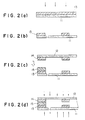
- A method for producing a printing head for use in ink jet printing which is defined by any one of Claims 1 to 9, comprising the steps of:placing an activation-energy-ray-hardening resin on a first substrate,irradiating the resin with activation energy rays to conduct desired-pattern-wise exposure,removing the unhardened area of the resin to form a groove which will be an ink channel,placing a second substrate on the resin provided on the first substrate to assemble a printing head, andirradiating the printing head with activation energy rays in such an amount as is required to make the resin into a hardened state which is defined by any one of Claims 1 to 9.
- A method according to Claim 10, wherein the activation energy rays irradiated with after the second substrate is placed are electron beams.
- A method according to claim 11, wherein the irradiation with activation energy ray is conducted from either the first substrate side or the second substrate side, and wherein the resin satisfies the following equation:d1 is the density of the substrate to which the activation energy rays are applied.D1 is the thickness of the substrate to which the activation energy rays are applied,d2 is the density of the resin layer, andD2 is the thickness of the resin layer.
- A method according to claim 11, wherein the irradiation with activation energy ray is conducted from both the first substrate side or the second substrate side, and wherein the resin satisfies the following equation:d3 is the density of the first substrate,D3 is the thickness of the first substrate,d4 is the density of the second substrate,D4 is the thickness of the second substrate,d5 is the density of the resin layer, andD5 is the thickness of the resin layer.
Applications Claiming Priority (6)
| Application Number | Priority Date | Filing Date | Title |
|---|---|---|---|
| JP11033893 | 1993-05-12 | ||
| JP11034093 | 1993-05-12 | ||
| JP110338/93 | 1993-05-12 | ||
| JP110340/93 | 1993-05-12 | ||
| JP9675194A JP3415260B2 (en) | 1993-05-12 | 1994-05-10 | Ink jet recording head and method of manufacturing the same |
| JP96751/94 | 1994-05-10 |
Publications (3)
| Publication Number | Publication Date |
|---|---|
| EP0624474A2 EP0624474A2 (en) | 1994-11-17 |
| EP0624474A3 EP0624474A3 (en) | 1995-11-08 |
| EP0624474B1 true EP0624474B1 (en) | 1998-07-15 |
Family
ID=27308199
Family Applications (1)
| Application Number | Title | Priority Date | Filing Date |
|---|---|---|---|
| EP19940303424 Expired - Lifetime EP0624474B1 (en) | 1993-05-12 | 1994-05-12 | Printing heads for use in ink jet printing and method for producing the same |
Country Status (4)
| Country | Link |
|---|---|
| EP (1) | EP0624474B1 (en) |
| JP (1) | JP3415260B2 (en) |
| DE (1) | DE69411627T2 (en) |
| SG (1) | SG48032A1 (en) |
Families Citing this family (2)
| Publication number | Priority date | Publication date | Assignee | Title |
|---|---|---|---|---|
| JP3485514B2 (en) * | 1996-04-11 | 2004-01-13 | シチズン時計株式会社 | Ink jet head and method of manufacturing the same |
| CN112937145B (en) * | 2019-12-10 | 2022-10-11 | 精工爱普生株式会社 | Ink jet recording method and ink jet recording apparatus |
Family Cites Families (5)
| Publication number | Priority date | Publication date | Assignee | Title |
|---|---|---|---|---|
| US4417251A (en) * | 1980-03-06 | 1983-11-22 | Canon Kabushiki Kaisha | Ink jet head |
| GB2171107B (en) * | 1985-02-12 | 1989-08-02 | Napp Systems Inc | Photosensitive resin composition |
| JPH0615631B2 (en) * | 1987-03-06 | 1994-03-02 | 東洋インキ製造株式会社 | Active energy ray-curable coating agent for plastics |
| JP2697937B2 (en) * | 1989-12-15 | 1998-01-19 | キヤノン株式会社 | Active energy ray-curable resin composition |
| JP2932877B2 (en) * | 1992-02-06 | 1999-08-09 | セイコーエプソン株式会社 | Method of manufacturing inkjet head |
-
1994
- 1994-05-10 JP JP9675194A patent/JP3415260B2/en not_active Expired - Fee Related
- 1994-05-12 DE DE1994611627 patent/DE69411627T2/en not_active Expired - Fee Related
- 1994-05-12 EP EP19940303424 patent/EP0624474B1/en not_active Expired - Lifetime
- 1994-05-12 SG SG1996006340A patent/SG48032A1/en unknown
Also Published As
| Publication number | Publication date |
|---|---|
| DE69411627T2 (en) | 1998-12-24 |
| JP3415260B2 (en) | 2003-06-09 |
| JPH07137260A (en) | 1995-05-30 |
| EP0624474A3 (en) | 1995-11-08 |
| DE69411627D1 (en) | 1998-08-20 |
| SG48032A1 (en) | 1998-04-17 |
| EP0624474A2 (en) | 1994-11-17 |
Similar Documents
| Publication | Publication Date | Title |
|---|---|---|
| US7858670B2 (en) | Photosensitive inkjet ink | |
| US5738916A (en) | Ultraviolet-curing composition, pattern forming method making use of the same, printed-wiring board and its production | |
| EP1865345B1 (en) | Inkjet ink composition for color filter, process for producing color filter, and color filter | |
| JP2003292855A (en) | Ink for inkjet recording and method for forming image | |
| US20090286001A1 (en) | Active-energy radiation-polymerizable substance, active-energy radiation-curable liquid composition, active-energy radiation-curable ink, ink jet recording method, ink cartridge, recording unit, and ink jet recording apparatus | |
| KR101367572B1 (en) | Polymer compounds comprising dye and curable resin composition comprising the same | |
| JP2000186243A (en) | Ink, method for forming polymer film, and method for forming image | |
| JP2000336295A (en) | Photocuring type inkjet recording ink composition and inkjet recording method using the same | |
| EP0624474B1 (en) | Printing heads for use in ink jet printing and method for producing the same | |
| JP2008266635A (en) | Active energy ray-curable type liquid composition and liquid cartridge | |
| JP2004009360A (en) | Active light beam curing ink jet recording method | |
| JP2004182875A (en) | Cleaning liquid for cationically polymerizable, photocurable ink and method for cleaning inkjet printer | |
| JPH09208609A (en) | Actinic radiation polymerizable composition, laminate using the composition, and printing method | |
| JP5617228B2 (en) | UV-curable ink composition for inkjet recording | |
| JP6665136B2 (en) | Monomer mixture and curable composition containing the same | |
| JP2000038531A (en) | Inkjet printer ink | |
| JP2004029390A (en) | Filling method for liquid and liquid crystal display element | |
| JP3342242B2 (en) | Liquid crystal color filter, method of manufacturing the same, and liquid crystal panel | |
| JP2019163381A (en) | Inkjet recording ink and recording method | |
| JPH10104416A (en) | Color filter, liquid crystal element using the same, production of these and ink for ink-jet process used for production | |
| JP2002302626A (en) | Recording ink, ink jet recording process, color filter manufacture process, liquid crystal display panel and its manufacture process | |
| WO2024063144A1 (en) | Curable composition for ink-jet printing, electronic component, and method for producing electronic component | |
| US20230032881A1 (en) | Active energy ray polymerization initiator, active energy ray curing composition, active energy ray curing ink, aqueous active energy ray curing ink, container, image forming device, image forming method, and method of manufacturing active energy ray polymerization initiator | |
| JP6649549B1 (en) | Active energy ray-curable inkjet ink, inkjet recorded matter, and method for producing inkjet recorded matter | |
| JP2004243761A (en) | Ink-jet recording method |
Legal Events
| Date | Code | Title | Description |
|---|---|---|---|
| PUAI | Public reference made under article 153(3) epc to a published international application that has entered the european phase |
Free format text: ORIGINAL CODE: 0009012 |
|
| AK | Designated contracting states |
Kind code of ref document: A2 Designated state(s): CH DE FR GB IT LI NL SE |
|
| PUAL | Search report despatched |
Free format text: ORIGINAL CODE: 0009013 |
|
| AK | Designated contracting states |
Kind code of ref document: A3 Designated state(s): CH DE FR GB IT LI NL SE |
|
| 17P | Request for examination filed |
Effective date: 19951201 |
|
| 17Q | First examination report despatched |
Effective date: 19970224 |
|
| GRAG | Despatch of communication of intention to grant |
Free format text: ORIGINAL CODE: EPIDOS AGRA |
|
| GRAG | Despatch of communication of intention to grant |
Free format text: ORIGINAL CODE: EPIDOS AGRA |
|
| GRAH | Despatch of communication of intention to grant a patent |
Free format text: ORIGINAL CODE: EPIDOS IGRA |
|
| GRAH | Despatch of communication of intention to grant a patent |
Free format text: ORIGINAL CODE: EPIDOS IGRA |
|
| GRAA | (expected) grant |
Free format text: ORIGINAL CODE: 0009210 |
|
| ITF | It: translation for a ep patent filed |
Owner name: BARZANO' E ZANARDO MILANO S.P.A. |
|
| AK | Designated contracting states |
Kind code of ref document: B1 Designated state(s): CH DE FR GB IT LI NL SE |
|
| REG | Reference to a national code |
Ref country code: CH Ref legal event code: NV Representative=s name: WILLIAM BLANC & CIE CONSEILS EN PROPRIETE INDUSTRI Ref country code: CH Ref legal event code: EP |
|
| REF | Corresponds to: |
Ref document number: 69411627 Country of ref document: DE Date of ref document: 19980820 |
|
| ET | Fr: translation filed | ||
| PLBE | No opposition filed within time limit |
Free format text: ORIGINAL CODE: 0009261 |
|
| STAA | Information on the status of an ep patent application or granted ep patent |
Free format text: STATUS: NO OPPOSITION FILED WITHIN TIME LIMIT |
|
| 26N | No opposition filed | ||
| REG | Reference to a national code |
Ref country code: GB Ref legal event code: IF02 |
|
| PGFP | Annual fee paid to national office [announced via postgrant information from national office to epo] |
Ref country code: DE Payment date: 20060508 Year of fee payment: 13 |
|
| PGFP | Annual fee paid to national office [announced via postgrant information from national office to epo] |
Ref country code: GB Payment date: 20060510 Year of fee payment: 13 |
|
| PGFP | Annual fee paid to national office [announced via postgrant information from national office to epo] |
Ref country code: FR Payment date: 20060515 Year of fee payment: 13 |
|
| GBPC | Gb: european patent ceased through non-payment of renewal fee |
Effective date: 20070512 |
|
| REG | Reference to a national code |
Ref country code: FR Ref legal event code: ST Effective date: 20080131 |
|
| PG25 | Lapsed in a contracting state [announced via postgrant information from national office to epo] |
Ref country code: DE Free format text: LAPSE BECAUSE OF NON-PAYMENT OF DUE FEES Effective date: 20071201 |
|
| PG25 | Lapsed in a contracting state [announced via postgrant information from national office to epo] |
Ref country code: GB Free format text: LAPSE BECAUSE OF NON-PAYMENT OF DUE FEES Effective date: 20070512 |
|
| PG25 | Lapsed in a contracting state [announced via postgrant information from national office to epo] |
Ref country code: FR Free format text: LAPSE BECAUSE OF NON-PAYMENT OF DUE FEES Effective date: 20070531 |
|
| REG | Reference to a national code |
Ref country code: CH Ref legal event code: PFA Owner name: SEIKO EPSON CORPORATION Free format text: SEIKO EPSON CORPORATION#4-1, NISHISHINJUKU 2-CHOME#SHINJUKU-KU TOKYO-TO (JP) -TRANSFER TO- SEIKO EPSON CORPORATION#4-1, NISHISHINJUKU 2-CHOME#SHINJUKU-KU TOKYO-TO (JP) |
|
| REG | Reference to a national code |
Ref country code: CH Ref legal event code: PCAR Free format text: NOVAGRAAF SWITZERLAND SA;CHEMIN DE L'ECHO 3;1213 ONEX (CH) |
|
| PGFP | Annual fee paid to national office [announced via postgrant information from national office to epo] |
Ref country code: SE Payment date: 20110512 Year of fee payment: 18 Ref country code: CH Payment date: 20110512 Year of fee payment: 18 |
|
| PGFP | Annual fee paid to national office [announced via postgrant information from national office to epo] |
Ref country code: NL Payment date: 20110520 Year of fee payment: 18 |
|
| PGFP | Annual fee paid to national office [announced via postgrant information from national office to epo] |
Ref country code: IT Payment date: 20110518 Year of fee payment: 18 |
|
| REG | Reference to a national code |
Ref country code: NL Ref legal event code: V1 Effective date: 20121201 |
|
| REG | Reference to a national code |
Ref country code: CH Ref legal event code: PL |
|
| REG | Reference to a national code |
Ref country code: SE Ref legal event code: EUG |
|
| PG25 | Lapsed in a contracting state [announced via postgrant information from national office to epo] |
Ref country code: LI Free format text: LAPSE BECAUSE OF NON-PAYMENT OF DUE FEES Effective date: 20120531 Ref country code: CH Free format text: LAPSE BECAUSE OF NON-PAYMENT OF DUE FEES Effective date: 20120531 |
|
| PG25 | Lapsed in a contracting state [announced via postgrant information from national office to epo] |
Ref country code: SE Free format text: LAPSE BECAUSE OF NON-PAYMENT OF DUE FEES Effective date: 20120513 Ref country code: IT Free format text: LAPSE BECAUSE OF NON-PAYMENT OF DUE FEES Effective date: 20120512 |
|
| PG25 | Lapsed in a contracting state [announced via postgrant information from national office to epo] |
Ref country code: NL Free format text: LAPSE BECAUSE OF NON-PAYMENT OF DUE FEES Effective date: 20121201 |