EP0620712B1 - Laufsohle, insbesondere für einen wander- oder bergschuh - Google Patents
Laufsohle, insbesondere für einen wander- oder bergschuh Download PDFInfo
- Publication number
- EP0620712B1 EP0620712B1 EP93902136A EP93902136A EP0620712B1 EP 0620712 B1 EP0620712 B1 EP 0620712B1 EP 93902136 A EP93902136 A EP 93902136A EP 93902136 A EP93902136 A EP 93902136A EP 0620712 B1 EP0620712 B1 EP 0620712B1
- Authority
- EP
- European Patent Office
- Prior art keywords
- sole
- pads
- connecting channel
- sole according
- damping
- Prior art date
- Legal status (The legal status is an assumption and is not a legal conclusion. Google has not performed a legal analysis and makes no representation as to the accuracy of the status listed.)
- Expired - Lifetime
Links
- 230000009194 climbing Effects 0.000 title claims abstract 3
- 239000012530 fluid Substances 0.000 claims abstract description 35
- 238000013016 damping Methods 0.000 claims description 41
- 239000002245 particle Substances 0.000 claims description 13
- 239000007788 liquid Substances 0.000 claims description 11
- 239000007787 solid Substances 0.000 claims description 9
- 229920001971 elastomer Polymers 0.000 claims description 7
- 229920003023 plastic Polymers 0.000 claims description 7
- IJGRMHOSHXDMSA-UHFFFAOYSA-N Atomic nitrogen Chemical compound N#N IJGRMHOSHXDMSA-UHFFFAOYSA-N 0.000 claims description 6
- 239000004033 plastic Substances 0.000 claims description 5
- 239000007799 cork Substances 0.000 claims description 4
- 239000011261 inert gas Substances 0.000 claims description 3
- 229910052757 nitrogen Inorganic materials 0.000 claims description 3
- 229920005830 Polyurethane Foam Polymers 0.000 claims description 2
- 239000002985 plastic film Substances 0.000 claims description 2
- 229920006255 plastic film Polymers 0.000 claims description 2
- 230000007717 exclusion Effects 0.000 claims 1
- 239000000463 material Substances 0.000 claims 1
- 239000000203 mixture Substances 0.000 claims 1
- 210000004744 fore-foot Anatomy 0.000 description 18
- 210000002683 foot Anatomy 0.000 description 6
- 238000006073 displacement reaction Methods 0.000 description 4
- 230000035939 shock Effects 0.000 description 3
- 238000010521 absorption reaction Methods 0.000 description 2
- 230000006978 adaptation Effects 0.000 description 2
- 238000010276 construction Methods 0.000 description 2
- 239000013039 cover film Substances 0.000 description 2
- 210000003127 knee Anatomy 0.000 description 2
- 239000011148 porous material Substances 0.000 description 2
- 241000404236 Zizina otis Species 0.000 description 1
- 239000011888 foil Substances 0.000 description 1
- 239000010985 leather Substances 0.000 description 1
- 210000000452 mid-foot Anatomy 0.000 description 1
- 230000002093 peripheral effect Effects 0.000 description 1
- 235000012773 waffles Nutrition 0.000 description 1
- 238000003466 welding Methods 0.000 description 1
Images


Classifications
-
- A—HUMAN NECESSITIES
- A43—FOOTWEAR
- A43B—CHARACTERISTIC FEATURES OF FOOTWEAR; PARTS OF FOOTWEAR
- A43B13/00—Soles; Sole-and-heel integral units
- A43B13/14—Soles; Sole-and-heel integral units characterised by the constructive form
- A43B13/18—Resilient soles
- A43B13/20—Pneumatic soles filled with a compressible fluid, e.g. air, gas
-
- A—HUMAN NECESSITIES
- A43—FOOTWEAR
- A43B—CHARACTERISTIC FEATURES OF FOOTWEAR; PARTS OF FOOTWEAR
- A43B17/00—Insoles for insertion, e.g. footbeds or inlays, for attachment to the shoe after the upper has been joined
- A43B17/02—Insoles for insertion, e.g. footbeds or inlays, for attachment to the shoe after the upper has been joined wedge-like or resilient
- A43B17/03—Insoles for insertion, e.g. footbeds or inlays, for attachment to the shoe after the upper has been joined wedge-like or resilient filled with a gas, e.g. air
Definitions
- the invention relates to an outsole, in particular for a hiking or mountain shoe, with two at least partially filled with a fluid medium and interconnected by a channel, one of which is arranged in the heel area and the other in the front area of the outsole, the Cushions together with the connecting channel as a self-contained and uniform flexible component can be fitted into a correspondingly dimensioned cavity of the outsole and the connecting channel is dimensioned such that the other cushion arranged in the front area of the outsole lies in the forefoot area, in particular the ball area.
- Such an outsole is known from US-A-4,446,634.
- This outsole is characterized on the one hand by the fact that the cushion filled with fluid medium can be produced as a separate component and inserted into the sole.
- the well-known outsole is characterized by controlled shock absorption or damping and thus increased protection of the foot, knee and back of the user.
- the cushion which is filled with fluid medium, allows dynamic damping of the foot, knee and back when the foot rolls on the floor.
- the present invention has for its object to show measures with which the degree of damping of the filling liquid for the pads fitted in the outsole can be both increased and more specifically adjusted.
- the measures mentioned are also intended to increase the acceptance of the outsole according to the invention or of a shoe provided therewith by the consumer.
- the above-mentioned object is achieved in the case of an outsole of the type mentioned at the outset in that the fluid medium comprises solid particles, in particular cork or plastic particles, and in that the outsole has a viewing window at least in the region of the connecting channel between the two pads, through which the fluid flow between the both cushions can be observed.
- the degree of damping of the filling liquid for the two pads fitted in the outsole can both be increased and adjusted as required without the need for a complex valve and throttle device.
- the solid particles also serve in conjunction with the viewing window provided according to the invention to visualize the fluid flow between the front and rear upholstery. This significantly increases the acceptance of the outsole according to the invention by the consumer. This applies in particular in connection with the measures according to claim 3, according to which the solid particles are colored in contrast to the fluid medium. Is the filling liquid z. B. blue, white plastic particles are suitable as solid particles for visualizing the fluid flow in the connecting channel.
- the aforementioned viewing windows can be arranged according to claims 4 to 7, the design according to claim 7 making it possible to observe the fluid flow between the two cushions when walking, specifically when another is wearing a shoe provided with an outsole according to the invention.
- the fluid flow between the two cushions can be demonstrated very well on a table or the like.
- the component formed by the two cushions and their connecting channel is only partially filled, in particular approximately 2/3 of its maximum volume.
- the component can be filled with liquid in the absence of air. However, it is preferably carried out with the inclusion of a predetermined volume of air or inert gas, in particular nitrogen, which is compressible if necessary, so that displacement volume is created as required.
- the filling of the component can comprise an elastically flexible sponge, preferably an open-pore sponge.
- the degree of damping can also be adjusted with such a sponge.
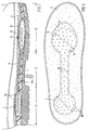
- the outsole construction shown schematically in FIGS. 1 to 4 comprises a rubber sole 1, insole 2, a damping wedge 3 arranged between insole 2 and rubber sole 1, preferably made of closed-pore material, in particular PU foam.
- the aforementioned outsole is connected to the upper leather 4 of a shoe in a conventional manner.
- a passage 5 is formed in the damping wedge 3, which comprises a circular opening in the heel area and an oval opening in the forefoot area, the two openings being connected to one another by a web-like opening extending in the longitudinal direction of the outsole .
- a separate damping component 6 according to FIG. 2 can be fitted into the aforementioned passage 5.
- This component 6 comprises a rear or heel pad 7, front or forefoot pad 8, and a connecting channel 9 between the two pads 7 and 8.
- the aforementioned component is filled with a fluid medium, in particular a gel-like liquid. It is a self-contained, uniformly flexible damping element, the flexibility being ensured, inter alia, by the upholstery together with the connecting channel being designed in the manner of a bag, in particular a flat bag, the walls consisting of plastic foils welded to one another at the edges.
- the edge-side welding is identified in FIGS. 1 and 2 with the reference number 10.
- the individual areas of the outsole are also identified, specifically with the reference number 11 the heel area, with the reference number 12 the midfoot area and with the reference number 13 the forefoot area. Accordingly, the rear pad 7 is located in the heel area 11, while the front pad 8 is arranged in the forefoot area 13.
- the damping component 6 is dimensioned such that it can be fitted as seamlessly as possible into the passage 5 of the pressure-elastic damping wedge.
- an extension 14 can also be seen at the rear end of the heel cushion 7, through which the component 6 is filled with the fluid medium. After filling, the neck 14 is welded with the filling opening closed.
- the damping component 6 for better adaptation of the damping component 6 to the passage 5 or a corresponding recess in the rubber sole 1, this can be designed according to FIGS. 12 and 13, the lower wall comprising the pads 7, 8 and the connecting channel 9 being made from a correspondingly deep-drawn Plastic film is made, while the upper wall 16 is formed as a cover film extending flat. After the two cushions 7 and 8 and the connecting channel 9 have been filled with the fluid medium, the cover film 16 is welded to the latter along the upper peripheral edge 17 of the lower deep-drawn wall in a conventional manner.
- the filling liquid preferably also comprises solid particles, in particular cork or plastic particles 18, by means of which the degree of damping of the component 6 can be additionally increased.
- the aforementioned solid particles also serve to visualize the fluid flow between the two pads 7 and 8 when walking with a shoe with the outsole described.
- the fluid flow when walking within the damping component 6 is indicated in FIGS. 5 and 6.
- the heel pad 7 is loaded (part 19). Accordingly, damping fluid is displaced from the heel pad 7, namely through the connecting channel 9 into the front or forefoot cushion 8.
- the corresponding fluid flow is identified in FIG. 5 with the multiple arrows 20. In this way, the shock load on the heel is absorbed or damped. The foot then rolls over the forefoot area in accordance with FIG. 6.
- the front or forefoot cushion 8 is loaded (arrow 21).
- the heel pad 7 is relieved.
- the damping fluid within the component 6 can accordingly flow back from the front or forefoot cushion 8 back into the heel cushion 7 according to the multiple arrows 22 in FIG. 6.
- this fluid displacement relieves the forefoot; on the other hand, the heel pad 7 is refilled so that it is ready for a new shock absorption when the heel hits the ground.
- the diameter of the heel pad 7 is between approximately 40 to 50 mm, in particular approximately 45 mm.
- the forefoot pad 8 is preferably somewhat wider and longer than the heel pad 7. However, it is built flatter than the heel pad 7 in accordance with the lower height of the outsole in the forefoot area. Preferably, however, the two pads 7 and 8 are of equal volume, so that the almost complete emptying of one pad results in the almost complete filling of the other pad.
- the connecting channel between the two pads 7 and 8 preferably has an average diameter of approximately 11 to 20 mm, in particular approximately 15 to 17 mm.
- the length of the connecting channel 9 depends on the respective shoe size.
- a viewing window should be assigned to at least the connecting channel 9. In the simplest embodiment, this is located on the underside of the outsole.
- the rubber sole 1 in the area of the connecting channel 9, a transparent plastic part is used.
- a corresponding viewing window is identified in FIG. 7 by reference number 23.
- two further viewing windows 24 and 25 are integrated in the rubber sole 1, the viewing window 24 being assigned to the forefoot cushion 8 and the viewing window 25 to the heel cushion 7. These viewing windows are also insert parts made of transparent plastic.
- the surface of the viewing window has a waffle structure.
- the surface of the viewing window is characterized by a knob structure.
- the surface of the viewing window has 23, 24 and / or 25 spikes or pointed-edged elevations.
- the viewing windows 23, 24 and / or 25 can preferably also each include a magnifying lens in order to be able to better recognize the fluid flow between the two pads 7 and 8.
- a side viewing window 26 is formed towards the heel cushion 7 in the heel region. Otherwise, the outsole construction according to FIG. 11 corresponds to that according to FIGS. 1 to 4.
- the arrangement of lateral viewing windows in the area of the connecting channel 9 is particularly attractive.
- An embodiment for this is shown in FIG. 14.
- the connecting channel 9 is divided into two branches 9 'and 9''. These two channel branches are each shifted towards the outside of the damping wedge 3, and in each case past a side viewing window 27 or 28. Through these two viewing windows, the fluid flow through the connecting channel 9 or 9 ', 9''can also be observed while walking.
- the free flow cross section the connecting channel branches 9 'and 9'' is approximately half the size of the flow cross section of a single connecting channel 9 according to the above-described embodiments.
- the connecting channel 9 between the two cushions 7 and 8 can be provided from the outside, i. H. fluid throttle adjustable by the user, e.g. B. in the form of a throttle screw acting on the connecting channel 9.
- This can e.g. B. be screwed from the bottom into an incorporated in the rubber sole 1 thread.
- a throttle screw is indicated in FIG. 1 by the double arrows 29.
- the damping component 6 is only partially, in particular 2/3 of its maximum volume, filled with the fluid medium.
- the component can be filled with a liquid medium in the absence of air. However, it is preferably carried out by including a predetermined volume of air or inert gas, in particular nitrogen. In this way, a compressible displacement space is created within the component 6.
- the degree of damping of the component 6 can be adjusted in that it contains an elastically flexible, in particular open-pored sponge or the like, through which the damping fluid must be displaced. In this way, the sponge represents an additional throttle.
- the insole 2 should have the conventional rigidity. Accordingly, the pads 7 and 8 and the connecting channel 9 do not exert any noticeable pressure on the user's foot when walking with the one described Outsole.
- the component 6 does not have the function of an arch support, but serves as an active damping element, preferably in conjunction with a passive damping element, as is known, for. B. represents the damping wedge 3.
Landscapes
- Footwear And Its Accessory, Manufacturing Method And Apparatuses (AREA)
Description
- Die Erfindung betrifft eine Laufsohle, insbesondere für einen Wander- oder Bergschuh, mit zwei zumindest teilweise mit einem fluiden Medium gefüllten und durch einen Kanal miteinander verbundenen Polstern, von denen das eine im Fersenbereich und das andere im vorderen Bereich der Laufsohle angeordnet ist, wobei die Polster samt Verbindungskanal als in sich geschlossenes und einheitliches flexibles Bauteil in einen entsprechend bemessenen Hohlraum der Laufsohle einpaßbar sind und der Verbindungskanal so bemessen ist, daß das andere, im vorderen Bereich der Laufsohle angeordnete Polster im Vorfußbereich, insbesondere Fußballenbereich, liegt.
- Eine derartige Laufsohle ist aus der US-A-4,446,634 bekannt. Diese Laufsohle zeichnet sich zum einen dadurch aus, daß das mit fluidem Medium gefüllte Polster als gesondertes Bauteil herstellbar und in die Sohle einsetzbar ist. Zum anderen zeichnet sich die bekannte Laufsohle durch eine kontrollierte Stoßabsorption bzw. Dämpfung und damit erhöhte Schonung von Fuß, Knie und Rücken des Benutzers aus. Das mit fluidem Medium gefüllte Polster erlaubt vor allem eine dynamische Dämpfung von Fuß, Knie und Rücken beim Abrollen des Fußes auf dem Boden.
- Ausgehend von dem vorgenannten Stand der Technik liegt der vorliegenden Erfindung die Aufgabe zugrunde, Maßnahmen aufzuzeigen, mit denen sich der Dämpfungsgrad der Füllflüssigkeit für die in der Laufsohle eingepaßten Polster sowohl erhöhen als auch gezielter einstellen läßt. Auch soll durch die erwähnten Maßnahmen die Akzeptanz der erfindungsgemäßen Laufsohle bzw. eines damit versehenen Schuhs beim Verbraucher erhöht werden.
- Die vorgenannte Aufgabe wird bei einer Laufsohle der eingangs genannten Art dadurch gelöst, daß das fluide Medium Feststoffpartikel, insbesondere Kork oder Kunststoffpartikel umfaßt und daß die Laufsohle zumindest im Bereich des Verbindungskanals zwischen den beiden Polstern ein Sichtfenster aufweist, durch das hindurch die fluide Strömung zwischen den beiden Polstern beobachtbar ist.
- Durch die erfindungsgemäß vorgesehenen Feststoffpartikel läßt sich der Dämpfungsgrad der Füllflüssigkeit für die beiden in der Laufsohle eingepaßten Polster sowohl erhöhen als auch bedarfsweise einstellen, ohne daß es einer aufwendigen Ventil- und Drosseleinrichtung bedarf. Die Feststoffpartikel dienen darüber hinaus in Verbindung mit dem erfindungsgemäß vorgesehenen Sichtfenster zur Sichtbarmachung der Fluidströmung zwischen dem vorderen und hinteren Polster. Damit läßt sich die Akzeptanz der erfindungsgemäßen Laufsohle beim Verbraucher erheblich erhöhen. Dies gilt insbesondere in Verbindung mit den Maßnahmen nach Anspruch 3, wonach die Feststoffpartikel in Kontrast zum fluidem Medium gefärbt sind. Ist die Füllflüssigkeit z. B. blau, so eignen sich weiße Kunststoffpartikel als Feststoffpartikel zur Sichtbarmachung der Fluidströmung im Verbindungskanal.
- Die vorgenannten Sichtfenster können entsprechend den Ansprüchen 4 bis 7 angeordnet sein, wobei die Ausbildung nach Anspruch 7 es ermöglicht, die Fluidströmung zwischen den beiden Polstern beim Gehen zu beobachten, und zwar dann, wenn ein anderer einen mit einer erfindungsgemäßen Laufsohle versehenen Schuh trägt. Außerdem läßt sich bei dieser Ausführungsform die Fluidströmung zwischen den beiden Polstern sehr gut auf einem Tisch oder dergleichen demonstrieren.
- Um die Verdrängung des Füllmediums während des Gehens vom vorderen Polster zum hinteren Polster und umgekehrt zu ermöglichen, muß genügend Volumen zur Aufnahme des verdrängten Mediums vorhanden sein. Dies gilt insbesondere dann, wenn die Wandung des mit Medium gefüllten Bauteils nicht dehnbar ist. In diesem Fall ist das durch die beiden Polster und deren Verbindungskanal gebildete Bauteil nur zu einem Teil, insbesondere zu etwa 2/3 seines maximalen Volumens gefüllt. Die Füllung des Bauteils mit Flüssigkeit kann dabei unter Luftausschluß erfolgen. Vorzugsweise erfolgt sie jedoch unter Einschluß eines vorbestimmten Luft- oder Inertgas-, insbesondere Stickstoff-Volumens, welches bedarfsweise kompressibel ist, so daß Verdrängungsvolumen je nach Bedarf geschaffen wird.
- Zusätzlich kann die Füllung des Bauteils einen elastisch nachgiebigen Schwamm umfassen, und zwar vorzugsweise offenporigen Schwamm. Mit einem solchen Schwamm läßt sich der Dämpfungsgrad zusätzlich einstellen.
- Nachstehend werden anhand der beigefügten Zeichnung Ausführungsbeispiele der erfindungsgemäß ausgebildeten Laufsohle näher erläutert. Es zeigen:
- Fig. 1
- einen Teil eines Bergschuhs zur Darstellung des Grundaufbaus einer erfindungsgemäß ausgebildeten Laufsohle, im Längsschnitt;
- Fig. 2
- ein Dämpfungs-Bauteil, welches für eine erfindungsgemäße Laufsohle Verwendung findet, in perspektivischer Ansicht;
- Fig. 3
- einen Dämpfungskeil als Teil der Laufsohle mit einer Ausnehmung zur Einpassung des Dämpfungs-Bauteils gemäß Fig. 2, ebenfalls in perspektivischer Ansicht;
- Fig. 4
- den Dämpfungskeil gemäß Fig. 3 mit eingesetztem Dämpfungs-Bauteil gemäß Fig. 2 in Draufsicht;
- Fig. 5
- einen Bergschuh mit erfindungsgemäßer Laufsohle unter Belastung der Ferse und unter Darstellung einer Fluidströmung innerhalb des Dämpfungs-Bauteils gemäß Fig. 2 von der Ferse zum Vorfuß;
- Fig. 6
- einen Bergschuh unter Belastung des Vorfußbereichs und unter Darstellung einer Fluidströmung in dem Dämpfungs-Bauteil gemäß Fig. 2 vom Vorfuß zur Ferse;
- Fig. 7
- eine erfindungsgemäß ausgebildete Laufsohle in Unteransicht unter Darstellung von Sichtfenstern im Bereich des Dämpfungs-Bauteils gemäß Fig. 3;
- Fig. 8 bis 10
- verschiedene Ausführungsformen von an der Unterseite der Laufsohle gesondert eingesetzten Sichtfenstern, jeweils in perspektivischer Ansicht;
- Fig. 11
- die Laufsohle gemäß Fig. 1 in perspektivischer Ansicht und unter Darstellung eines im Fersenbereich angebrachten seitlichen Sichtfensters;
- Fig. 12
- eine andere Ausführungsform eines Dämpfungs-Bauteils entsprechend Fig. 2 in Seitenansicht;
- Fig. 13
- das Dämpfungs-Bauteil gemäß Fig. 12 in perspektivischer Ansicht; und
- Fig. 14
- eine weitere Ausführungsform eines in einem Dämpfungskeil eingepaßten Dämpfungs-Bauteils mit seitlichen Sichtfenstern im Bereich des Verbindungskanals zwischen vorderem und hinterem Dämpfungs-Polster, in Draufsicht.
- Die in den Fig. 1 bis 4 schematisch dargestellte Laufsohlen-Konstruktion umfaßt eine Gummisohle 1, Brandsohle 2, einen zwischen Brandsohle 2 und Gummisohle 1 angeordneten Dämpfungskeil 3 aus vorzugsweise geschlossen-porigem Material, insbesondere PU-Schaum. Die Vorgenannte Laufsohle ist mit dem Oberleder 4 eines Schuhs in herkömmlicher Weise verbunden. Wie insbesondere der Fig. 3 entnommen werden kann, ist im Dämpfungskeil 3 ein Durchgang 5 ausgebildet, der im Fersenbereich eine kreisförmige, im Vorfußbereich eine ovale Öffnung umfaßt, wobei die beiden Öffnungen durch einen stegartigen, sich in Laufsohlen-Längsrichtung erstreckenden Durchbruch miteinander verbunden sind.
- In den vorgenannten Durchgang 5 ist ein gesondertes Dämpfungs-Bauteil 6 entsprechend Fig. 2 einpaßbar. Dieses Bauteil 6 umfaßt ein hinteres bzw. Fersenpolster 7, vorderes bzw. Vorfuß-Polster 8, sowie einen Verbindungskanal 9 zwischen den beiden Polstern 7 und 8. Das vorgenannte Bauteil ist mit einem fluiden Medium, insbesondere einer gelartigen Flüssigkeit gefüllt. Es stellt ein in sich geschlossenes, einheitlich flexibles Dämpfungselement dar, wobei die Flexibilität unter anderem dadurch gewährleistet ist, daß die Polster samt Verbindungskanal nach Art eines Beutels, insbesondere Flachbeutels ausgebildet sind, wobei die Wände aus randseitig miteinander verschweißten Kunststoffolien bestehen. Die randseitige Verschweißung ist in den Fig. 1 und 2 mit der Bezugsziffer 10 gekennzeichnet.
- In Fig. 1 sind auch noch die einzelnen Bereiche der Laufsohle gekennzeichnet, und zwar mit der Bezugsziffer 11 der Fersen-Bereich, mit der Bezugsziffer 12 der Mittelfuß-Bereich und mit der Bezugsziffer 13 der Vorfuß-Bereich. Dementsprechend liegt das hintere Polster 7 im Fersenbereich 11, während das vordere Polster 8 im Vorfuß-Bereich 13 angeordnet ist.
- Das Dämpfungs-Bauteil 6 ist so bemessen, daß es in den Durchgang 5, des druckelastischen Dämpfungskeils möglichst lückenlos einpaßbar ist.
- In Fig. 2 ist am hinteren Ende des Fersenpolsters 7 noch ein Ansatz 14 erkennbar,durch den hindurch die Befüllung des Bauteils 6 mit dem fluiden Medium erfolgt. Nach Befüllung wird der Ansatz 14 unter Schließung der Füllöffnung verschweißt.
- Zur besseren Anpassung des Dämpfungs-Bauteils 6 an den Durchgang 5 oder eine entsprechende Ausnehmung in der Gummisohle 1 kann dieses entsprechend den Fig. 12 und 13 ausgebildet sein, wobei die die Polster 7, 8 und den Verbindungskanal 9 umfassende untere Wand aus einer entsprechend tiefgezogenen Kunststofffolie besteht, während die oberen Wand 16 als sich eben erstreckende Deckfolie ausgebildet ist. Die Deckfolie 16 wird nach Befüllung der beiden Polster 7 und 8 sowie des Verbindungskanals 9 mit dem fluiden Medium längs des oberen Umfangsrandes 17 der unteren tiefgezogenen Wand mit dieser in herkömmlicher Weise verschweißt.
- Die Fig. 12 und 13 zeigen auch noch sehr deutlich die keilförmige Verjüngung des Dämpfungs-Bauteils 6 in Richtung von der Ferse zum Vorfuß in Anpassung an die entsprechende Verjüngung der Laufsohle bzw. des Dämpfungskeils 3 bei der Ausführungsform nach den Fig. 1 bis 4.
- Die Füllflüssigkeit umfaßt vorzugsweise noch Feststoffpartikel, insbesondere Kork- oder Kunststoffpartikel 18, durch die der Dämpfungsgrad des Bauteils 6 zusätzlich erhöht werden kann.
- Bei Anordnung mindestens eines Sichtfensters im Bereich des Verbindungskanals 9 dienen die vorgenannten Feststoffpartikel zugleich zur Sichtbarmachung der Fluidströmung zwischen den beiden Polstern 7 und 8 beim Gehen mit einem Schuh mit der beschriebenen Laufsohle. Die Fluidströmung beim Gehen innerhalb des Dämpfungs-Bauteils 6 ist in den Fig. 5 und 6 angedeutet. Beim Auftreten mit der Ferse (Fig. 5) wird das Fersenpolster 7 belastet (Teil 19). Dementsprechend wird Dämpfungsflüssigkeit aus dem Fersenpolster 7 verdrängt, und zwar durch den Verbindungskanal 9 hindurch in das vordere bzw. Vorfuß-Polster 8 hinein. Die entsprechende Fluidströmung ist in Fig. 5 mit den Mehrfach-Pfeilen 20 gekennzeichnet. Auf diese Weise wird die Stoßbelastung der Ferse absorbiert bzw. gedämpft. Anschließend erfolgt das Abrollen des Fußes über den Vorfußbereich entsprechend Fig. 6. Dementsprechend wird beim Abrollen des Fußes über den Vorfuß-Bereich das vordere bzw. Vorfuß-Polster 8 belastet (Pfeil 21). Das Fersenpolster 7 ist entlastet. Das Dämpfungsfluid innerhalb des Bauteils 6 kann dementsprechend vom vorderen bzw. Vorfuß-Polster 8 wieder in das Fersenpolster 7 zurückströmen entsprechend den Mehrfach-Pfeilen 22 in Fig. 6. Durch diese Flüssigkeits-Verdrängung wird zum einen der Vorfuß entlastet; zum anderen wird das Fersenpolster 7 wieder gefüllt, so daß dieses für eine erneute Stoßdämpfung beim Auftreffen der Ferse auf den Boden bereit ist.
- Bei einer bevorzugten Ausführungsform beträgt der Durchmesser des Fersenpolsters 7 zwischen etwa 40 bis 50 mm, insbesondere etwa 45 mm. Das Vorfuß-Polster 8 ist vorzugsweise etwas breiter und länger als das Fersenpolster 7 ausgebildet. Es ist jedoch flacher gebaut als das Fersenpolster 7 entsprechend der geringeren Bauhöhe der Laufsohle im Vorfuß-Bereich. Vorzugsweise sind die beiden Polster 7 und 8 jedoch volumengleich ausgebildet, so daß die nahezu vollständige Entleerung des einen Polsters die nahezu vollständige Befüllung des anderen Polsters zur Folge hat.
- Der Verbindungskanal zwischen den beiden Polstern 7 und 8 weist vorzugsweise einen mittleren Durchmesser von etwa 11 bis 20 mm, insbesondere etwa 15 bis 17 mm auf. Die Länge des Verbindungskanals 9 hängt von der jeweiligen Schuhgröße ab.
- Wie bereits oben ausgeführt, soll zumindest dem Verbindungskanal 9 ein Sichtfenster zugeordnet sein. Dieses befindet sich bei der einfachsten Ausführungsform an der Unterseite der Laufsohle. Zu diesem Zweck wird in die Gummisohle 1 im Bereich des Verbindungskanals 9 ein transparentes Kunststoffteil eingesetzt. In Fig. 7 ist ein entsprechendes Sichtfenster mit der Bezugsziffer 23 gekennzeichnet.
- Bei der Ausführungsform nach Fig. 7 sind in der Gummisohle 1 zwei weitere Sichtfenster 24 und 25 integriert, wobei das Sichtfenster 24 dem Vorfuß-Polster 8 und das Sichtfenster 25 dem Fersen-Polster 7 zugeordnet ist. Auch diese Sichtfenster sind Einsatzteile aus transparentem Kunststoff.
- Die Fig. 8 bis 10 zeigen unterschiedliche Strukturen der Sichtfenster-Oberflächen. Bei der Ausführungsform nach Fig. 8 hat die Oberfläche des Sichtfensters Waffelstruktur. Bei der Ausführungsform nach Fig. 9 ist die Oberfläche des Sichtfensters durch eine Noppenstruktur gekennzeichnet. Bei der Ausführungsform nach Fig. 10 weist die Oberfläche des Sichtfensters 23, 24 und/oder 25 Spikes bzw. spitzkantige Erhebungen auf. Die Sichtfenster 23, 24 und/oder 25 können vorzugsweise jeweils auch eine Vergrößerungslinse umfassen, um die Fluidströmung zwischen den beiden Polstern 7 und 8 besser erkennen zu können.
- Bei der Ausführungsform nach Fig. 11 ist im Fersenbereich ein seitliches Sichtfenster 26 zum Fersenpolster 7 hin ausgebildet. Im übrigen entspricht die Laufsohlen-Konstruktion nach Fig. 11 derjenigen nach den Fig. 1 bis 4.
- Besonders attraktiv ist die Anordnung von seitlichen Sichtfenstern im Bereich des Verbindungskanals 9. Eine Ausführungsform dafür ist in Fig. 14 dargestellt. Dort ist der Verbindungskanal 9 in zwei Äste 9' und 9'' unterteilt. Diese beiden Kanal-Äste sind jeweils zur Außenseite des Dämpfungskeils 3 hin verlagert, und zwar jeweils an einem seitlichen Sichtfenster 27 bzw. 28 vorbei. Durch diese beiden Sichtfenster kann die Fluidströmung durch den Verbindungskanal 9 bzw. 9', 9'' auch während des Gehens beobachtet werden. Der freie Strömungsquerschnitt der Verbindungskanal-Äste 9' und 9'' ist etwa halb so groß wie der Strömungsquerschnitt eines einzigen Verbindungskanals 9 entsprechend den vorbeschriebenen Ausführungsformen.
- Wie bereits eingangs ausgeführt, kann dem Verbindungskanal 9 zwischen den beiden Polstern 7 und 8 eine von außen her, d. h. durch den Benutzer verstellbare Fluiddrossel zugeordnet sein, z. B. in Form einer auf den Verbindungskanal 9 einwirkenden Drosselschraube. Diese kann z. B. von der Unterseite her in ein in der Gummisohle 1 eingearbeitetes Gewinde einschraubbar sein. In Fig. 1 ist eine derartige Drosselschraube mit den Doppelpfeilen 29 angdeutet.
- Um die gewünschte Verdrängung des fluiden Mediums zwischen den beiden Polstern 7 und 8 zu gewährleisten, ist das Dämpfungs-Bauteil 6 nur zu einem Teil, insbesondere 2/3 seines maximalen Volumens, mit dem fluiden Medium gefüllt.
- Die Füllung des Bauteils mit einem flüssigen Medium kann unter Luftausschluß erfolgen. Vorzugsweise erfolgt sie jedoch unter Einschluß eines vorbestimmten Luft- oder Inertgas-, insbesondere Stickstoffvolumens. Auf diese Weise wird ein kompressibler Verdrängungsraum innerhalb des Bauteils 6 geschaffen.
- Zusätzlich kann der Dämpfungsgrad des Bauteils 6 dadurch eingestellt werden, daß es einen elastisch nachgiebigen, insbesondere offenporigen Schwamm oder dgl. beinhaltet, durch den hindurch das Dämpfungsfluid verdrängt werden muß. Der Schwamm stellt auf diese Weise eine zusätzliche Drossel dar.
- Wie bereits eingangs dargelegt, soll die Brandsohle 2 die herkömmliche Steifigkeit aufweisen. Dementsprechend üben die Polster 7 und 8 sowie der Verbindungskanal 9 keinen spürbaren Druck auf den Fuß des Benutzers beim Gehen mit der beschriebenen Laufsohle aus. Das Bauteil 6 hat nicht die Funktion einer Fußgewölbestütze, sondern dient als aktives Dämpfungselement, vorzugsweise in Verbindung mit einem passiven Dämpfungselement, wie es z. B. der Dämpfungskeil 3 darstellt.
- Sämtliche in den Anmeldungsunterlagen offenbarten Merkmale werden als erfindungswesentlich beansprucht, soweit sie einzeln oder in Kombination gegenüber dem Stand der Technik neu sind.
Claims (15)
- Laufsohle, insbesondere für einen Wander- oder Bergschuh, mit zwei zumindest teilweise mit einem fluiden Medium gefüllten und durch einen Kanal (9) miteinander verbundenen Polstern (7, 8), von denen das eine (7) im Fersenbereich (11) und das andere (8) im vorderen Bereich der Laufsohle angeordnet ist, wobei die Polster (7, 8) samt Verbindungskanal (9) als in sich geschlossenes und einheitlich flexibles Bauteil in einen entsprechend bemessenen Hohlraum (5) der Laufsohle einpaßbar sind und der Verbindungskanal so bemessen ist, daß das andere, im vorderen Bereich der Laufsohle angeordnete Polster (8) im Vorfußbereich (13), insbesondere Fußballenbereich, liegt,
dadurch gekennzeichnet, daß
das fluide Medium Feststoffpartikel, insbesondere Kork- oder Kunststoffpartikel (18) umfaßt, und daß die Laufsohle zumindest im Bereich des Verbindungskanals (9) zwischen den beiden Polstern (7, 8) ein Sichtfenster (23) aufweist, durch das hindurch die Fluidströmung zwischen den beiden Polstern (7, 8) beobachtbar ist. - Laufsohle nach Anspruch 1,
dadurch gekennzeichnet, daß als fluides Medium eine gelartige Flüssigkeit dient. - Laufsohle nach Anspruch 1 oder 2,
dadurch gekennzeichnet, daß die Feststoffpartikel (18) im Kontrast zum fluiden Medium gefärbt sind, so daß sie und damit die Fluidströmung zwischen den beiden Polstern (7, 8) durch das Sichtfenster (23) hindurch gut erkennbar sind. - Laufsohle nach einem der Ansprüche 1 bis 3,
dadurch gekennzeichnet, daß auch im Bereich der beiden Polster (7, 8) Sichtfenster (24, 25) ausgebildet sind. - Laufsohle nach Anspruch 1 und/oder 4,
dadurch gekennzeichnet, daß die Sichtfenster (23, 24, 25) an der unteren Laufseite der Sohle liegen und durch transparente Laufsohlen-Einsätze (Fig. 8 bis 10) gebildet sind. - Laufsohle nach Anspruch 4 oder 5,
dadurch gekennzeichnet, daß wenigstens im Fersenbereich (11) der Laufsohle ein seitliches Sichtfenster (26) zum im Fersenbereich (11) angeordneten Polster (7) hin ausgebildet ist. - Laufsohle nach einem der Ansprüche 1 bis 6,
dadurch gekennzeichnet, daß der Verbindungskanal (9; 9', 9'') zwischen den beiden Polstern (7, 8) im Mittelfußbereich (12) zur Außenseite der Laufsohle hin geführt ist, so daß durch ein dort angebrachtes seitliches Sichtfenster (27 und/oder 28) hindurch die Fluidströmung im Verbindungskanal (9; 9', 9'') während des Gehens beobachtbar ist. - Laufsohle nach einem der Ansprüche 1 bis 7,
dadurch gekennzeichnet, daß das durch die beiden Polster (7, 8) und deren Verbindungskanal (9) gebildete Bauteil (6) nur zu einem Teil, insbesondere etwa 2/3 seines maximalen Volumens, mit einem flüssigen Medium gefüllt ist. - Laufsohle nach Anspruch 8,
dadurch gekennzeichnet, daß die Füllung des Bauteils (6) mit einem flüssigen Dämpfungsmedium unter Luftausschluß erfolgt. - Laufsohle nach Anspruch 8,
dadurch gekennzeichnet, daß die Füllung des Bauteils (6) mit einem flüssigen Dämpfungsmedium unter Einschluß eines vorbestimmten Luft- oder Inertgas-, insbesondere Stickstoffvolumens, erfolgt. - Laufsohle nach einem der Ansprüche 8 bis 10,
dadurch gekennzeichnet, daß die Füllung des Bauteils (6) einen elastisch nachgiebigen, insbesondere offenporigen Schwamm umfaßt. - Laufsohle nach einem der Ansprüche 1 bis 11,
dadurch gekennzeichnet, daß der Hohlraum (5) für die Aufnahme der Polster (7, 8) samt Verbindungskanal (9) innerhalb eines gesonderten, unterhalb der Brandsohle (2) angeordneten Dämpfungskeils (3) ausgebildet ist. - Laufsohle nach Anspruch 12,
dadurch gekennzeichnet, daß der Dämpfungskeil (3) aus PU-Schaum, einer Kork-Kautschuk-Mischung oder dgl. Dämpfungsmaterial hergestellt ist. - Laufsohle nach einem der Ansprüche 1 bis 13,
dadurch gekennzeichnet, daß die Polster (7, 8) samt Verbindungskanal (9) nach Art eines Beutels, insbesondere Flachbeutels, ausgebildet sind, wobei die Wände aus randseitig miteinander verschweißten Kunststoffolien bestehen. - Laufsohle nach Anspruch 14,
dadurch gekennzeichnet, daß die eine Wand (15) unter Ausbildung der beiden Polster (7, 8) und des Verbindungskanals (9) tiefgezogen ist, während die andere Wand durch eine sich eben erstreckende Deckfolie (16) gebildet ist.
Applications Claiming Priority (3)
| Application Number | Priority Date | Filing Date | Title |
|---|---|---|---|
| DE4200041A DE4200041A1 (de) | 1992-01-02 | 1992-01-02 | Laufsohle, insbesondere fuer einen wander- oder bergschuh |
| DE4200041 | 1992-01-02 | ||
| PCT/EP1992/003008 WO1993012685A1 (de) | 1992-01-02 | 1992-12-30 | Laufsohle, insbesondere für einen wander- oder bergschuh |
Publications (2)
| Publication Number | Publication Date |
|---|---|
| EP0620712A1 EP0620712A1 (de) | 1994-10-26 |
| EP0620712B1 true EP0620712B1 (de) | 1996-04-17 |
Family
ID=6449077
Family Applications (1)
| Application Number | Title | Priority Date | Filing Date |
|---|---|---|---|
| EP93902136A Expired - Lifetime EP0620712B1 (de) | 1992-01-02 | 1992-12-30 | Laufsohle, insbesondere für einen wander- oder bergschuh |
Country Status (5)
| Country | Link |
|---|---|
| EP (1) | EP0620712B1 (de) |
| AT (1) | ATE136743T1 (de) |
| DE (2) | DE4200041A1 (de) |
| ES (1) | ES2089785T3 (de) |
| WO (1) | WO1993012685A1 (de) |
Families Citing this family (36)
| Publication number | Priority date | Publication date | Assignee | Title |
|---|---|---|---|---|
| DE9321113U1 (de) * | 1993-09-16 | 1996-05-15 | Kingsmoss Holding N.V., Willemstad | Schuhsystem |
| US6453577B1 (en) | 1996-02-09 | 2002-09-24 | Reebok International Ltd. | Support and cushioning system for an article of footwear |
| CA2181998C (en) * | 1994-01-26 | 2003-05-13 | Paul E. Litchfield | Cushioning member for an article of footwear |
| US5771606A (en) * | 1994-10-14 | 1998-06-30 | Reebok International Ltd. | Support and cushioning system for an article of footwear |
| US6505420B1 (en) | 1996-02-09 | 2003-01-14 | Reebok International Ltd. | Cushioning member for an article of footwear |
| TW286269B (de) * | 1994-11-28 | 1996-09-21 | Marion Frank Rudy | |
| US5671552A (en) * | 1995-07-18 | 1997-09-30 | Pettibone; Virginia G. | Atheletic shoe |
| US5706589A (en) * | 1996-06-13 | 1998-01-13 | Marc; Michel | Energy managing shoe sole construction |
| NZ314180A (en) * | 1997-02-03 | 1998-05-27 | Chan Jang Plastics Co Ltd | Sole pad with liquid-filled pads housed in and projecting from an obliquely oriented and a straight recess in the pad |
| US5894687A (en) * | 1997-06-18 | 1999-04-20 | Gnan-Jang Plastics Co., Ltd. | Shoe pad having massaging effect |
| US5950332A (en) * | 1997-08-28 | 1999-09-14 | Lain; Cheng Kung | Fluid circulating cushioned insole |
| US5993585A (en) * | 1998-01-09 | 1999-11-30 | Nike, Inc. | Resilient bladder for use in footwear and method of making the bladder |
| AT408712B (de) * | 1999-07-29 | 2002-02-25 | Weigl Christine | Schuh |
| US6354020B1 (en) | 1999-09-16 | 2002-03-12 | Reebok International Ltd. | Support and cushioning system for an article of footwear |
| US6971193B1 (en) * | 2002-03-06 | 2005-12-06 | Nike, Inc. | Bladder with high pressure replenishment reservoir |
| US7426792B2 (en) | 2002-05-09 | 2008-09-23 | Nike, Inc. | Footwear sole component with an insert |
| US6796056B2 (en) * | 2002-05-09 | 2004-09-28 | Nike, Inc. | Footwear sole component with a single sealed chamber |
| US6745499B2 (en) | 2002-05-24 | 2004-06-08 | Reebok International Ltd. | Shoe sole having a resilient insert |
| US7080467B2 (en) | 2003-06-27 | 2006-07-25 | Reebok International Ltd. | Cushioning sole for an article of footwear |
| US7353625B2 (en) | 2003-11-03 | 2008-04-08 | Reebok International, Ltd. | Resilient cushioning device for the heel portion of a sole |
| US7383648B1 (en) | 2004-02-23 | 2008-06-10 | Reebok International Ltd. | Inflatable support system for an article of footwear |
| US7448150B1 (en) | 2004-02-26 | 2008-11-11 | Reebok International Ltd. | Insert with variable cushioning and support and article of footwear containing same |
| US7222443B2 (en) * | 2004-03-11 | 2007-05-29 | Rocky Brands Wholesale Llc | Footwear with improved insole |
| US20050241185A1 (en) * | 2004-04-28 | 2005-11-03 | Flood Michael T | Shoe insert |
| US7622014B2 (en) | 2005-07-01 | 2009-11-24 | Reebok International Ltd. | Method for manufacturing inflatable footwear or bladders for use in inflatable articles |
| KR101008305B1 (ko) * | 2010-07-05 | 2011-01-14 | 김성순 | 에어백을 갖는 신발 안창 |
| US20130008050A1 (en) * | 2011-07-07 | 2013-01-10 | Michel Marc | Shoe Insole |
| WO2016164549A1 (en) | 2015-04-08 | 2016-10-13 | Nike Innovate C.V. | Article including a bladder element with an image and method of manufacturing the article |
| WO2016164550A1 (en) | 2015-04-08 | 2016-10-13 | Nike Innovate C.V. | Article with overlay secured to bladder element over image and method of manufacturing the article |
| US9974360B2 (en) | 2015-04-08 | 2018-05-22 | Nike, Inc. | Method of manufacturing a bladder element with an etched feature and article having a bladder element with an etched feature |
| US9820531B2 (en) | 2015-05-29 | 2017-11-21 | Nike, Inc. | Footwear including an incline adjuster |
| US10932523B2 (en) | 2015-11-30 | 2021-03-02 | Nike, Inc. | Electrorheological fluid structure with attached conductor and method of fabrication |
| EP4094615B1 (de) | 2017-08-31 | 2024-07-10 | Nike Innovate C.V. | Schuh mit einem neigungsanpasser |
| KR102371884B1 (ko) | 2017-08-31 | 2022-03-08 | 나이키 이노베이트 씨.브이. | 다수의 개별 챔버를 갖는 경사 조절기 |
| EP3694361B1 (de) | 2017-10-13 | 2024-08-07 | NIKE Innovate C.V. | Schuhzwischensohle mit elektrorheologischem flüssigkeitsgehäuse |
| US11186055B2 (en) | 2018-03-01 | 2021-11-30 | Nike, Inc. | Method of manufacturing fluid-filled chambers |
Family Cites Families (7)
| Publication number | Priority date | Publication date | Assignee | Title |
|---|---|---|---|---|
| US4100686A (en) * | 1977-09-06 | 1978-07-18 | Sgarlato Thomas E | Shoe sole construction |
| FR2452889A1 (fr) * | 1979-04-03 | 1980-10-31 | Reber Walter | Dispositif destine a faciliter la locomotion de l'homme se deplacant a pied sur le sol |
| SE8102124L (sv) * | 1981-04-02 | 1982-10-03 | Lars Gustaf Birger Peterson | Skosula |
| GB2114425B (en) * | 1982-02-05 | 1985-05-30 | Clarks Ltd | Sole units for footwear |
| US4446634A (en) * | 1982-09-28 | 1984-05-08 | Johnson Paul H | Footwear having improved shock absorption |
| US4779359A (en) * | 1987-07-30 | 1988-10-25 | Famolare, Inc. | Shoe construction with air cushioning |
| FR2663208A1 (fr) * | 1990-06-15 | 1991-12-20 | Jeanrot Patrick | Chaussure articulee. |
-
1992
- 1992-01-02 DE DE4200041A patent/DE4200041A1/de not_active Withdrawn
- 1992-12-30 DE DE59206070T patent/DE59206070D1/de not_active Expired - Fee Related
- 1992-12-30 ES ES93902136T patent/ES2089785T3/es not_active Expired - Lifetime
- 1992-12-30 WO PCT/EP1992/003008 patent/WO1993012685A1/de not_active Ceased
- 1992-12-30 EP EP93902136A patent/EP0620712B1/de not_active Expired - Lifetime
- 1992-12-30 AT AT93902136T patent/ATE136743T1/de not_active IP Right Cessation
Also Published As
| Publication number | Publication date |
|---|---|
| WO1993012685A1 (de) | 1993-07-08 |
| DE59206070D1 (de) | 1996-05-23 |
| ES2089785T3 (es) | 1996-10-01 |
| DE4200041A1 (de) | 1993-08-05 |
| EP0620712A1 (de) | 1994-10-26 |
| ATE136743T1 (de) | 1996-05-15 |
Similar Documents
| Publication | Publication Date | Title |
|---|---|---|
| EP0620712B1 (de) | Laufsohle, insbesondere für einen wander- oder bergschuh | |
| DE2164921C3 (de) | Sportschuh, insbesondere Ski-Schuh | |
| EP0999764B1 (de) | Schuh | |
| DE69518021T2 (de) | Schuhaufbau mit inneren Polsterrippen | |
| DE3713786C2 (de) | Einlegesohle für Schuhwerk | |
| DE60308830T2 (de) | Blase mit hochdruckauffüllreservoir | |
| DE19953147B4 (de) | Stoßabsorberstruktur für Schuhsohlen | |
| DE2215098A1 (de) | Sportschuh | |
| DE2852867A1 (de) | Fusskissen | |
| DE20321738U1 (de) | Innensohle mit verbesserter Polsterungs- und anatomischer Zentrierungseinrichtung | |
| DE1485772C3 (de) | ||
| DE3812186A1 (de) | Sandale | |
| EP0074568A1 (de) | Schuh | |
| EP2323512B1 (de) | Schuhsohle | |
| DE68926964T2 (de) | Einlageglied zur verwendung bei athletikschuhen | |
| DE3120349A1 (de) | Golfschuhe | |
| DE102014107751A1 (de) | Schuh, insbesondere Laufschuh | |
| DE102010060419B4 (de) | Einlage mit sensomotorischen Stimulationselementen | |
| DE68915090T2 (de) | Schuh mit Sichtfenster zum Durchblick auf Dämpfungselemente. | |
| CH718290A2 (de) | Sohle mit variablen Dämpfungseigenschaften. | |
| DE202010010359U1 (de) | Schuh | |
| DE8900237U1 (de) | Innensohle mit einer die Fußsohlen belüftenden Oberseite | |
| DE19601344C2 (de) | Einlegesohle | |
| CH702899A1 (de) | Schuhsohle und schuh. | |
| EP2305057A1 (de) | Gehgeräteboden |
Legal Events
| Date | Code | Title | Description |
|---|---|---|---|
| PUAI | Public reference made under article 153(3) epc to a published international application that has entered the european phase |
Free format text: ORIGINAL CODE: 0009012 |
|
| 17P | Request for examination filed |
Effective date: 19940421 |
|
| AK | Designated contracting states |
Kind code of ref document: A1 Designated state(s): AT BE CH DE ES FR IT LI LU NL |
|
| 17Q | First examination report despatched |
Effective date: 19950601 |
|
| GRAH | Despatch of communication of intention to grant a patent |
Free format text: ORIGINAL CODE: EPIDOS IGRA |
|
| GRAA | (expected) grant |
Free format text: ORIGINAL CODE: 0009210 |
|
| AK | Designated contracting states |
Kind code of ref document: B1 Designated state(s): AT BE CH DE ES FR IT LI LU NL |
|
| REF | Corresponds to: |
Ref document number: 136743 Country of ref document: AT Date of ref document: 19960515 Kind code of ref document: T |
|
| REG | Reference to a national code |
Ref country code: CH Ref legal event code: NV Representative=s name: RITSCHER & SEIFERT PATENTANWAELTE VSP |
|
| REF | Corresponds to: |
Ref document number: 59206070 Country of ref document: DE Date of ref document: 19960523 |
|
| ITF | It: translation for a ep patent filed | ||
| ET | Fr: translation filed | ||
| REG | Reference to a national code |
Ref country code: ES Ref legal event code: FG2A Ref document number: 2089785 Country of ref document: ES Kind code of ref document: T3 |
|
| REG | Reference to a national code |
Ref country code: ES Ref legal event code: FG2A Ref document number: 2089785 Country of ref document: ES Kind code of ref document: T3 |
|
| PGFP | Annual fee paid to national office [announced via postgrant information from national office to epo] |
Ref country code: CH Payment date: 19970103 Year of fee payment: 5 |
|
| PGFP | Annual fee paid to national office [announced via postgrant information from national office to epo] |
Ref country code: FR Payment date: 19970120 Year of fee payment: 5 |
|
| PGFP | Annual fee paid to national office [announced via postgrant information from national office to epo] |
Ref country code: BE Payment date: 19970123 Year of fee payment: 5 |
|
| PGFP | Annual fee paid to national office [announced via postgrant information from national office to epo] |
Ref country code: NL Payment date: 19970131 Year of fee payment: 5 Ref country code: ES Payment date: 19970131 Year of fee payment: 5 |
|
| PLBE | No opposition filed within time limit |
Free format text: ORIGINAL CODE: 0009261 |
|
| STAA | Information on the status of an ep patent application or granted ep patent |
Free format text: STATUS: NO OPPOSITION FILED WITHIN TIME LIMIT |
|
| 26N | No opposition filed | ||
| PGFP | Annual fee paid to national office [announced via postgrant information from national office to epo] |
Ref country code: LU Payment date: 19970709 Year of fee payment: 5 |
|
| PG25 | Lapsed in a contracting state [announced via postgrant information from national office to epo] |
Ref country code: LU Free format text: LAPSE BECAUSE OF NON-PAYMENT OF DUE FEES Effective date: 19971230 |
|
| PG25 | Lapsed in a contracting state [announced via postgrant information from national office to epo] |
Ref country code: LI Free format text: LAPSE BECAUSE OF NON-PAYMENT OF DUE FEES Effective date: 19971231 Ref country code: FR Free format text: THE PATENT HAS BEEN ANNULLED BY A DECISION OF A NATIONAL AUTHORITY Effective date: 19971231 Ref country code: ES Free format text: LAPSE BECAUSE OF THE APPLICANT RENOUNCES Effective date: 19971231 Ref country code: CH Free format text: LAPSE BECAUSE OF NON-PAYMENT OF DUE FEES Effective date: 19971231 Ref country code: BE Free format text: LAPSE BECAUSE OF NON-PAYMENT OF DUE FEES Effective date: 19971231 |
|
| BERE | Be: lapsed |
Owner name: KNEISSL DACHSTEIN SPORTARTIKEL A.G. Effective date: 19971231 |
|
| PG25 | Lapsed in a contracting state [announced via postgrant information from national office to epo] |
Ref country code: NL Free format text: LAPSE BECAUSE OF NON-PAYMENT OF DUE FEES Effective date: 19980701 |
|
| REG | Reference to a national code |
Ref country code: CH Ref legal event code: PL |
|
| NLV4 | Nl: lapsed or anulled due to non-payment of the annual fee |
Effective date: 19980701 |
|
| REG | Reference to a national code |
Ref country code: FR Ref legal event code: ST |
|
| PGFP | Annual fee paid to national office [announced via postgrant information from national office to epo] |
Ref country code: AT Payment date: 19991220 Year of fee payment: 8 |
|
| PG25 | Lapsed in a contracting state [announced via postgrant information from national office to epo] |
Ref country code: AT Free format text: LAPSE BECAUSE OF NON-PAYMENT OF DUE FEES Effective date: 20001230 |
|
| REG | Reference to a national code |
Ref country code: ES Ref legal event code: FD2A Effective date: 20010402 |
|
| PG25 | Lapsed in a contracting state [announced via postgrant information from national office to epo] |
Ref country code: IT Free format text: LAPSE BECAUSE OF NON-PAYMENT OF DUE FEES;WARNING: LAPSES OF ITALIAN PATENTS WITH EFFECTIVE DATE BEFORE 2007 MAY HAVE OCCURRED AT ANY TIME BEFORE 2007. THE CORRECT EFFECTIVE DATE MAY BE DIFFERENT FROM THE ONE RECORDED. Effective date: 20051230 |
|
| PGFP | Annual fee paid to national office [announced via postgrant information from national office to epo] |
Ref country code: DE Payment date: 20060223 Year of fee payment: 14 |
|
| PG25 | Lapsed in a contracting state [announced via postgrant information from national office to epo] |
Ref country code: DE Free format text: LAPSE BECAUSE OF NON-PAYMENT OF DUE FEES Effective date: 20070703 |