EP0620132A1 - Vorrichtung zum Antreiben, Führen und Lenken eines Fahrzeugrades - Google Patents
Vorrichtung zum Antreiben, Führen und Lenken eines Fahrzeugrades Download PDFInfo
- Publication number
- EP0620132A1 EP0620132A1 EP94105501A EP94105501A EP0620132A1 EP 0620132 A1 EP0620132 A1 EP 0620132A1 EP 94105501 A EP94105501 A EP 94105501A EP 94105501 A EP94105501 A EP 94105501A EP 0620132 A1 EP0620132 A1 EP 0620132A1
- Authority
- EP
- European Patent Office
- Prior art keywords
- vehicle
- spring cylinder
- steering
- wheel
- vehicle wheel
- Prior art date
- Legal status (The legal status is an assumption and is not a legal conclusion. Google has not performed a legal analysis and makes no representation as to the accuracy of the status listed.)
- Granted
Links
Images

Classifications
-
- B—PERFORMING OPERATIONS; TRANSPORTING
- B60—VEHICLES IN GENERAL
- B60K—ARRANGEMENT OR MOUNTING OF PROPULSION UNITS OR OF TRANSMISSIONS IN VEHICLES; ARRANGEMENT OR MOUNTING OF PLURAL DIVERSE PRIME-MOVERS IN VEHICLES; AUXILIARY DRIVES FOR VEHICLES; INSTRUMENTATION OR DASHBOARDS FOR VEHICLES; ARRANGEMENTS IN CONNECTION WITH COOLING, AIR INTAKE, GAS EXHAUST OR FUEL SUPPLY OF PROPULSION UNITS IN VEHICLES
- B60K7/00—Disposition of motor in, or adjacent to, traction wheel
- B60K7/0015—Disposition of motor in, or adjacent to, traction wheel the motor being hydraulic
-
- B—PERFORMING OPERATIONS; TRANSPORTING
- B60—VEHICLES IN GENERAL
- B60G—VEHICLE SUSPENSION ARRANGEMENTS
- B60G11/00—Resilient suspensions characterised by arrangement, location or kind of springs
- B60G11/26—Resilient suspensions characterised by arrangement, location or kind of springs having fluid springs only, e.g. hydropneumatic springs
- B60G11/265—Resilient suspensions characterised by arrangement, location or kind of springs having fluid springs only, e.g. hydropneumatic springs hydraulic springs
-
- B—PERFORMING OPERATIONS; TRANSPORTING
- B60—VEHICLES IN GENERAL
- B60G—VEHICLE SUSPENSION ARRANGEMENTS
- B60G17/00—Resilient suspensions having means for adjusting the spring or vibration-damper characteristics, for regulating the distance between a supporting surface and a sprung part of vehicle or for locking suspension during use to meet varying vehicular or surface conditions, e.g. due to speed or load
- B60G17/02—Spring characteristics, e.g. mechanical springs and mechanical adjusting means
- B60G17/04—Spring characteristics, e.g. mechanical springs and mechanical adjusting means fluid spring characteristics
- B60G17/0408—Spring characteristics, e.g. mechanical springs and mechanical adjusting means fluid spring characteristics details, e.g. antifreeze for suspension fluid, pumps, retarding means per se
-
- B—PERFORMING OPERATIONS; TRANSPORTING
- B60—VEHICLES IN GENERAL
- B60G—VEHICLE SUSPENSION ARRANGEMENTS
- B60G3/00—Resilient suspensions for a single wheel
- B60G3/01—Resilient suspensions for a single wheel the wheel being mounted for sliding movement, e.g. in or on a vertical guide
-
- B—PERFORMING OPERATIONS; TRANSPORTING
- B60—VEHICLES IN GENERAL
- B60G—VEHICLE SUSPENSION ARRANGEMENTS
- B60G3/00—Resilient suspensions for a single wheel
- B60G3/02—Resilient suspensions for a single wheel with a single pivoted arm
- B60G3/04—Resilient suspensions for a single wheel with a single pivoted arm the arm being essentially transverse to the longitudinal axis of the vehicle
- B60G3/06—Resilient suspensions for a single wheel with a single pivoted arm the arm being essentially transverse to the longitudinal axis of the vehicle the arm being rigid
-
- B—PERFORMING OPERATIONS; TRANSPORTING
- B60—VEHICLES IN GENERAL
- B60G—VEHICLE SUSPENSION ARRANGEMENTS
- B60G3/00—Resilient suspensions for a single wheel
- B60G3/18—Resilient suspensions for a single wheel with two or more pivoted arms, e.g. parallelogram
- B60G3/20—Resilient suspensions for a single wheel with two or more pivoted arms, e.g. parallelogram all arms being rigid
-
- B—PERFORMING OPERATIONS; TRANSPORTING
- B60—VEHICLES IN GENERAL
- B60K—ARRANGEMENT OR MOUNTING OF PROPULSION UNITS OR OF TRANSMISSIONS IN VEHICLES; ARRANGEMENT OR MOUNTING OF PLURAL DIVERSE PRIME-MOVERS IN VEHICLES; AUXILIARY DRIVES FOR VEHICLES; INSTRUMENTATION OR DASHBOARDS FOR VEHICLES; ARRANGEMENTS IN CONNECTION WITH COOLING, AIR INTAKE, GAS EXHAUST OR FUEL SUPPLY OF PROPULSION UNITS IN VEHICLES
- B60K17/00—Arrangement or mounting of transmissions in vehicles
- B60K17/04—Arrangement or mounting of transmissions in vehicles characterised by arrangement, location, or kind of gearing
- B60K17/043—Transmission unit disposed in on near the vehicle wheel, or between the differential gear unit and the wheel
-
- B—PERFORMING OPERATIONS; TRANSPORTING
- B60—VEHICLES IN GENERAL
- B60K—ARRANGEMENT OR MOUNTING OF PROPULSION UNITS OR OF TRANSMISSIONS IN VEHICLES; ARRANGEMENT OR MOUNTING OF PLURAL DIVERSE PRIME-MOVERS IN VEHICLES; AUXILIARY DRIVES FOR VEHICLES; INSTRUMENTATION OR DASHBOARDS FOR VEHICLES; ARRANGEMENTS IN CONNECTION WITH COOLING, AIR INTAKE, GAS EXHAUST OR FUEL SUPPLY OF PROPULSION UNITS IN VEHICLES
- B60K17/00—Arrangement or mounting of transmissions in vehicles
- B60K17/04—Arrangement or mounting of transmissions in vehicles characterised by arrangement, location, or kind of gearing
- B60K17/14—Arrangement or mounting of transmissions in vehicles characterised by arrangement, location, or kind of gearing the motor of fluid or electric gearing being disposed in or adjacent to traction wheel
-
- B—PERFORMING OPERATIONS; TRANSPORTING
- B60—VEHICLES IN GENERAL
- B60K—ARRANGEMENT OR MOUNTING OF PROPULSION UNITS OR OF TRANSMISSIONS IN VEHICLES; ARRANGEMENT OR MOUNTING OF PLURAL DIVERSE PRIME-MOVERS IN VEHICLES; AUXILIARY DRIVES FOR VEHICLES; INSTRUMENTATION OR DASHBOARDS FOR VEHICLES; ARRANGEMENTS IN CONNECTION WITH COOLING, AIR INTAKE, GAS EXHAUST OR FUEL SUPPLY OF PROPULSION UNITS IN VEHICLES
- B60K17/00—Arrangement or mounting of transmissions in vehicles
- B60K17/30—Arrangement or mounting of transmissions in vehicles the ultimate propulsive elements, e.g. ground wheels, being steerable
-
- B—PERFORMING OPERATIONS; TRANSPORTING
- B62—LAND VEHICLES FOR TRAVELLING OTHERWISE THAN ON RAILS
- B62D—MOTOR VEHICLES; TRAILERS
- B62D7/00—Steering linkage; Stub axles or their mountings
- B62D7/16—Arrangement of linkage connections
-
- B—PERFORMING OPERATIONS; TRANSPORTING
- B62—LAND VEHICLES FOR TRAVELLING OTHERWISE THAN ON RAILS
- B62D—MOTOR VEHICLES; TRAILERS
- B62D7/00—Steering linkage; Stub axles or their mountings
- B62D7/20—Links, e.g. track rods
-
- B—PERFORMING OPERATIONS; TRANSPORTING
- B60—VEHICLES IN GENERAL
- B60G—VEHICLE SUSPENSION ARRANGEMENTS
- B60G2200/00—Indexing codes relating to suspension types
- B60G2200/10—Independent suspensions
- B60G2200/14—Independent suspensions with lateral arms
- B60G2200/142—Independent suspensions with lateral arms with a single lateral arm, e.g. MacPherson type
-
- B—PERFORMING OPERATIONS; TRANSPORTING
- B60—VEHICLES IN GENERAL
- B60G—VEHICLE SUSPENSION ARRANGEMENTS
- B60G2300/00—Indexing codes relating to the type of vehicle
- B60G2300/36—Independent Multi-axle long vehicles
-
- B—PERFORMING OPERATIONS; TRANSPORTING
- B60—VEHICLES IN GENERAL
- B60G—VEHICLE SUSPENSION ARRANGEMENTS
- B60G2400/00—Indexing codes relating to detected, measured or calculated conditions or factors
- B60G2400/25—Stroke; Height; Displacement
- B60G2400/252—Stroke; Height; Displacement vertical
-
- B—PERFORMING OPERATIONS; TRANSPORTING
- B60—VEHICLES IN GENERAL
- B60K—ARRANGEMENT OR MOUNTING OF PROPULSION UNITS OR OF TRANSMISSIONS IN VEHICLES; ARRANGEMENT OR MOUNTING OF PLURAL DIVERSE PRIME-MOVERS IN VEHICLES; AUXILIARY DRIVES FOR VEHICLES; INSTRUMENTATION OR DASHBOARDS FOR VEHICLES; ARRANGEMENTS IN CONNECTION WITH COOLING, AIR INTAKE, GAS EXHAUST OR FUEL SUPPLY OF PROPULSION UNITS IN VEHICLES
- B60K7/00—Disposition of motor in, or adjacent to, traction wheel
- B60K2007/0038—Disposition of motor in, or adjacent to, traction wheel the motor moving together with the wheel axle
-
- B—PERFORMING OPERATIONS; TRANSPORTING
- B60—VEHICLES IN GENERAL
- B60K—ARRANGEMENT OR MOUNTING OF PROPULSION UNITS OR OF TRANSMISSIONS IN VEHICLES; ARRANGEMENT OR MOUNTING OF PLURAL DIVERSE PRIME-MOVERS IN VEHICLES; AUXILIARY DRIVES FOR VEHICLES; INSTRUMENTATION OR DASHBOARDS FOR VEHICLES; ARRANGEMENTS IN CONNECTION WITH COOLING, AIR INTAKE, GAS EXHAUST OR FUEL SUPPLY OF PROPULSION UNITS IN VEHICLES
- B60K7/00—Disposition of motor in, or adjacent to, traction wheel
- B60K2007/0092—Disposition of motor in, or adjacent to, traction wheel the motor axle being coaxial to the wheel axle
Definitions
- Conventional vehicles particularly heavy duty vehicles, have a considerable (frame) height as a result of their conventional driving and suspension design.
- Conventional rigid axles in the area of the vehicle's longitudinal axis i.e. A lot of space in the area of the center of the vehicle, which leads to considerable heights of the vehicle frame above the ground due to the long spring travel typical of rigid axles, especially with larger wheel or tire diameters.
- Vehicles in particular heavy goods vehicles, which operate on construction sites or which are supposed to pass through factory building entrances, as well as such heavy goods vehicles which are supposed to drive on public roads and thereby have to drive under bridges and cross tunnels, are subject to restrictions with regard to their overall height.
- an increase in the usable vehicle height i.e. the height above the vehicle frame, can essentially only be achieved by correspondingly lowering the vehicle frame height (above the ground).
- the invention is therefore based on the object of innovations in the field of wheel suspension and the drive concept for vehicles, in particular heavy-duty vehicles allow the frame height to be significantly reduced.
- the vehicle wheel R which has a wheel axle 13 is held on an axle support 7 and guided with the aid of a spring cylinder and with the aid of control arms 3.
- the spring cylinder comprises an inner tube 1a and an outer tube 1b.
- the inner and outer tubes are slidable and rotatable relative to each other.
- a hydraulic oil supply extends through the center of the spring cylinder 6 ', which consists essentially of two concentric tubes which are sealed so that the two tubes can move in the longitudinal direction to one another and can rotate relative to one another. Furthermore, the hydraulic oil duct 6 'is provided with oil compensation devices (not shown) in order to compensate for volume changes as a result of spring movements.
- the hydraulic bushing 6 ' is connected to a hydraulic oil supply 6.
- the hydraulic oil bushing 6 ′ is in flow connection with a hydraulic motor 2, which represents an independent wheel drive and is received in the axle support 7 together with a manual transmission 4.
- the axle support 7 and thus also the hydraulic motor 2 and the manual transmission 4 are arranged in the hub area of the vehicle wheel R, i.e. in the area of the wheel axle or the wheel center of rotation 13.
- the lower end of the spring cylinder outer tube 1b is fixedly connected to the upper side of the axle support 7, while the upper end of the spring cylinder inner tube 1a is supported in an elastic bearing 8 in a spatially movable or three-dimensional manner.
- This elastic bearing 8 which is preferably designed as a rubber bearing, is fastened to a cross member 14 which extends essentially parallel to the wheel axis 13.
- This cross member 14 is held by a carrier 9, with the upper end of which the cross member is connected.
- the lower end of the carrier 9 is welded to the vehicle frame 12.
- the vehicle frame 12 is arranged so deep that it is essentially at the level of the wheel axle 13, ie essentially at the level of the hydraulic motor 2.
- the two wishbones 3 are articulated with their ends 3a facing the vehicle wheel on the underside of the axle support 7, while the opposite ends of the wishbones 3 are articulated on the underside of the vehicle frame 12.
- the ends 3a of the two links are articulated at a distance from one another. According to the embodiment shown in FIG. 3, however, the ends 3a of the two wishbones 3 are connected to one another.
- the wishbones 3 are used to absorb the acceleration forces and braking forces occurring in vehicle operation as well as the cornering forces and the resulting supporting forces from the contact force (when using the device according to the invention for crane vehicles).
- all that remains of the carrier 9 is the contact force and the remaining forces of braking and accelerating. Consequently, the construction 9 relieves the load of all the forces which are absorbed by the cross beams. This in turn has the consequence that the carrier 9 can be designed in a structurally quite simple manner, which leads to a weight saving.
- a steering lever 10 is attached to the spring cylinder outer tube 1b, which is fixedly connected to the axle bracket 7.
- a tie rod 5 is mounted spatially, that is to say three-dimensionally, with the aid of a first ball head 11.
- a second ball head 11 ' is provided at the other end of the tie rod 5 and connected to a device (not shown) for steering the vehicle wheel R.
- the hydraulic oil bushing 6 ' In the area of the spring cylinder 1a, 1b, the hydraulic oil bushing 6 'consists of a first tube section provided centrally in the spring cylinder inner tube 1a and a second tube section provided centrally in the spring cylinder outer tube 1b. These two sections of the oil feedthrough 6 'have different diameters, so that the two pipe sections are overlapping one another over a certain length. At the same time, the two pipe sections are sealed against each other, so that relative movements of the (resilient) spring cylinder outer pipe 1b relative to the spring cylinder inner pipe 1a (belonging to the sprung mass) can be carried out by the two pipe sections of the oil duct 6 '. As already mentioned, expansion tanks or the like, not shown, are provided in order to compensate for volume changes occurring as a result of suspension movements.
Landscapes
- Engineering & Computer Science (AREA)
- Mechanical Engineering (AREA)
- Chemical & Material Sciences (AREA)
- Combustion & Propulsion (AREA)
- Transportation (AREA)
- Vehicle Body Suspensions (AREA)
- Steering-Linkage Mechanisms And Four-Wheel Steering (AREA)
- Steering Controls (AREA)
- Platform Screen Doors And Railroad Systems (AREA)
- Arrangement Or Mounting Of Propulsion Units For Vehicles (AREA)
Abstract
Description
- Herkömmliche Fahrzeuge, insbesondere Schwerlastfahrzeuge, besitzen als Folge ihrer konventionellen Fahrverks- und Radaufhängungskonstruktion eine beträchtliche (Rahmen-) Höhe. So brauchen herkömmliche Starrachsen im Bereich der Fahrzeuglängsachse, d.h. im Bereich der Fahrzeugmitte, viel Platz, was wegen der starrachstypischen, langen Federwege, insbesondere bei größeren Rad- bzw. Reifendurchmessern, zu beträchtlichen Höhen des Fahrzeugrahmens über dem Erdboden führt.
- Ebenso haben herkömmliche Verteilergetriebe einen hohen Raumbedarf in der Fahrzeuglängsachse, d.h. in der Fahrzeugmitte, da zu den angetriebenen Rädern Gelenkwellen geführt werden müssen. Folglich ergeben sich auch bei der Verwendung herkömmlicher Verteilergetriebe beträchtliche Höhen des Fahrzeugrahmens über der Fahrbahnoberfläche.
- Fahrzeuge, insbesondere Schwerlastfahrzeuge, die auf Bau-stellen operieren oder die durch Fabrikhalleneinfahrten hindurch sollen, sowie solche Schwerlastfahrzeuge, die auf öffentlichen Straßen fahren sollen und dabei Brücken zu unterfahren und Tunnel zu durchqueren haben, sind im Hinblick auf ihre Gesamthöhe Beschränkungen unterworfen. Das hat zur Folge, daß eine Vergrößerung der nutzbaren Fahrzeughöhe, d.h. der Höhe oberhalb des Fahrzeugrahmens, im wesentlichen nur zu erreichen ist durch entsprechendes Herabsetzen der Fahrzeugrahmenhöhe (über dem Erdboden).
- Der Erfindung liegt deshalb die Aufgabe zugrunde, durch Neuerung im Bereich der Radaufhängung und des Antriebskonzeptes für Fahrzeuge, insbesondere Schwerlastfahrzeuge, zu ermöglichen, daß die Rahmenhöhe beträchtlich verringerbar ist.
- Diese Aufgabe wird erfindungsgemäß durch die im Anspruch 1 angegebene Erfindung gelöst.
- Der mit Hilfe dieser Erfindung erzielbare technische Fortschritt ergibt sich in erster Linie daraus, daß der Fahrzeugrahmen sehr weit abgesenkt werden kann, da erfindungsgemäß weder Starrachsen noch Gelenkwellen vorgesehen sind.
- Bevorzugte Ausführungsformen der Erfindung sind in den Unteransprüchen beschrieben.
- Die Erfindung wird im folgenden anhand eines Ausführungsbeispieles und unter Bezug auf die Zeichnung näher beschrieben. In dieser zeigt:
- Fig.1
- eine teilweise im Schnitt dargestellte Ansicht der erfindungsgemäßen Vorrichtung;
- Fig.2
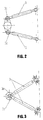
- eine erste Ausführungsform der zur Führung des Federzylinders vorgesehenen Lenker und
- Fig.3
- eine zweite Ausführungsform der zur Führung des Federzylinders vorgesehenen Lenker.
- Wie in Fig. 1 dargestellt, ist das Fahrzeugrad R, welches eine Radachse 13 besitzt, an einem Achsträger 7 gehalten und mit Hilfe eines Federzylinders sowie mit Hilfe von Querlenkern 3 geführt. Der Federzylinder umfaßt ein Innenrohr 1a und ein Außenrohr 1b. Innen- und Außenrohr sind verschieblich und verdrehbar zueinander angeordnet.
- Mittig durch den Federzylinder erstreckt sich eine Hydraulikölzuführung 6', welche im wesentlichen aus zwei konzentrischen Rohren besteht, welche so abgedichtet sind, daß sich die beiden Rohre in Längsrichtung zueinander verschieben und relativ zueinander verdrehen können. Ferner ist die Hydrauliköldurchführung 6' mit Öl-Ausgleichseinrichtungen (nicht dargestellt) versehen, um Volumenänderungen als Folge von Federbewegungen zu kompensieren.
- Die Hydraulikdurchführung 6' ist an eine Hydraulikölzuführung 6 angeschlossen. Die Hydrauliköldurchführung 6' steht in Strömungsverbindung mit einem Hydraulikmotor 2, der einen Einzelradantrieb darstellt und zusammen mit einem Schaltgetriebe 4 in dem Achsträger 7 aufgenommen ist. Der Achsträger 7 und damit auch der Hydraulikmotor 2 und das Schaltgetriebe 4 sind im Nabenbereich des Fahrzeugrades R, d.h., im Bereich der Radachse bzw. des Rad-Drehmittelpunktes 13 angeordnet.
- Das untere Ende des Federzylinder-Außenrohres 1b ist fest mit der Oberseite des Achsträgers 7 verbunden, während das obere Ende des Federzylinder-Innenrohres 1a räumlich beweglich bzw. dreidimensional beweglich in einem elastischen Lager 8 gelagert ist. Dieses elastische Lager 8, welches vorzugsweise als Gummilager ausgebildet ist, ist an einem Querholm 14 befestigt, welcher sich im wesentlichen parallel zur Radachse 13 erstreckt.
- Dieser Querholm 14 wird von einem Träger 9 gehalten, mit dessen oberem Ende der Querholm verbunden ist. Das untere Ende des Trägers 9 ist mit dem Fahrzeugrahmen 12 verschweißt.
- Wie in Fig. 1 dargestellt, ist der Fahrzeugrahmen 12 so tief angeordnet, daß er sich im wesentlichen auf der Höhe der Radachse 13, d.h. im wesentlichen auf der Höhe des Hydraulikmotors 2 befindet.
- Die beiden Querlenker 3 sind mit ihren dem Fahrzeugrad zugewandten Enden 3a an der Unterseite des Achsträgers 7 angelenkt, während die entgegengesetzten Enden der Querlenker 3 an der Unterseite des Fahrzeugrahmens 12 angelenkt sind.
- Gemäß der in Fig. 2 dargestellten Ausführungsform sind die Enden 3a der beiden Lenker im Abstand voneinander angelenkt. Gemäß der in Fig. 3 dargestellten Ausführungsform sind jedoch die Enden 3a der beiden Querlenker 3 miteinander verbunden.
- Die Querlenker 3 dienen zum Aufnehmen der im Fahrzeugbetrieb auftretenden Beschleunigungskräfte sowie Bremskräfte sowie ferner der Seitenführungskräfte und der resultierenden Stützkräfte aus der Aufstandskraft (bei Verwendung der erfindungsgemäßen Vorrichtung für Kranfahrzeuge). Vom Träger 9 sind als Folge der beiden Querlenker lediglich noch aufzunehmen die Aufstandskraft sowie die Restkräfte des Bremsens und Beschleunigens. Folglich ist durch die erfindungsgemäße Konstruktion der Träger 9 entlastet von all den Kräften, welche von den Querträgern aufgenommen werden. Dieses wiederum hat zur Folge, daß der Träger 9 konstruktiv recht einfach gestaltet werden kann, was zu einer Gewichtsersparnis führt.
- Wie ferner in Fig. 1 dargestellt, ist ein Lenkhebel 10 an dem Federzylinder-Außenrohr 1b befestigt, welches fest mit dem Achsträger 7 verbunden ist. An dem Lenkhebel 10 ist eine Spurstange 5 mit Hilfe eines ersten Kugelkopfes 11 räumlich, d.h. dreidimensional beweglich, gelagert. Ein zweiter Kugelkopf 11' ist am anderen Ende der Spurstange 5 vorgesehen und mit einer Einrichtung (nicht dargestellt) zum Lenken des Fahrzeugrades R verbunden.
- Im Bereich des Federzylinders 1a, 1b besteht die Hydrauliköldurchführung 6' aus einem mittig im Federzylinder-Innenrohr 1a vorgesehenen ersten Rohrabschnitt und einen mittig im Federzylinder-Außenrohr 1b vorgesehenen zweiten Rohrabschnitt. Diese beiden Abschnitte der Öldurchführung 6' weisen unterschiedliche Durchmesser auf, so daß die beiden Rohrabschnitte einander über eine gewisse Länge überlappend ineinandergesteckt sind. Gleichzeitig sind die beiden Rohrabschnitte gegeneinander abgedichtet, so daß Relativbewegungen des (federnden) Federzylinderaußenrohrs 1b relativ zum (zur gefederten Masse gehörigen) Federzylinder-Innenrohr 1a von den beiden Rohrleitungsabschnitten der Öldurchführung 6' mitgemacht werden können. Wie schon erwähnt, sind nicht dargestellte Ausgleichsbehälter oder dergleichen vorgesehen, um als Folge von Federungsbewegungen auftretende Volumenänderungen zu kompensieren.
Claims (5)
- Vorrichtung zum Antreiben, Führen und Lenken eines an einem Achsträger (7) gehaltenen Fahrzeugrades (R) für ein mit einem Rahmen (12) versehenes Fahrzeug,
gekennzeichnet durch- einen lenkergeführten Federzylinder, der ein Außenrohr (1b) und ein Innenrohr (1a) aufweist und von einer Hydrauliköldurchführung (6, 6') mittig durchsetzt ist,- einen mit der Hydrauliköldurchführung (6, 6') verbundenen Hydraulikmotor (2), der zusammen mit einem in dem Achsträger (7) aufgenommenen Schaltgetriebe (4) im Nabenbereich des Fahrzeugrades (R) angeordnet ist, wobei der Rahmen (12) des Fahrzeuges im wesentlichen auf die Höhe der Radachse (13) abgesenkt ist, und- wobei das untere Ende des Federzylinderaußenrohres (1b) fest mit dem Achsträger (7) verbunden und das obere Ende des Federzylinderinnenrohres (1a) räumlich beweglich in einem elastischen Lager (8) gelagert, welches an einem Querholm (14) befestigt ist, der sich über einen Träger (9) auf den Fahrzeugrahmen (12) abstützt. - Vorrichtung nach Anspruch 1, dadurch gekennzeichnet, daß zwei Querlenker (3) vorgesehen sind, deren dem Fahrzeugrad (R) zugewandte Enden (3a) an der Unterseite des Achsträgers (7) befestigt sind und deren entgegengesetzte Enden an der Unterseite des Fahrzeugrahmens (12) angelenkt sind.
- Vorrichtung nach Anspruch 2, dadurch gekennzeichnet, daß die dem Fahrzeugrad (R) zugewandten Enden (3a) der beiden Querlenker (3) miteinander verbunden sind.
- Vorrichtung nach einem der Ansprüche 1 bis 3, dadurch gekennzeichnet, daß an dem Federzylinderaußenrohr (1b) ein Lenkhebel (10) befestigt ist, an welchem eine Spurstange (5) mit eines Kugelkopfes (11) gelagert ist.
- Vorrichtung nach einem der Ansprüche 1 bis 4, dadurch gekennzeichnet, daß das Schaltgetriebe (4) zweistufig schaltbar ausgebildet ist.
Applications Claiming Priority (2)
| Application Number | Priority Date | Filing Date | Title |
|---|---|---|---|
| DE9305633U DE9305633U1 (de) | 1993-04-15 | 1993-04-15 | |
| DE9305633U | 1993-04-15 |
Publications (2)
| Publication Number | Publication Date |
|---|---|
| EP0620132A1 true EP0620132A1 (de) | 1994-10-19 |
| EP0620132B1 EP0620132B1 (de) | 1998-07-29 |
Family
ID=6892013
Family Applications (1)
| Application Number | Title | Priority Date | Filing Date |
|---|---|---|---|
| EP94105501A Expired - Lifetime EP0620132B1 (de) | 1993-04-15 | 1994-04-08 | Vorrichtung zum Antreiben, Führen und Lenken eines Fahrzeugrades |
Country Status (4)
| Country | Link |
|---|---|
| US (1) | US5542492A (de) |
| EP (1) | EP0620132B1 (de) |
| AT (1) | ATE168942T1 (de) |
| DE (2) | DE9305633U1 (de) |
Cited By (5)
| Publication number | Priority date | Publication date | Assignee | Title |
|---|---|---|---|---|
| WO2007118845A1 (de) * | 2006-04-13 | 2007-10-25 | Peter Seikel | Einzelradgetriebe |
| WO2013150099A3 (de) * | 2012-04-05 | 2013-12-12 | Goldhofer Ag | Schwerlastanhänger mit macpherson-einzelradaufhängung |
| FR3028459A1 (fr) * | 2014-11-18 | 2016-05-20 | Laurent Eugene Albert | Procede d'alimentation d'un moteur hydraulique et suspension a verin comprenant une chambre de compensation s'y rapportant |
| WO2019120734A1 (de) * | 2017-12-22 | 2019-06-27 | Manitowoc Crane Group France Sas | Mobilkran-fahrwerkachse |
| WO2021143978A1 (de) * | 2020-01-16 | 2021-07-22 | Schaeffler Technologies AG & Co. KG | Radmodul und federbein für ein kraftfahrzeug |
Families Citing this family (10)
| Publication number | Priority date | Publication date | Assignee | Title |
|---|---|---|---|---|
| DE4341034C2 (de) * | 1993-12-02 | 1997-03-13 | Glaeser Hydraulik Gmbh | Hydraulikleitung-Verbindung |
| US7533747B2 (en) * | 2000-01-26 | 2009-05-19 | E-Traction Europe B.V. | Wheel provided with driving means |
| NL1014182C2 (nl) * | 2000-01-26 | 2001-07-27 | Special Products For Industry | Wiel voorzien van aandrijfmiddelen. |
| BE1013399A3 (nl) * | 2000-04-20 | 2001-12-04 | Hool Nv Van | Verbeterde voorwielophanging voor bussen en dergelijke. |
| DE602004012825T2 (de) * | 2003-12-11 | 2009-05-20 | Kanzaki Kokyukoki Mfg. Co., Ltd., Amagasaki | Hydraulisches Achsgetriebe und Fahrzeug mit solchem Achsgetriebe |
| DE102004014555A1 (de) * | 2004-03-25 | 2005-12-22 | Zf Friedrichshafen Ag | Radaufhängung für ein lenkbares Fahrzeugrad |
| CN2889765Y (zh) * | 2006-03-03 | 2007-04-18 | 广州市番禺华南摩托企业集团有限公司 | 带有球头转向节的前摇架 |
| WO2008138346A1 (en) * | 2007-05-10 | 2008-11-20 | Aarhus Universitet | Omni rotational driving and steering wheel |
| JP6369166B2 (ja) * | 2014-06-27 | 2018-08-08 | 日産自動車株式会社 | 車両用サスペンション装置 |
| CN106470862B (zh) * | 2014-06-27 | 2018-10-30 | 日产自动车株式会社 | 轮毂电机车的簧下供电装置 |
Citations (4)
| Publication number | Priority date | Publication date | Assignee | Title |
|---|---|---|---|---|
| US3581682A (en) * | 1969-02-24 | 1971-06-01 | Aerospace America Inc | Driving apparatus for a wheeled vehicle |
| US3997018A (en) * | 1972-01-14 | 1976-12-14 | Hyster Company | Drive wheel assembly with high flotation tire for compaction vehicles |
| US5150763A (en) * | 1991-04-24 | 1992-09-29 | Aisin Aw Co., Ltd. | Wiring and piping arrangement for a vehicle motor |
| WO1993005969A1 (de) * | 1991-09-21 | 1993-04-01 | Krupp Industrietechnik Gesellschaft Mit Beschränkter Haftung | Federbein für hydraulischen radantrieb |
Family Cites Families (7)
| Publication number | Priority date | Publication date | Assignee | Title |
|---|---|---|---|---|
| DE1857359U (de) * | 1958-12-03 | 1962-08-23 | Ehrenreich & Cie A | Vorrichtung zur abstuetzung der radgelenke gelenkter fahrzeugraeder. |
| DE1120290B (de) * | 1959-01-14 | 1961-12-21 | Max Adolf Mueller Dipl Ing | Radaufhaengung fuer Fahrzeuge, insbesondere Schwerlastfahrzeuge |
| US3161246A (en) * | 1962-07-16 | 1964-12-15 | Product Dev Corp | Driving and suspension system for amphibious vehicle |
| DE2623757A1 (de) * | 1976-05-26 | 1977-12-01 | Trw Inc | Antriebseinheit |
| US4162713A (en) * | 1978-04-03 | 1979-07-31 | Otis Engineering Corporation | Planetary transmission with hydraulic engagement and disengagement |
| FR2432948A1 (fr) * | 1978-07-26 | 1980-03-07 | Iao Industrie Riunite Spa | Montant pour suspensions du type mac pherson pour vehicules automobiles |
| JP3367614B2 (ja) * | 1991-10-17 | 2003-01-14 | 株式会社小松製作所 | ダンプトラックの操舵輪油圧駆動装置 |
-
1993
- 1993-04-15 DE DE9305633U patent/DE9305633U1/de not_active Expired - Lifetime
-
1994
- 1994-04-08 AT AT94105501T patent/ATE168942T1/de not_active IP Right Cessation
- 1994-04-08 EP EP94105501A patent/EP0620132B1/de not_active Expired - Lifetime
- 1994-04-08 DE DE59406529T patent/DE59406529D1/de not_active Expired - Fee Related
- 1994-04-12 US US08/226,482 patent/US5542492A/en not_active Expired - Fee Related
Patent Citations (4)
| Publication number | Priority date | Publication date | Assignee | Title |
|---|---|---|---|---|
| US3581682A (en) * | 1969-02-24 | 1971-06-01 | Aerospace America Inc | Driving apparatus for a wheeled vehicle |
| US3997018A (en) * | 1972-01-14 | 1976-12-14 | Hyster Company | Drive wheel assembly with high flotation tire for compaction vehicles |
| US5150763A (en) * | 1991-04-24 | 1992-09-29 | Aisin Aw Co., Ltd. | Wiring and piping arrangement for a vehicle motor |
| WO1993005969A1 (de) * | 1991-09-21 | 1993-04-01 | Krupp Industrietechnik Gesellschaft Mit Beschränkter Haftung | Federbein für hydraulischen radantrieb |
Cited By (13)
| Publication number | Priority date | Publication date | Assignee | Title |
|---|---|---|---|---|
| EA015050B1 (ru) * | 2006-04-13 | 2011-04-29 | Петер Зайкель | Индивидуальный привод колеса |
| WO2007118845A1 (de) * | 2006-04-13 | 2007-10-25 | Peter Seikel | Einzelradgetriebe |
| RU2623366C2 (ru) * | 2012-04-05 | 2017-06-23 | Гольдхофер Аг | Большегрузный прицеп с независимой подвеской колёс мак-ферсона |
| WO2013150099A3 (de) * | 2012-04-05 | 2013-12-12 | Goldhofer Ag | Schwerlastanhänger mit macpherson-einzelradaufhängung |
| US9919573B2 (en) | 2012-04-05 | 2018-03-20 | Goldhofer Ag | Heavy-duty trailer with MacPherson independent wheel suspension |
| FR3028459A1 (fr) * | 2014-11-18 | 2016-05-20 | Laurent Eugene Albert | Procede d'alimentation d'un moteur hydraulique et suspension a verin comprenant une chambre de compensation s'y rapportant |
| WO2016078917A1 (fr) * | 2014-11-18 | 2016-05-26 | Albert Laurent Eugène | Procede pour alimenter en fluide hydraulique un moteur hydraulique de roue motrice, suspension a verin s'y rapportant et vehicule ainsi equipe |
| FR3028458A1 (fr) * | 2014-11-18 | 2016-05-20 | Laurent Eugene Albert | Procede pour alimenter en fluide hydraulique un moteur hydraulique de roue motrice, suspension a verin s'y rapportant et vehicule ainsi equipe |
| US10421331B2 (en) | 2014-11-18 | 2019-09-24 | Laurent Eugène ALBERT | Method of supplying a hydraulic motor for a drive wheel with hydraulic fluid, associated cylinder-type suspension system and vehicle equipped therewith |
| WO2019120734A1 (de) * | 2017-12-22 | 2019-06-27 | Manitowoc Crane Group France Sas | Mobilkran-fahrwerkachse |
| US11919359B2 (en) | 2017-12-22 | 2024-03-05 | Manitowoc Crane Group France Sas | Mobile crane travel gear axle |
| DE102017131165B4 (de) | 2017-12-22 | 2024-04-11 | Manitowoc Crane Group France Sas | Mobilkran-Fahrwerk |
| WO2021143978A1 (de) * | 2020-01-16 | 2021-07-22 | Schaeffler Technologies AG & Co. KG | Radmodul und federbein für ein kraftfahrzeug |
Also Published As
| Publication number | Publication date |
|---|---|
| DE59406529D1 (de) | 1998-09-03 |
| ATE168942T1 (de) | 1998-08-15 |
| EP0620132B1 (de) | 1998-07-29 |
| US5542492A (en) | 1996-08-06 |
| DE9305633U1 (de) | 1993-06-17 |
Similar Documents
| Publication | Publication Date | Title |
|---|---|---|
| EP0620132B1 (de) | Vorrichtung zum Antreiben, Führen und Lenken eines Fahrzeugrades | |
| EP0278095B1 (de) | Radaufhängung für lenkbare Räder von Kraftfahrzeugen, insbesondere für Hinterräder | |
| EP0656270A1 (de) | Radaufhängung | |
| DE102017106826A1 (de) | Federbein für ein Kraftfahrzeug | |
| EP0141093A2 (de) | Radaufhängung für lenkbare Vorderräder von Kraftfahrzeugen | |
| DE3743203C2 (de) | ||
| EP0464412B1 (de) | Luftgefederte Kurbelachse | |
| DE3535589C1 (de) | Radaufhaengung fuer absenkbare Fahrzeugaufbauten,insbesondere fuer Anhaenger,frontangetriebene LKW(Bus-Kombi),Wohnmobile | |
| EP0806310A2 (de) | Einzelradaufhängung für ein luftgefedertes, lenkbares Rad eines Omnibusses oder Lastkraftwagens | |
| EP0247389B1 (de) | Radführungsschwinge für horizontal schwenkbare Schienenräder mit aussen liegendem Antrieb | |
| DE3809995A1 (de) | Hintere aufhaengungseinrichtung fuer motorfahrzeuge | |
| DE3807273C1 (de) | ||
| DE102016207631A1 (de) | Einzelradaufhängung eines Fahrzeugs mit einem radführenden Blattfederelement aus einem Faserverbund-Werkstoff | |
| DE3049198C2 (de) | ||
| WO1994029133A1 (de) | Aufhängung für ein fahrzeugrad | |
| DE4024825C1 (en) | Support legs for semi-trailer - has inner tube sections with supports for feet which pivot | |
| DE102010060274A1 (de) | Achsaggregate | |
| DE1530880A1 (de) | Lenkvorrichtung fuer ein Mehrachsaggregat | |
| DE3234475C2 (de) | ||
| DD152513A5 (de) | Achsanlenkung fuer eine angetriebene achse eines strassenfahrzeugs | |
| DE1004497B (de) | Als Pendelachse ausgebildete Hinterachse fuer Motorfahrzeuge | |
| DE102021104230B4 (de) | Radmodul | |
| WO2005051687A1 (de) | Einzelradaufhängung für ein insbesondere nicht gelenktes kfz-rad | |
| DE102010060273A1 (de) | Gewichtsoptimierte Lastkraftfahrzeuge | |
| WO2023193983A1 (de) | Nutzfahrzeug |
Legal Events
| Date | Code | Title | Description |
|---|---|---|---|
| PUAI | Public reference made under article 153(3) epc to a published international application that has entered the european phase |
Free format text: ORIGINAL CODE: 0009012 |
|
| AK | Designated contracting states |
Kind code of ref document: A1 Designated state(s): AT BE CH DE DK ES FR GB IT LI LU MC NL PT SE |
|
| 17P | Request for examination filed |
Effective date: 19941228 |
|
| 17Q | First examination report despatched |
Effective date: 19961111 |
|
| GRAG | Despatch of communication of intention to grant |
Free format text: ORIGINAL CODE: EPIDOS AGRA |
|
| RAP1 | Party data changed (applicant data changed or rights of an application transferred) |
Owner name: KASPAR, ERNST Owner name: LUTZ, FRANZ Owner name: COMPACT TRUCK AG |
|
| GRAG | Despatch of communication of intention to grant |
Free format text: ORIGINAL CODE: EPIDOS AGRA |
|
| GRAH | Despatch of communication of intention to grant a patent |
Free format text: ORIGINAL CODE: EPIDOS IGRA |
|
| GRAH | Despatch of communication of intention to grant a patent |
Free format text: ORIGINAL CODE: EPIDOS IGRA |
|
| GRAA | (expected) grant |
Free format text: ORIGINAL CODE: 0009210 |
|
| AK | Designated contracting states |
Kind code of ref document: B1 Designated state(s): AT BE CH DE DK ES FR GB IT LI LU MC NL PT SE |
|
| PG25 | Lapsed in a contracting state [announced via postgrant information from national office to epo] |
Ref country code: NL Free format text: LAPSE BECAUSE OF FAILURE TO SUBMIT A TRANSLATION OF THE DESCRIPTION OR TO PAY THE FEE WITHIN THE PRESCRIBED TIME-LIMIT Effective date: 19980729 Ref country code: IT Free format text: LAPSE BECAUSE OF FAILURE TO SUBMIT A TRANSLATION OF THE DESCRIPTION OR TO PAY THE FEE WITHIN THE PRESCRIBED TIME-LIMIT;WARNING: LAPSES OF ITALIAN PATENTS WITH EFFECTIVE DATE BEFORE 2007 MAY HAVE OCCURRED AT ANY TIME BEFORE 2007. THE CORRECT EFFECTIVE DATE MAY BE DIFFERENT FROM THE ONE RECORDED. Effective date: 19980729 Ref country code: GB Free format text: LAPSE BECAUSE OF FAILURE TO SUBMIT A TRANSLATION OF THE DESCRIPTION OR TO PAY THE FEE WITHIN THE PRESCRIBED TIME-LIMIT Effective date: 19980729 Ref country code: FR Free format text: LAPSE BECAUSE OF FAILURE TO SUBMIT A TRANSLATION OF THE DESCRIPTION OR TO PAY THE FEE WITHIN THE PRESCRIBED TIME-LIMIT Effective date: 19980729 Ref country code: ES Free format text: THE PATENT HAS BEEN ANNULLED BY A DECISION OF A NATIONAL AUTHORITY Effective date: 19980729 |
|
| REF | Corresponds to: |
Ref document number: 168942 Country of ref document: AT Date of ref document: 19980815 Kind code of ref document: T |
|
| REG | Reference to a national code |
Ref country code: CH Ref legal event code: EP |
|
| REF | Corresponds to: |
Ref document number: 59406529 Country of ref document: DE Date of ref document: 19980903 |
|
| PG25 | Lapsed in a contracting state [announced via postgrant information from national office to epo] |
Ref country code: SE Free format text: LAPSE BECAUSE OF FAILURE TO SUBMIT A TRANSLATION OF THE DESCRIPTION OR TO PAY THE FEE WITHIN THE PRESCRIBED TIME-LIMIT Effective date: 19981029 Ref country code: PT Free format text: LAPSE BECAUSE OF FAILURE TO SUBMIT A TRANSLATION OF THE DESCRIPTION OR TO PAY THE FEE WITHIN THE PRESCRIBED TIME-LIMIT Effective date: 19981029 Ref country code: DK Free format text: LAPSE BECAUSE OF FAILURE TO SUBMIT A TRANSLATION OF THE DESCRIPTION OR TO PAY THE FEE WITHIN THE PRESCRIBED TIME-LIMIT Effective date: 19981029 |
|
| EN | Fr: translation not filed | ||
| NLV1 | Nl: lapsed or annulled due to failure to fulfill the requirements of art. 29p and 29m of the patents act | ||
| GBV | Gb: ep patent (uk) treated as always having been void in accordance with gb section 77(7)/1977 [no translation filed] |
Effective date: 19980729 |
|
| PG25 | Lapsed in a contracting state [announced via postgrant information from national office to epo] |
Ref country code: LU Free format text: LAPSE BECAUSE OF NON-PAYMENT OF DUE FEES Effective date: 19990408 Ref country code: AT Free format text: LAPSE BECAUSE OF NON-PAYMENT OF DUE FEES Effective date: 19990408 |
|
| PG25 | Lapsed in a contracting state [announced via postgrant information from national office to epo] |
Ref country code: LI Free format text: LAPSE BECAUSE OF NON-PAYMENT OF DUE FEES Effective date: 19990430 Ref country code: CH Free format text: LAPSE BECAUSE OF NON-PAYMENT OF DUE FEES Effective date: 19990430 Ref country code: BE Free format text: LAPSE BECAUSE OF NON-PAYMENT OF DUE FEES Effective date: 19990430 |
|
| PLBE | No opposition filed within time limit |
Free format text: ORIGINAL CODE: 0009261 |
|
| STAA | Information on the status of an ep patent application or granted ep patent |
Free format text: STATUS: NO OPPOSITION FILED WITHIN TIME LIMIT |
|
| 26N | No opposition filed | ||
| BERE | Be: lapsed |
Owner name: KASPAR ERNST Effective date: 19990430 Owner name: LUTZ FRANZ Effective date: 19990430 Owner name: COMPACT TRUCK A.G. Effective date: 19990430 |
|
| PG25 | Lapsed in a contracting state [announced via postgrant information from national office to epo] |
Ref country code: MC Free format text: LAPSE BECAUSE OF NON-PAYMENT OF DUE FEES Effective date: 19991031 |
|
| REG | Reference to a national code |
Ref country code: CH Ref legal event code: PL |
|
| PGFP | Annual fee paid to national office [announced via postgrant information from national office to epo] |
Ref country code: DE Payment date: 20030528 Year of fee payment: 10 |
|
| PG25 | Lapsed in a contracting state [announced via postgrant information from national office to epo] |
Ref country code: DE Free format text: LAPSE BECAUSE OF NON-PAYMENT OF DUE FEES Effective date: 20041103 |