EP0616967B1 - Bobinoir automatique avec plusieurs boucles de transport pour bobines textiles, qui comportent des chemins de transport partiellement communs - Google Patents
Bobinoir automatique avec plusieurs boucles de transport pour bobines textiles, qui comportent des chemins de transport partiellement communs Download PDFInfo
- Publication number
- EP0616967B1 EP0616967B1 EP94100287A EP94100287A EP0616967B1 EP 0616967 B1 EP0616967 B1 EP 0616967B1 EP 94100287 A EP94100287 A EP 94100287A EP 94100287 A EP94100287 A EP 94100287A EP 0616967 B1 EP0616967 B1 EP 0616967B1
- Authority
- EP
- European Patent Office
- Prior art keywords
- preparation
- automatic winder
- stations
- control means
- reading
- Prior art date
- Legal status (The legal status is an assumption and is not a legal conclusion. Google has not performed a legal analysis and makes no representation as to the accuracy of the status listed.)
- Expired - Lifetime
Links
Images
Classifications
-
- B—PERFORMING OPERATIONS; TRANSPORTING
- B65—CONVEYING; PACKING; STORING; HANDLING THIN OR FILAMENTARY MATERIAL
- B65H—HANDLING THIN OR FILAMENTARY MATERIAL, e.g. SHEETS, WEBS, CABLES
- B65H67/00—Replacing or removing cores, receptacles, or completed packages at paying-out, winding, or depositing stations
- B65H67/06—Supplying cores, receptacles, or packages to, or transporting from, winding or depositing stations
- B65H67/063—Marking or identifying devices for packages
-
- B—PERFORMING OPERATIONS; TRANSPORTING
- B65—CONVEYING; PACKING; STORING; HANDLING THIN OR FILAMENTARY MATERIAL
- B65H—HANDLING THIN OR FILAMENTARY MATERIAL, e.g. SHEETS, WEBS, CABLES
- B65H2701/00—Handled material; Storage means
- B65H2701/30—Handled filamentary material
- B65H2701/31—Textiles threads or artificial strands of filaments
Definitions
- the invention relates to an automatic winding machine with the features of the preamble of claim 1.
- a generic winder is known from DE 39 19 542 A1.
- the transport system of this winding machine also has a secondary transport path via which textile bobbins that have not been fully unwound are fed back from a return path of the feed path.
- a first preparation device is arranged on this secondary transport path, which is specially equipped for thread search on residual bobbins.
- a complete preparation is carried out on this preparation device, that is to say that after the thread search, the thread start is deposited at a defined point in such a way that it can be easily grasped in the winding unit and fed to the thread connecting members.
- a second preparation device is arranged on the feed path and is particularly suitable for preparing full textile bobbins.
- the thread start is first searched for and loosened in the area of the cop's foot, while the main component of this preparation device is a so-called jacket preparation, which searches for the thread start on the main winding body.
- the second preparation device the beginning of the thread can neither be found on the cops foot nor on the main winding body, since it is deposited either in the form of top turns on the sleeve tip or in the sleeve.
- preparation of the textile bobbins at the second preparation device is only carried out if the textile bobbins have not yet been prepared.
- completely prepared textile bobbins are no longer treated in the second preparation device in the first preparation device. Rather, you can run through this second preparation device undisturbed. This prevents the effectiveness of the preparation from being reduced due to the failure of a preparation attempt on a textile bobbin prepared as such.
- an immediately following textile bobbin can get into the preparation device more quickly.
- the second preparation device which, as already explained, is passed through by all textile bobbins fed to the winder, must ensure a high cycle performance.
- the thread search is not limited to a specific area. In most cases, before searching for the beginning of the thread on the main winding body of the textile bobbin, loops in the area of the core of the tube have to be released. If necessary, a relatively steep rear turn leading to the foot turns must also be solved. Therefore, in most cases, this second preparation device consists of several individual stations to which separate tasks are assigned. Since within the scope of this invention, thread search measures are no longer to be carried out on textile bobbins that have already been prepared, the control must extend to all stations based on the information read about the preparation that has taken place. This can be done by coupling a reading device to the control means for the commissioning of each of the stations, by an information connection between these control devices or by reading devices available at each station.
- the second preparatory device is also provided with monitoring means for monitoring the preparatory success in this preparatory device, care must be taken to ensure that in the case of textile bobbins that are completely prepared from the first preparatory device, this monitoring device receives a signal which sets it in the state which she achieves with a positive result of her own review. This avoids classifying these textile bobbins as unprepared and preventing them from being fed to the winder.
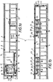
- Textile bobbins in the form of cops are transported in a winder 1.
- the winder 1 has a bobbin and tube transport system with several transport loops, some of which have common transport paths.
- Caddies 4 which carry the cops or sleeves, are transported on these transport routes. The depiction of the cops or sleeves has been omitted for reasons of clarity.
- a feed path 2 for feeding the cops to the winding units extends along the entire winding machine.
- Preparation lines 25 branch off from the feed path 2 and lead through second preparation devices formed from preparation stations 26 to 28. These preparation stations 26 to 28 allow the cops to be prepared step by step in a known manner, as is described, for example, in DE 39 19 542 A1.
- a distribution section 24 is provided which alternatively feeds the cops to a so-called reversing belt 3 or again to the feed path 2.
- This distribution section 24 is controlled by the last preparation station 28, which has monitoring means for monitoring the Has preparatory success. If the cop is successfully prepared, the distribution section 24, which here also consists of a reversing belt, feeds it to the reversing belt 3 already mentioned.
- the caddy 4 carrying it is fed to the feed path 2, which either leads it to the next preparation path 25 or around the end of the winding machine 1 via the diversion path 31 to a return belt 22.
- This return belt 22 runs parallel to the feed belt 2, likewise along the entire winding machine 1. The distribution of the cops on the different preparation lines 25 is described further below.
- the reversing belt 3 is switched in its transport direction at predeterminable time intervals and distributes the supplied cops to the transport paths 21 leading through the winding stations 5. Between the respective winding station 5, that is to say the unwinding position of the respective cop, and the reversing belt 3 there are still two reserve positions 6 for the caddies 4 wearing the heads. On the reversing belt 3, groups 7 of caddies 4 patrol with cops, which then enter a transport path 21 leading through the winding stations 5 when the rearmost reserve position 6 is not occupied. Details can also be found in DE 39 19 542 A1. It should also be pointed out that only a small part of the rotating caddies 4 has been shown for reasons of clarity. In particular, the transport tracks 21 should in most cases be occupied by three caddies 4, as is demonstrated on a transport track 21.
- This residual cop 9 is a so-called residual cop, which still carries a quantity of remaining thread that can be processed.
- This residual cop 9 is located next to a residual thread detector 33, which detects the thread quantity still present.
- This residual thread detector controls an electromagnet 11, which acts on an iron ring present on the caddies 4 and redirects the caddy from the return belt 22 to a secondary transport path 12.
- the remaining cop arrives at a first preparation device, a cone preparation device 14, which searches for the thread start on the cop cone regardless of its position and deposits it again in such a way that it can later be detected at the winding point.
- This cone preparation device 14 accordingly carries out a complete preparation of the cop.
- a cop prepared in this way is then fed back to the feed path 2 via a connecting section 16.
- the cone preparation device 14 also has monitoring means for monitoring the preparation success, a thread sensor 15 will.
- a successful preparation, recognized by the thread sensor 15, is transmitted to a writing device 37, which confirms the successful preparation by writing it into a memory chip attached to the caddy 4.
- the arrangement of a memory chip on the caddy including the means for wireless data exchange can be found, for example, in DE 40 41 713 A1, while the practical implementation of the data exchange is described, for example, in DE 40 38 970 A1.
- a sleeve with a small amount of remaining thread transported alongside an end frame 19 is also identified as such by the remaining thread detector 33 and the caddy 4 carrying it is redirected by the electromagnet 11 into the secondary transport path 12.
- this sleeve 8 is immediately branched off again and arrives at a sleeve cleaning device 10.
- An electromagnet can also be arranged at this branch, which is additionally controlled by the residual thread detector 33. A representation has been omitted for reasons of space.
- the cleaned sleeve 8 then returns to the return path 22 via the intersection 20 or, after unsuccessful cleaning, into the storage path 18 (see also DE 39 19 542 A1).
- a completely empty spool 36 ejected from a winding unit 5 is also fed to the residual thread detector 33 on the return path 22, which does not switch on the electromagnet 11 in this case, so that the caddy 4 carrying the empty tube 36 arrives on the transport path 13, on which the empty tube is exchanged for a fresh cop coming from the spinning machine.
- This cop then returns to the feed path 2 and, in the manner described, to its unwinding position in the winding machine.
- Sensors 29 which cooperate with switches 30 are arranged on the respective branches from the feed path 2 into the preparation lines 25. These switches 30 are intended to distribute the cops over the preparation lines. If, for example, as shown in the drawing, there are two preparation lines 25, the switch 30 arranged on the first branch in the feed direction of the cops would alternately allow every second cop to pass, which is then on the feed path 2 to the next preparation line 25 (direction arrow 23 ) transported on becomes. It is of course also possible to switch over after two or more cops.
- the reading device 38 If a cop whose caddy 4 carries information of successful preparation in the first preparation device, the cone preparation 14, written in its memory chip, reaches the downstream first preparation section 25, this information is read by the reading device 38.
- This reading device 38 transmits this information to control means 26 ′ arranged at the preparation station 26.
- these control means which control the commissioning of this station 26, in particular a stop and drive device, such as is shown and described in DE 39 25 861 A1, prevent commissioning. This allows the caddy 4 to pass freely through the preparation station 26.
- control means 27 'and 28' also present in the subsequent preparation stations 27 and 28 are controlled in this case by the control means arranged upstream in each case in such a way that they allow the already prepared cop to pass through in the same way.
- the control device 28 also transmits the information of the preparation that has already been carried out to the monitoring device, a thread sensor 32, which is arranged in the preparation station 28. This thread sensor 32 then, just as when successful preparation is recognized in the preparation station 28, controls the distribution section 24 in such a way that the cop is fed to the reversing section 3.
- a read device 39 is arranged on the downstream preparation section 25, which controls the control means 26 ′′, 27 ′′ and 28 ′′ directly, but with a staggered time delay.
- the preparation station 28 Existing monitoring device in the form of a thread sensor 32 'controlled analogously to the thread sensor 32.
Landscapes
- Replacing, Conveying, And Pick-Finding For Filamentary Materials (AREA)
Claims (8)
- Bobinoir automatique (1), comprenant plusieurs boucles de transport qui sont destinées à des bobines textiles, qui présentent des trajets de transport partiellement communs et sur lesquelles sont disposés des premier (14) et deuxièmes (26 à 28) dispositifs de préparation dont la fonction et le mode de travail diffèrent et qui réalisent chacun une préparation complète pour des bobines textiles renvoyées depuis le bobinoir ou devant être amenées au bobinoir, respectivement, cependant qu'il est prévu, sur le premier dispositif de préparation (14) destiné aux bobines textiles renvoyées, des moyens de surveillance (15) pour surveiller le succès de la préparation,
caractérisé par le fait que :- à la bobine textile respective est associée, d'une manière connue en elle-même, une puce à mémoire électronique qui peut être chargée ou codée, respectivement, qui peut être effacée et qui sert de support aux informations sur le produit,- les moyens de surveillance (15) sont accouplés à un dispositif d'enregistrement (37) pour enregistrer le succès de la préparation dans la puce à mémoire,- au moins un dispositif de lecture (38, 39) est prévu sur le deuxième dispositif de préparation (26 à 28) destiné aux bobines textiles à amener au bobinoir, en vue de lire l'information qui est enregistrée comme identification du succès de la préparation, et :- le dispositif de lecture (38, 39) est accouplé à des moyens de commande (26' à 28', 26'' à 28'') pour la mise en marche du deuxième dispositif de préparation (26 à 28) lorsque l'information qui identifie le succès de la préparation n'est pas présente. - Bobinoir automatique selon la revendication 1, caractérisé par le fait que le deuxième dispositif de préparation est constitué par plusieurs postes disposés les uns derrière les autres (26 à 28), par le fait que le dispositif de lecture (38) est disposé dans la région du premier poste en aval (26), par le fait que le dispositif de lecture est accouplé à des moyens de commande (26') destinés à la mise en marche du premier poste, et par le fait qu'il existe entre les moyens de commande (26' à 28') des postes une liaison de commande qui produit une commande séquentielle à chaque fois du même genre pour les moyens de commande situés en aval.
- Bobinoir automatique selon la revendication 1, caractérisé par le fait que le deuxième dispositif de préparation est constitué par plusieurs postes disposés les uns derrière les autres (26 à 28), par le fait que le dispositif de lecture (39) est disposé dans la région du premier poste en aval (26), et par le fait que le dispositif de lecture est accouplé à des moyens de commande (26'' à 28'') destinés à la mise en marche de chacun des postes.
- Bobinoir automatique selon la revendication 1, caractérisé par le fait que le deuxième dispositif de préparation est constitué par plusieurs postes disposés les uns derrière les autres (26 à 28), par le fait que des dispositifs de lecture sont disposés dans la région de chacun des postes, et par le fait que les dispositifs de lecture sont accouplés aux moyens de commande respectifs (26'' à 28'') qui sont destinés à la mise en marche de chacun des postes.
- Bobinoir automatique selon l'une des revendications 1 à 4, caractérisé par le fait que le deuxième dispositif de préparation présente, pour surveiller le succès de la préparation, des moyens de surveillance (32, 32') qui comportent une liaison de transfert des informations, du moins indirecte, avec le dispositif de lecture (38, 39), l'information lue pouvant être transmise grâce à cette liaison aux moyens de surveillance par l'intermédiaire de la préparation qui a déjà été couronnée de succès.
- Bobinoir automatique selon l'une des revendications 1 à 5, caractérisé par le fait que, lorsque l'on utilise plusieurs deuxièmes dispositifs de préparation autonomes (26 à 28), il existe sur chacun de ces dispositifs de préparation un dispositif de lecture (38, 39) qui est accouplé aux moyens de commande destinés à la mise en marche du dispositif de préparation respectif.
- Bobinoir automatique selon l'une des revendications 1 à 6, caractérisé par le fait que les bobines textiles sont enfoncées verticalement sur des mandrins de supports individuels (4), et que les supports individuels sont posés sur des bandes transporteuses qui forment les trajets de transport du bobinoir (1) et par lesquelles ils peuvent être entraînés par frottement.
- Bobinoir automatique selon la revendication 7, caractérisé par le fait que les puces à mémoire électroniques sont posées sur les supports individuels (4).
Applications Claiming Priority (2)
| Application Number | Priority Date | Filing Date | Title |
|---|---|---|---|
| DE4309582 | 1993-03-24 | ||
| DE4309582A DE4309582A1 (de) | 1993-03-24 | 1993-03-24 | Automatische Spulmaschine, die mehrere, teilweise gemeinsame Transportwege aufweisende Transportschleifen für Textilspulen besitzt |
Publications (3)
| Publication Number | Publication Date |
|---|---|
| EP0616967A2 EP0616967A2 (fr) | 1994-09-28 |
| EP0616967A3 EP0616967A3 (en) | 1996-01-17 |
| EP0616967B1 true EP0616967B1 (fr) | 1997-05-02 |
Family
ID=6483741
Family Applications (1)
| Application Number | Title | Priority Date | Filing Date |
|---|---|---|---|
| EP94100287A Expired - Lifetime EP0616967B1 (fr) | 1993-03-24 | 1994-01-11 | Bobinoir automatique avec plusieurs boucles de transport pour bobines textiles, qui comportent des chemins de transport partiellement communs |
Country Status (5)
| Country | Link |
|---|---|
| US (1) | US5497952A (fr) |
| EP (1) | EP0616967B1 (fr) |
| JP (1) | JP4005149B2 (fr) |
| CN (1) | CN1070454C (fr) |
| DE (2) | DE4309582A1 (fr) |
Families Citing this family (22)
| Publication number | Priority date | Publication date | Assignee | Title |
|---|---|---|---|---|
| DE19518275B4 (de) * | 1995-05-18 | 2004-02-19 | Saurer Gmbh & Co. Kg | Verfahren zum Betreiben eines Transportsystems einer automatischen Spulmaschine und Transportsystem |
| KR0165741B1 (ko) * | 1996-02-28 | 1999-01-15 | 김경백 | 권사기 상의 콥의 정방 스핀들 위치 인식 및 데이터 관리시스템과 이송구간별 콥번호 트레이스 방법 |
| IT1283270B1 (it) * | 1996-03-18 | 1998-04-16 | Savio Macchine Tessili Spa | Procedimento e dispositivo di roccatura contemporanea di una pluralita di partite di filato |
| DE19636661A1 (de) * | 1996-09-10 | 1998-03-12 | Schlafhorst & Co W | Transportsystem für eine Textilmaschine |
| DE19650934B4 (de) * | 1996-12-07 | 2010-04-01 | Oerlikon Textile Gmbh & Co. Kg | Kopsvorbereitungseinrichtung einer Spulmaschine |
| DE29719432U1 (de) * | 1997-11-03 | 1998-03-26 | Wibmer Gmbh U Co Kg Papier For | Spul-Manschette mit Transponder, insbesondere zum Spinnspulen von Glasfasern |
| DE19802653A1 (de) * | 1998-01-24 | 1999-07-29 | Schlafhorst & Co W | Zentrifugenspinn-/Spulmaschine |
| CN101198534B (zh) * | 2005-06-15 | 2010-09-15 | 村田机械株式会社 | 络筒卷装的卷取管及络筒卷装的管理装置 |
| JP2008134694A (ja) * | 2006-11-27 | 2008-06-12 | Philtech Inc | Rfパウダーの付加方法およびrfパウダー付加基体シート |
| JP2008135446A (ja) * | 2006-11-27 | 2008-06-12 | Philtech Inc | Rfパウダーの製造方法 |
| JP2008134695A (ja) * | 2006-11-27 | 2008-06-12 | Philtech Inc | 基体データ管理システム |
| JP2008135951A (ja) * | 2006-11-28 | 2008-06-12 | Philtech Inc | Rfパウダー粒子、rfパウダー、およびrfパウダー含有基体 |
| JP2008134815A (ja) * | 2006-11-28 | 2008-06-12 | Philtech Inc | Rfパウダーの提供方法およびrfパウダー含有液 |
| JP2008134816A (ja) * | 2006-11-28 | 2008-06-12 | Philtech Inc | Rfパウダー粒子、rfパウダー、およびrfパウダーの励起方法 |
| JP2008136019A (ja) * | 2006-11-29 | 2008-06-12 | Philtech Inc | 磁界結合装置および読取り装置 |
| WO2008081699A1 (fr) * | 2006-12-28 | 2008-07-10 | Philtech Inc. | Plaque de base |
| US9140407B2 (en) | 2010-11-29 | 2015-09-22 | Lincoln Industrial Corporation | Pump having stirrer and direct feed |
| JP2015024870A (ja) * | 2013-07-24 | 2015-02-05 | 村田機械株式会社 | 繊維機械及び繊維機械のユニット固有値処理方法 |
| EP3802390A1 (fr) * | 2018-05-28 | 2021-04-14 | Oerlikon Textile GmbH & Co. KG | Procédé et dispositif de filage par fusion et d'enroulement de plusieurs fils |
| DE102018118942A1 (de) * | 2018-08-03 | 2020-02-06 | Maschinenfabrik Rieter Ag | Verfahren zur Herstellung von Kreuzspulen an einer Vielzahl in Längsrichtung einer Textilmaschine nebeneinander angeordneter Arbeitsstellen sowie Textilmaschine zur Herstellung von Kreuzspulen |
| IT202000018940A1 (it) * | 2020-08-03 | 2022-02-03 | Savio Macch Tessili Spa | Metodo di rilevazione presenza e/o tracciamento di un piattello porta-spola in una roccatrice o filatoio ad anello, piattello porta-spola per macchina roccatrice o filatoio ad anello e apparato di rilevazione presenza e/o tracciamento di una spola in una macchina roccatrice o filatoio ad anello |
| DE102021107062A1 (de) | 2021-03-22 | 2022-09-22 | Saurer Spinning Solutions Gmbh & Co. Kg | Spinnkops- und Hülsentransportsystem für eine automatische Spulmaschine |
Family Cites Families (12)
| Publication number | Priority date | Publication date | Assignee | Title |
|---|---|---|---|---|
| DE3732367A1 (de) * | 1987-05-16 | 1988-11-24 | Schlafhorst & Co W | Verfahren und vorrichtung zum vorbereiten eines nachfolgenden behandlungsvorgangs an einer textilspule |
| IT1229538B (it) * | 1988-01-25 | 1991-09-04 | Murata Machinery Ltd | Metodo di conduzione di un filatoio e di rivelazione di bobine difettose |
| DE3912030A1 (de) * | 1989-04-12 | 1990-10-25 | Zinser Textilmaschinen Gmbh | Verfahren und vorrichtung zum zuordnen qualitaetsbezogener daten auf mit kopsen bestueckten spulentraegern in einem maschinensystem |
| DE3919542A1 (de) * | 1989-06-15 | 1990-12-20 | Schlafhorst & Co W | Automatische spulmaschine mit einem kops- und huelsentransportsystem mit mehreren transportschleifen |
| JPH0676177B2 (ja) * | 1989-07-26 | 1994-09-28 | 村田機械株式会社 | トレイ搬送システム |
| DE3925861A1 (de) * | 1989-08-04 | 1991-02-07 | Schlafhorst & Co W | Kopsvorbereitungseinrichtung zum aufwinden des fadenanfanges auf der huelsenspitze des kopses |
| DE4025003A1 (de) * | 1990-08-07 | 1992-02-13 | Schlafhorst & Co W | Kopsvorbereitungseinrichtung mit durch sensorsignale gesteuert vertikal lageveraenderbaren mitteln zum ansaugen des fadenanfanges von der kegeligen bewicklungsoberflaeche von kopsen |
| DE4029894A1 (de) * | 1990-09-21 | 1992-03-26 | Schlafhorst & Co W | Spulmaschine, die von hand mit ablaufspulen beschickt werden kann |
| DE4038970A1 (de) * | 1990-12-06 | 1992-06-11 | Schlafhorst & Co W | Verfahren und einrichtung zur bidirektionalen datenuebermittlung zwischen einer textilmaschine und einem textilen produkt |
| DE4041713C2 (de) * | 1990-12-24 | 2000-05-31 | Schlafhorst & Co W | Transportpalette |
| US5269478A (en) * | 1991-05-23 | 1993-12-14 | Murata Kikai Kabushiki Kaisha | Bobbin trace system |
| DE4211112C2 (de) * | 1992-04-03 | 2002-02-14 | Schlafhorst & Co W | Vorrichtung zum Beliefern eines Spulautomaten mit aufrechtstehend auf Spulentransportteller aufgesteckten Kopsen |
-
1993
- 1993-03-24 DE DE4309582A patent/DE4309582A1/de not_active Withdrawn
-
1994
- 1994-01-11 DE DE59402582T patent/DE59402582D1/de not_active Expired - Fee Related
- 1994-01-11 EP EP94100287A patent/EP0616967B1/fr not_active Expired - Lifetime
- 1994-03-14 US US08/213,495 patent/US5497952A/en not_active Expired - Fee Related
- 1994-03-23 CN CN94103960A patent/CN1070454C/zh not_active Expired - Fee Related
- 1994-03-24 JP JP05400394A patent/JP4005149B2/ja not_active Expired - Fee Related
Also Published As
| Publication number | Publication date |
|---|---|
| CN1070454C (zh) | 2001-09-05 |
| DE59402582D1 (de) | 1997-06-05 |
| JP4005149B2 (ja) | 2007-11-07 |
| EP0616967A2 (fr) | 1994-09-28 |
| DE4309582A1 (de) | 1994-09-29 |
| US5497952A (en) | 1996-03-12 |
| JPH06305641A (ja) | 1994-11-01 |
| CN1096270A (zh) | 1994-12-14 |
| EP0616967A3 (en) | 1996-01-17 |
Similar Documents
| Publication | Publication Date | Title |
|---|---|---|
| EP0616967B1 (fr) | Bobinoir automatique avec plusieurs boucles de transport pour bobines textiles, qui comportent des chemins de transport partiellement communs | |
| DE3326000C2 (fr) | ||
| DE3308171A1 (de) | Kopstransportsystem fuer einen spulautomaten | |
| DE3434576C2 (fr) | ||
| DE3448249C2 (fr) | ||
| EP0548512B1 (fr) | Dispositif accumulateur d'un bobinoir pour supports individuels | |
| DE4209203B4 (de) | Spinn-/Spulmaschinenkombination mit einer Vorrichtung zum Überwachen des ordnungsgemäßen Arbeitens der einzelnen Spinnstellen | |
| DE4317266C2 (de) | Verfahren zum Steuern der Zuführung von Spinnspulen zu einer Spulmaschine | |
| DE3817405A1 (de) | Verfahren und vorrichtung zum spulenwechseln | |
| DE4209219B4 (de) | Spulmaschine mit einem geschlossenen Transportsystem für Spulentransportteller | |
| DE19905856B4 (de) | Hülsenliefereinrichtung für eine Kreuzspulen herstellende Textilmaschine | |
| DE4233819C2 (de) | Verfahren zum Betreiben einer automatischen Spulmaschine bei Partiewechsel | |
| EP0534229B1 (fr) | Procédé pour actionner un bobinoir automatique | |
| DE4211112C2 (de) | Vorrichtung zum Beliefern eines Spulautomaten mit aufrechtstehend auf Spulentransportteller aufgesteckten Kopsen | |
| DE3815831A1 (de) | Spulentransportsystem | |
| DE3422134C2 (fr) | ||
| EP0381960B1 (fr) | Dispositif de transport | |
| DE3924274A1 (de) | Transporteinrichtung zum zufuehren und abtransportieren von vollen und leeren packungstraegern zu und von wenigstens einer spinnereimaschine | |
| DE3734820C2 (fr) | ||
| EP0569772A2 (fr) | Procédé et dispositif pour la fabrication d'un nombre donné de bobines pleines croisées sur une machine de bobinage à spires croisées | |
| DE3504883A1 (de) | Verfahren und vorrichtung zum beschicken eines spulautomaten mit kopsen | |
| DE3622004C2 (fr) | ||
| DE4210815A1 (de) | Zuführeinrichtung für aufrechtstehende auf Caddy's aufgesteckte Kopse zu den Spulstellen einer Spulmaschine | |
| CH668414A5 (de) | Transporteinrichtung fuer spinnbobinen und leere spulen. | |
| DE19538284A1 (de) | Automatische Spulmaschine |
Legal Events
| Date | Code | Title | Description |
|---|---|---|---|
| PUAI | Public reference made under article 153(3) epc to a published international application that has entered the european phase |
Free format text: ORIGINAL CODE: 0009012 |
|
| AK | Designated contracting states |
Kind code of ref document: A2 Designated state(s): CH DE IT LI |
|
| PUAL | Search report despatched |
Free format text: ORIGINAL CODE: 0009013 |
|
| AK | Designated contracting states |
Kind code of ref document: A3 Designated state(s): CH DE IT LI |
|
| 17P | Request for examination filed |
Effective date: 19960420 |
|
| 17Q | First examination report despatched |
Effective date: 19960520 |
|
| GRAG | Despatch of communication of intention to grant |
Free format text: ORIGINAL CODE: EPIDOS AGRA |
|
| GRAH | Despatch of communication of intention to grant a patent |
Free format text: ORIGINAL CODE: EPIDOS IGRA |
|
| ITF | It: translation for a ep patent filed |
Owner name: DE DOMINICIS & MAYER S.R.L. |
|
| GRAH | Despatch of communication of intention to grant a patent |
Free format text: ORIGINAL CODE: EPIDOS IGRA |
|
| GRAA | (expected) grant |
Free format text: ORIGINAL CODE: 0009210 |
|
| AK | Designated contracting states |
Kind code of ref document: B1 Designated state(s): CH DE IT LI |
|
| REG | Reference to a national code |
Ref country code: CH Ref legal event code: EP |
|
| REF | Corresponds to: |
Ref document number: 59402582 Country of ref document: DE Date of ref document: 19970605 |
|
| PLBE | No opposition filed within time limit |
Free format text: ORIGINAL CODE: 0009261 |
|
| STAA | Information on the status of an ep patent application or granted ep patent |
Free format text: STATUS: NO OPPOSITION FILED WITHIN TIME LIMIT |
|
| 26N | No opposition filed | ||
| PGFP | Annual fee paid to national office [announced via postgrant information from national office to epo] |
Ref country code: CH Payment date: 20040129 Year of fee payment: 11 |
|
| PG25 | Lapsed in a contracting state [announced via postgrant information from national office to epo] |
Ref country code: IT Free format text: LAPSE BECAUSE OF NON-PAYMENT OF DUE FEES Effective date: 20050111 |
|
| PG25 | Lapsed in a contracting state [announced via postgrant information from national office to epo] |
Ref country code: LI Free format text: LAPSE BECAUSE OF NON-PAYMENT OF DUE FEES Effective date: 20050131 Ref country code: CH Free format text: LAPSE BECAUSE OF NON-PAYMENT OF DUE FEES Effective date: 20050131 |
|
| REG | Reference to a national code |
Ref country code: CH Ref legal event code: PL |
|
| PGFP | Annual fee paid to national office [announced via postgrant information from national office to epo] |
Ref country code: DE Payment date: 20060123 Year of fee payment: 13 |
|
| PG25 | Lapsed in a contracting state [announced via postgrant information from national office to epo] |
Ref country code: DE Free format text: LAPSE BECAUSE OF NON-PAYMENT OF DUE FEES Effective date: 20070801 |
|
| PGRI | Patent reinstated in contracting state [announced from national office to epo] |
Ref country code: IT Effective date: 20080301 |
|
| PGFP | Annual fee paid to national office [announced via postgrant information from national office to epo] |
Ref country code: IT Payment date: 20110119 Year of fee payment: 18 |
|
| PG25 | Lapsed in a contracting state [announced via postgrant information from national office to epo] |
Ref country code: IT Free format text: LAPSE BECAUSE OF NON-PAYMENT OF DUE FEES Effective date: 20120111 |