EP0614814B1 - Systeme d'integration de machines - Google Patents
Systeme d'integration de machines Download PDFInfo
- Publication number
- EP0614814B1 EP0614814B1 EP92921286A EP92921286A EP0614814B1 EP 0614814 B1 EP0614814 B1 EP 0614814B1 EP 92921286 A EP92921286 A EP 92921286A EP 92921286 A EP92921286 A EP 92921286A EP 0614814 B1 EP0614814 B1 EP 0614814B1
- Authority
- EP
- European Patent Office
- Prior art keywords
- master
- group
- conditions
- control means
- individual
- Prior art date
- Legal status (The legal status is an assumption and is not a legal conclusion. Google has not performed a legal analysis and makes no representation as to the accuracy of the status listed.)
- Expired - Lifetime
Links
- 238000004891 communication Methods 0.000 claims abstract description 40
- 238000005303 weighing Methods 0.000 claims description 117
- 238000004806 packaging method and process Methods 0.000 claims description 95
- 230000001186 cumulative effect Effects 0.000 claims description 36
- 238000012545 processing Methods 0.000 claims description 33
- 238000011144 upstream manufacturing Methods 0.000 claims description 19
- 238000007599 discharging Methods 0.000 claims description 2
- 238000003860 storage Methods 0.000 abstract description 9
- 238000001514 detection method Methods 0.000 description 12
- 230000008859 change Effects 0.000 description 7
- 230000007547 defect Effects 0.000 description 6
- 238000010586 diagram Methods 0.000 description 6
- 230000033001 locomotion Effects 0.000 description 6
- 239000000463 material Substances 0.000 description 6
- 235000013305 food Nutrition 0.000 description 5
- 239000002184 metal Substances 0.000 description 5
- 230000008901 benefit Effects 0.000 description 4
- 230000002950 deficient Effects 0.000 description 4
- 230000007246 mechanism Effects 0.000 description 4
- 238000000034 method Methods 0.000 description 4
- 238000012856 packing Methods 0.000 description 4
- 238000005516 engineering process Methods 0.000 description 3
- 239000005022 packaging material Substances 0.000 description 3
- 230000008569 process Effects 0.000 description 3
- 238000007789 sealing Methods 0.000 description 3
- 239000002699 waste material Substances 0.000 description 3
- 235000009508 confectionery Nutrition 0.000 description 2
- 238000005520 cutting process Methods 0.000 description 2
- 238000007689 inspection Methods 0.000 description 2
- 238000012423 maintenance Methods 0.000 description 2
- 238000004519 manufacturing process Methods 0.000 description 2
- 230000008439 repair process Effects 0.000 description 2
- 230000005856 abnormality Effects 0.000 description 1
- 230000005540 biological transmission Effects 0.000 description 1
- 239000000470 constituent Substances 0.000 description 1
- 239000006185 dispersion Substances 0.000 description 1
- 238000011143 downstream manufacturing Methods 0.000 description 1
- 230000000694 effects Effects 0.000 description 1
- 239000000796 flavoring agent Substances 0.000 description 1
- 235000019634 flavors Nutrition 0.000 description 1
- 230000006872 improvement Effects 0.000 description 1
- 235000014102 seafood Nutrition 0.000 description 1
- 235000013311 vegetables Nutrition 0.000 description 1
Images


Classifications
-
- G—PHYSICS
- G05—CONTROLLING; REGULATING
- G05B—CONTROL OR REGULATING SYSTEMS IN GENERAL; FUNCTIONAL ELEMENTS OF SUCH SYSTEMS; MONITORING OR TESTING ARRANGEMENTS FOR SUCH SYSTEMS OR ELEMENTS
- G05B19/00—Programme-control systems
- G05B19/02—Programme-control systems electric
- G05B19/418—Total factory control, i.e. centrally controlling a plurality of machines, e.g. direct or distributed numerical control [DNC], flexible manufacturing systems [FMS], integrated manufacturing systems [IMS] or computer integrated manufacturing [CIM]
- G05B19/41865—Total factory control, i.e. centrally controlling a plurality of machines, e.g. direct or distributed numerical control [DNC], flexible manufacturing systems [FMS], integrated manufacturing systems [IMS] or computer integrated manufacturing [CIM] characterised by job scheduling, process planning, material flow
-
- B—PERFORMING OPERATIONS; TRANSPORTING
- B65—CONVEYING; PACKING; STORING; HANDLING THIN OR FILAMENTARY MATERIAL
- B65B—MACHINES, APPARATUS OR DEVICES FOR, OR METHODS OF, PACKAGING ARTICLES OR MATERIALS; UNPACKING
- B65B57/00—Automatic control, checking, warning, or safety devices
-
- B—PERFORMING OPERATIONS; TRANSPORTING
- B65—CONVEYING; PACKING; STORING; HANDLING THIN OR FILAMENTARY MATERIAL
- B65B—MACHINES, APPARATUS OR DEVICES FOR, OR METHODS OF, PACKAGING ARTICLES OR MATERIALS; UNPACKING
- B65B65/00—Details peculiar to packaging machines and not otherwise provided for; Arrangements of such details
- B65B65/003—Packaging lines, e.g. general layout
-
- G—PHYSICS
- G05—CONTROLLING; REGULATING
- G05B—CONTROL OR REGULATING SYSTEMS IN GENERAL; FUNCTIONAL ELEMENTS OF SUCH SYSTEMS; MONITORING OR TESTING ARRANGEMENTS FOR SUCH SYSTEMS OR ELEMENTS
- G05B2219/00—Program-control systems
- G05B2219/30—Nc systems
- G05B2219/32—Operator till task planning
- G05B2219/32003—Manual control at central control to control workcell, select pallet
-
- G—PHYSICS
- G05—CONTROLLING; REGULATING
- G05B—CONTROL OR REGULATING SYSTEMS IN GENERAL; FUNCTIONAL ELEMENTS OF SUCH SYSTEMS; MONITORING OR TESTING ARRANGEMENTS FOR SUCH SYSTEMS OR ELEMENTS
- G05B2219/00—Program-control systems
- G05B2219/30—Nc systems
- G05B2219/32—Operator till task planning
- G05B2219/32398—Operator controls setting, changing of setting, of different machines
-
- Y—GENERAL TAGGING OF NEW TECHNOLOGICAL DEVELOPMENTS; GENERAL TAGGING OF CROSS-SECTIONAL TECHNOLOGIES SPANNING OVER SEVERAL SECTIONS OF THE IPC; TECHNICAL SUBJECTS COVERED BY FORMER USPC CROSS-REFERENCE ART COLLECTIONS [XRACs] AND DIGESTS
- Y02—TECHNOLOGIES OR APPLICATIONS FOR MITIGATION OR ADAPTATION AGAINST CLIMATE CHANGE
- Y02P—CLIMATE CHANGE MITIGATION TECHNOLOGIES IN THE PRODUCTION OR PROCESSING OF GOODS
- Y02P90/00—Enabling technologies with a potential contribution to greenhouse gas [GHG] emissions mitigation
- Y02P90/02—Total factory control, e.g. smart factories, flexible manufacturing systems [FMS] or integrated manufacturing systems [IMS]
Definitions
- This invention relates to an apparatus integrating system, and more particularly to a system of integrated apparatus, including a weighing machine for weighing products such as food items and industrial machine parts and a packaging machine for packaging such products, of which the operations are inter-related such that the operability of each apparatus of the system is improved.
- Such a system may include a supply conveyer for supplying materials or incomplete products, a weighing machine for weighing such materials or products which have been supplied to it, a packaging machine for packaging them after they are weighed, a weight checker for checking the weight of packaged products and removing defective ones if any abnormality is detected, a boxing apparatus for filling a box with a specified number of packaged products, and an automated storage house for sorting and storing boxed products, which are all operated in a mutually coordinated manner.
- each apparatus or machine which comprises the system has its own control unit, making it necessary for the user to separately control the individual apparatus of the system. If these apparatus are set far apart, or if they are installed on different floors or levels of a building, for example, the user must travel a long distance to control the system.
- Japanese Patent Publication Tokkai 62-103524 disclosed a technology of using a common control unit to control a weighing machine and a packaging machine which are intended to be operated in a mutually coordinated manner. Operation of a system becomes much simpler by such technology because two machines can be controlled from one control unit.
- US-A-4757451 describes film folding control apparatus including a weighing unit for weighing articles and a wrapping machine.
- a control unit is provided with each apparatus but the operating conditions of the weighing machine can only be set through the local control unit.
- US-A-4853881 describes a combinatorial weighing system having weighing apparatus and a packing machine. Control is only possible through the weighing apparatus.
- an apparatus integrating system comprises a group of apparatus including a weighing machine for weighing articles to be supplied and a packaging machine for packaging weighed articles, said group of apparatus operating in a mutually coordinated manner; each one of said apparatus comprising: memory means for storing conditions of operation of said one apparatus; input means for setting conditions of operation of said one apparatus; display means for displaying conditions and actual modes of operations of said one apparatus; and control means for controlling said one apparatus, said memory means and said display means according to inputs received through said input means; said system also comprising communication means for transferring data among said control means of said group of apparatus and is characterised in that each input means is operable to set the operating conditions of the other apparatus via the communication means; and in that each display means can also display conditions and actual modes of operations of the other apparatus.
- the invention improves the operability of an apparatus integrating system including a weighing machine and a packaging machine such that the user can not only set operating conditions of individual apparatus from their individual control units but also the operating conditions of other apparatus of the system.
- shipment operations are carried out with a group of coordinately functioning machines and apparatus, inclusive of weighing and packaging machines, for weighing and packaging materials and incomplete products and thereafter putting them into boxes and storing them, if necessary.
- Each of the constituent machines and apparatus (called simply “apparatus” hereinafter) is provided with a memory means for storing conditions of its operation, an input means for allowing a user to set conditions of operation of the group of apparatus, a display means for displaying the conditions and modes of operation of the group, and a control means for controlling the apparatus as well as the aforementioned memory and display means according to the inputs through the input means.
- the system also includes a communication means for exchanging data between the control means of the individual apparatus.
- the "conditions of operation” for an apparatus means the conditions which are necessary for its control such as weight value and packaging speed
- the "modes of operation” mean the actual modes of operation, that is, the conditions of operation which are actually being used.
- conditions of operation of any apparatus can be set through its own input means, and conditions of operation of other apparatus can also be set through the communication means. Accordingly, the user can be near any of the apparatus and observe its mode of operation while carrying out fine adjustments on different one of the apparatus. This serves to improve the operability of the system as a whole.
- some of the apparatus are provided with a master memory means for storing conditions of operation of the entire group of apparatus.
- Each apparatus is provided with an input means for allowing the user to set conditions of operation of the group of apparatus, a display means for displaying the conditions and modes of operation of the group, and a control means for controlling the apparatus as well as the aforementioned master memory and display means according to the inputs through the input means.
- the system also includes a communication means for exchanging data between the control means of the individual apparatus as well as between the master memory means and the control means of the individual apparatus.
- Another advantage of this embodiment is that the total number of memory means can be reduced because master memory means for storing conditions and modes of operation of the entire group of apparatus are provided to only some of the apparatus and data can be retrieved from a master memory means from the input means of any apparatus through its control means. Moreover, data that are stored can be changed more easily because this can be done simply by updating the master memory means.
- a system is characterized as comprising a master input means for setting conditions of overall operation related to the operation of the entire group of apparatus, (individual) input means provided to each apparatus for setting conditions of individual operations of that and related apparatus, a master memory means for storing the aforementioned conditions of overall and individual operations, a master display means for displaying the aforementioned conditions of overall operation and the modes of operations of the group of apparatus as a whole, (individual) display means provided to each apparatus for displaying at least the aforementioned conditions of individual operations and the modes of operations of the group, (individual) control means provided to each apparatus for controlling that apparatus as well as the display and master memory means according to the inputs from the master and other input means, a master control means for controlling the master memory means and the master display means according to inputs from the master input means as well as signals from the control means of the individual apparatus, and a communication means for exchanging data between the control means of the individual apparatus as well as between the master control means and the control means of the individual apparatus, characterised in that
- each apparatus is provided with an input means for setting conditions of individual operations related to that and other related apparatus (such as conditions of operating hoppers of a weighing machine, sealing temperature and pressure for a packaging machine), the user at the input means of any apparatus can set not only the conditions of operation of that apparatus but also those of other apparatus through the communication means. Thus, the user is again allowed to be near any of the apparatus and observe its mode of operation while carrying out fine adjustments on a different apparatus. This also serves to improve the operability of the system as a whole.
- any condition for overall operation such as the kind of products to be handled, can be changed easily without the necessity of selecting a product name from the memory means of each apparatus. Since this can be accomplished merely by selecting an item from the master file through the master input means, a single operation will suffice, and this additionally contributes to the improvement of operability.
- the total number of memory means can be less than if each apparatus is provided with its own memory means.
- a system according to this embodiment is more convenient when stored data are to be changed because only the master memory means is required to be updated.
- the aforementioned master input, master memory, master display and master control means may be positioned away from any of the group of apparatus. If they are placed at the management post for the system, the overall control of the system can be carried out even more conveniently.
- the cost of constructing a system can be reduced if a large display device capable of displaying a large amount of data is used as the master display means while smaller low-capacity display devices are used as display means for the individual apparatus for setting conditions of operation of the group and displaying its modes of operation.
- a system according to the third embodiment of the invention may preferably further comprise a supply detector means for detecting the cumulative sum of amount (weight or number) of materials or incomplete products supplied per unit time to a specified apparatus unit composed of one or more of the aforementioned group of apparatus, and a discharge detector means for detecting the cumulative sum of amount (weight or number) of completed products discharged per unit time from the same apparatus unit.
- Its master control means includes a difference-calculating means for detecting the yield by calculating the difference between the aforementioned cumulative sums of supplied and discharged amounts, and its master memory means includes means for storing the aforementioned cumulative sums and the difference therebetween.
- the yield of the group as a whole can be obtained from the difference between the total amount of materials and incomplete products supplied to the group and the total amount of completed products discharged from the group.
- the yield of any particular apparatus or a specified plurality of apparatus can also be obtained similarly by calculating the difference between the supplied amount and the discharge amount related to the specified apparatus.
- the system is further provided with a processing speed detector for detecting the processing speed at which products are processed by the system
- a processing speed detector for detecting the processing speed at which products are processed by the system
- the master control means is provided with a speed-yield correlation detecting means for correlating the processing speed with the yield
- the master memory means is provided with a speed-yield correlation memory means for storing both the processing speed and the yield together as mutually correlating data
- Another preferred example of a system according to the third embodiment of the invention includes not only a processing speed detector as described above but also a timing means for measuring the time of operation, or non-operation, of any of the apparatus of the group.
- Its master control means is further provided with an operation-rate calculating means for calculating the operation time rate of an apparatus from a specified time period of operation of the group and the aforementioned time of operation or non-operation within the specified time period, and a speed-rate correlation detecting means for correlating the aforementioned processing speed (or line speed) with the aforementioned operation time rate
- its master memory means is further provided with a speed-rate correlation memory means for storing the aforementioned processing speed, the time of operation or non-operation and the operation time rate together as mutually correlating data.
- Still another example of a system according to the third embodiment of the invention includes an upstream processing rate detecting means for detecting the quantity (weight or number) of products which is processed by those apparatus of the group on the upstream side (with respect of the direction of flow of the products) of any specified one of the apparatus of the group, and a downstream processing rate detecting means for detecting the similar quantity of products processed by those apparatus on the downstream side.
- Its master control means further includes a defect rate calculating means for calculating the difference between the aforementioned quantities as the defect rate of that specified apparatus
- its master memory means further includes a defect rate memory means for storing the aforementioned quantities from the upstream and downstream sides, as well as the difference therebetween.
- the master control means is further provided with a timing-setting means for sending to the control means of each individual apparatus the number of objects to be processed by that apparatus according to the number of products to be shipped and causing the operation of each apparatus to be stopped by its control means when the assigned number of objects to be processed has been reached.
- a system thus structured is capable of eliminating wastes because each of the apparatus is stopped automatically when the desired number of products to be shipped have been discharged at the outlet of the group of apparatus.
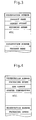
- Fig. 1 shows an apparatus integrating system represented by a shipment line for food articles such as candies.
- Apparatus which are integrated as a group in this system include an automatic weighing machine 1 for weighing objects such as materials and incomplete products and discharging a specified weight thereof, a packaging machine 2 for packaging weighed objects discharged from this weighing machine 1, a supplier 3 such as a conveyer for supplying objects supplied from outside to the weighing machine 1, a metal detector 4 for detecting metal objects which may have been mixed into packaged objects, a single item weight checker 5 for checking the weight of a packaged object, a sorter 6 for distinguishing between acceptable objects and unacceptable objects on the basis of a signal received from the weight checker 5, a packing apparatus 7 for placing a plurality of acceptable objects in each case, a case weight checker 8 for checking the weight of a case, and an automated storage house 9 for storing finished products packed in cases by sorting them.
- the apparatus 1-9 of this group are inter-connected so as to operate in a mutually coordinated manner such that objects supplied
- the automatic weighing machine 1 is of a well-known combinational weighing type, comprising a dispersion table with a center portion supported by a vibrator through suitable means so that objects to be weighed are vibrated and dispersed radially, a plurality of supply troughs radially disposed around it and supported by individual vibrators, a plurality of pool hoppers disposed in a circle for temporarily holding objects to be weighed which have been dropped from the individual supply troughs, and the same number of weigh hoppers as there are pool hoppers and disposed therebelow.
- the weighing machine 1 is also adapted to carry out combinational calculations on the basis of weight values determined by the weigh hoppers, select an optimum combination such that the sum of selected weight values will be equal to or the closest to a specified target weight value, and discharge the weighed objects from those of the weigh hoppers in the selected combination.
- the packaging machine 2 is of the type comprising a folding mechanism for folding a film sheet pulled out of a film roll such that its both side edges will be superposed one on top of the other, a longitudinal heater for sealing together the superposed edges of the folded film sheet to thereby make it into a cylindrical form, a film-transporting mechanism for transporting the cylindrically formed film sheet longitudinally by a specified distance while holding it in a transverse direction, a cutting mechanism for cutting the cylindrically formed film sheet, and a transverse sealer for transversely sealing along the cut edges, such that weighed objects (or products) discharged from the weighing machine 1 are dropped into the cylindrically formed film sheet while it is being transported by means of the film-transporting mechanism.
- the weighing machine 1 is provided with a control means 10 for controlling its operations, a memory means 11 for storing conditions and modes of operations of the apparatus group 1-9, a display means 12 for displaying the conditions and modes of operations of the apparatus group 1-9, a touch sensor 13 (serving as an input means) for detecting a contact position on the display screen of the display means 12, and a keyboard 14 (also serving as an input means) through which conditions of operations of the apparatus group 1-9 can be set.
- the control means 10 is adapted not only to control the weighing machine 1 on the basis of operations on the touch sensor 13 and the keyboard 14 but also to read out or write in data from or into the memory means 11 and to cause data to be displayed on the display means 12.
- the packaging machine 2 is provided with a control means 15 for controlling its operations, a memory means 16 for storing the conditions and modes of operations of the apparatus group 1-9, a display means 17 for displaying the conditions and modes of operations of the apparatus group 1-9, a touch sensor 18 (serving as an input means) for detecting a contact position on the display screen of the display means 17, and a keyboard 19 (also serving as an input means) through which conditions of operations of the apparatus group 1-9 can be set.
- a control means 15 for controlling its operations
- a memory means 16 for storing the conditions and modes of operations of the apparatus group 1-9
- a display means 17 for displaying the conditions and modes of operations of the apparatus group 1-9
- a touch sensor 18 serving as an input means
- a keyboard 19 also serving as an input means
- the supplier 3, the metal detector 4, the single item weight checker 5, the sorter 6, the packing apparatus 7, the case weight checker 8 and the storage house 9 are each provided with its own control means, memory means, display means, touch sensor and keyboard.
- the control means 10 of the weighing machine 1, the control means 15 of the packaging machine 2 and the control means of the other apparatus 3-9 are connected together through communication control means 21, 22, ... which are each associated with the control means 10, 15, ... of the individual apparatus 1-9 to control the transmission and reception of data, as well as communication line 23 connecting these communication control means 21, 22, ... .
- the communication control means 21, 22, ... and the communication line 23 together form what is herein referred to as the communication means 24 for exchanging data among the control means 10, 15, ... .
- the weighing machine 1 and the packaging machine 2 will be used as representatives of the apparatus group 1-9 to explain the methods of their operation and control in detail.
- the memory means 11 of the weighing machine 1 serves to store product names, target weights, speeds of weighing operations and various other weighing data as conditions of operation for different reservation numbers each representing a key item.
- the memory means 16 of the packaging machine 2 serves to store speeds of packaging operations, bag lengths, heater temperatures and various other packaging data as conditions of operation for different reservation numbers each representing a key item.
- Operation mode data representing the current mode of operation are displayed on the display screen of the display means 12 of the weighing machine 1 as shown, for example, in Fig, 5.
- various command keys such as START key 27 and STOP key 28, are visually displayed (as images).
- the visually displayed START key 27 is touched, it is detected by the touch sensor 13 and inputted to the control means 10 of the weighing machine 1 and a start signal corresponding to the touching operation on the START key 27 is outputted to the weighing machine 1. If the STOP key 28 is touched, a stop signal corresponding to this touching operation is outputted to the weighing machine 1.
- a PACKAGING MACHINE key 29 for operating the packaging machine 2 is visually displayed at a specified position on the display screen of the display means 12 of the weighing machine 1. If this PACKAGING MACHINE key 29 is touch-operated, signals are exchanged between the control means 10 and 15 of the weighing and packaging machines 1 and 2. Of the packaging data corresponding to reservation numbers stored in the memory means 16 for the packaging machine 2, predetermined data items of operation are called and caused to be displayed on the display screen of the display means 12. In this situation, the display screen displays modes of operation such as packaging speed, bag length, heater temperature and timing of packaging operations, that is, the current conditions of operation.
- the user can easily control the modes of operation of the packaging machine 2, even if it is situated farther away from the weighing machine 1, by touching command keys visually displayed on the display screen or physically operating numerical keys, for example, on the keyboard 14 to thereby change conditions of operation of the packaging machine 2 while observing the current modes of operation of the weighing machine 1.
- the user finds it necessary to reduce the weighing speed, while watching the modes of operation of the weighing machine 1, it is possible not only to so reduce the speed of weighing operations but also to reduce the packaging speed accordingly at the same time.
- the user will touch an EXIT key 30 also displayed on the display means 12 as shown in Fig. 5, thereby causing the original display to return on the display screen.
- a WEIGHING MACHINE key (not shown) for adjusting the weighing machine 1 is visually displayed at a specified position on the display screen of the display means 17 of the packaging machine 2. If this WEIGHING MACHINE key is touched, signals are exchanged between the control means 15 of the packaging machine and the control means 10 of the weighing machine 1 such that certain predetermined operation items are called from among the weighing data corresponding to the reservation number stored in the memory means 11 of the weighing machine. These items are caused to be displayed on the display screen of the display means 17, and modes of operation such as weighing speed and target weight are displayed as operation items.
- a user although situated near the packaging machine 2 but farther removed from the weighing machine 1, can operate on command keys visually displayed on the display screen or real numerical keys on the keyboard 19 to thereby control modes of operation of the weighing machine 1, while observing the conditions of operation of the packaging machine 2.
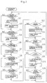
- the control means 10 for the weighing machine first examines whether or not there has been a change in the reservation number by an input from the keyboard 14 (Step S1). If the answer is YES, data on weighing operations corresponding to the new reservation number are retrieved from the memory means 11 (Step S2), and the new reservation number is transmitted to the control means of the other apparatus 2-9, inclusive of the control means 15 for the packaging machine 2 (Step S3).
- the control means 10 for the weighing machine 1 also examines whether or not a reservation number has been newly transmitted from any of the control means of the other apparatus 2-9 (Step 4). If one is found to have been newly transmitted, weighing data corresponding to the newly transmitted reservation number are retrieved (Step 5).
- control means 10 for the weighing machine 1 determines whether or not any weighing conditions have been set according to an input signal from the touch sensor 13 or the keyboard 14 (Step 6) and, if the answer is YES, these weighing conditions are recorded on a specified area of the memory means 11 (Step 7).
- control means 10 for the weighing machine 1 further determines that weighing conditions have been newly received through any of the other apparatus (Step 8), such received weighing conditions are similarly stored on another specified area of the memory means 11 (Step 9).
- control means 10 for the weighing machine 1 determines whether or not operating conditions of the other apparatus 2-9 have been changed according to an input from the touch sensor 13 or the keyboard 14 (Step 10). The answer is YES if, for example, a packaging condition has been changed and the changed packaging condition is transmitted to the control means 15 for the packaging machine 2 (Step S11).
- control means 10 for the weighing machine 1 determines whether a start-up command has been inputted through a signal from the touch sensor 13 (Step S12) and, if the answer is YES, the weighing machine 1 is activated and start-up signals are transmitted to the control means for the other apparatus 2-9 (Step S13).
- control means 10 for the weighing machine 1 determines whether or not a start-up signal has been received from a different apparatus (Step S15) and, if the answer is YES, this start-up signal is used as a trigger and the weighing machine 1 is activated (Step S16).
- control means 10 for the weighing machine 1 determines whether or not a stop command has been received through a signal from the touch sensor 13 (Step S17) and, if the answer is YES, the weighing machine 1 is stopped (Step S18) and a stop signal is transmitted to the control means of the other apparatus 2-9 (Step S19).
- the control means 10 for the weighing machine 1 also determines whether or not a stop signal has been received from any of the other apparatus (Step S20) and, if the answer is YES, this stop signal is used as a trigger and the weighing machine 1 is stopped (Step S21).
- the control means 15 for the packaging machine 2 first determines whether there has been a change in the reservation number on the basis of an input operation from the keyboard 19 (Step S1) and, if the answer is YES, data related to packaging corresponding to the new reservation number are retrieved from the memory means 16 (Step S2) and the new reservation number is transmitted to the control means for the other apparatus 1, 3-9 inclusive of the control means 10 for the weighing machine 1 (Step S3).
- the control means 15 for the packaging machine 2 also determines whether or not a reservation number has been newly transmitted from the control means of any of the other apparatus 1, 3-9 (Step S4) and, if the answer is YES, packaging data corresponding to the newly received reservation number are retrieved (Step S5).
- control means 15 for the packaging machine 2 determines whether or not packaging conditions have been newly set through input signals from the touch sensor 18 or the keyboard 19 (Step S6) and, if the answer is YES, these packaging conditions are recorded on a specified area of the memory means 16 (Step S7).
- control means 15 for the packaging machine 2 determines that packaging conditions have been newly received from another apparatus (Step S8), such packaging conditions are similarly recorded on another specified area of the memory means 16 (Step S9).
- control means 15 for the packaging machine 2 determines whether or not operating conditions of any of the other apparatus 1, 3-9 have been changed through input signals from the touch sensor 18 or the keyboard 19 (Step S10). If a weighing condition has been changed, for example, the answer is YES and the newly changed weighing condition is transmitted to the control means 10 for the weighing machine 1 (Step S11).
- control means 15 for the packaging machine 2 determines whether a start-up command has been inputted through a signal from the touch sensor 18 (Step S12) and, if the answer is YES, the packaging machine 2 is activated and start-up signals are transmitted to the control means for the other apparatus 1, 3-9 (Step S13).
- control means 15 for the packaging machine 2 determines whether or not a start-up signal has been newly received from a different apparatus (Step S15) and, if the answer is YES, this start-up signal is used as a trigger and the packaging machine 2 is activated (Step S16).
- control means 15 for the packaging machine 2 determines whether or not a stop command has been received through a signal from the touch sensor 18 (Step S17) and, if the answer is YES, the packaging machine 2 is stopped (Step S18) and a stop signal is transmitted to the control means of the other apparatus 1, 3-9 (Step S19).
- the control means 15 for the packaging machine 2 also determines whether or not a stop signal has been received from any of the other apparatus (Step S20) and, if the answer is YES, this stop signal is used as a trigger and the packaging machine 2 is stopped (Step S21).
- a user at the position of any of the apparatus 1-9 can not only set the operating conditions of the weighing machine 1 by operating on its input means 13 and 14 but also set the operating conditions of the other apparatus 2-9 through the communication means 24.
- the user it is possible for the user to be near any of the apparatus 1-9 and to observe its operating conditions while carrying out fine adjustments on another of the apparatus 1-9. This is how the operability of a shipping line can be improved according to the invention.
- each of the apparatus 1-9 is provided with its own memory means 11, 16, ...
- the second embodiment is different wherein a master file (or a master memory means) 33 is provided to some of the apparatus (such as the packaging machine 2) as shown in Fig. 8.
- the master file 33 serves to store work conditions for the apparatus 1-9 including system work conditions related to the entire group of apparatus such as quantity of production, yield data, product and code names of various products, weighed values, packaging speed and type of packaging material, and individual work conditions related to individual apparatus such as conditions on motions of hoppers of the weighing machine, timing of the mechanical motions of each apparatus, operating conditions of motors and heater temperature.
- the control means provided to each of the apparatus 1-9 is adapted to control the associated apparatus, the master file 33 and the display means.
- Communication means 24, including communication control means 21, 22, ... and a communication line 23, serves to transmit data among the control means 10, 15, ... of the individual apparatus 1-9 and also between the master file 33 and these control means 10, 15, ... .
- the user can operate the input means of one of the apparatus 1-9 to set not only operating conditions of the associated apparatus but also those of the other apparatus through the communication means 24.
- operability of the apparatus group improves because the user can be near any of the apparatus to watch its operation conditions while carrying out fine adjustments of another of the apparatus group.
- the master file 33 If the conditions of operating or the actual conditions of operation are stored in the master file 33, it becomes possible for the user to carry out performance management of the system.
- the overall management of the system as a whole becomes easier if the user can quickly grasp the rate at which defective products are being produced and identify which of the apparatus is defective.
- More than one of the apparatus 1-9 may be provided with a master file 33.
- a master file 33 may be provided with a master file 33.
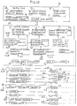
- Fig. 9 shows a third embodiment of the invention characterized as having a master file (master memory means) 33, a touch sensor (master input means) 34, a keyboard (master input means) 35, a display (master display means) 36, a master control means 37 and a communication control means 38 apart from the group of apparatus 1-9.
- This master file 33 serves to store work conditions for the apparatus 1-9 including system work conditions related to the entire group of apparatus such as quantity of products to be produced, yield data, product and code names of various products, weighed values, packaging speed and type of packaging material, and individual work conditions related to individual apparatus such as conditions on motions of hoppers of the weighing machine, timing of the mechanical motions of each apparatus, operating conditions of motors and heater temperature.
- the aforementioned system work conditions can be set from the touch sensor 34 or the keyboard 35.
- the display 36 is for displaying the system work conditions and the operating conditions of all apparatus 1-9 and comprises a high-level display device capable of displaying a large quantity of data related to the system.
- the display means 12, 17, ... associated with the individual apparatus 1-9 are intended to display only the individual work conditions and the operating conditions of the individual apparatus 1-9 and hence each comprise a lower-level display device with a relatively small capacity.
- the individual input means each associated with one of the individual apparatus 1-9 are used for setting the individual work conditions related to the corresponding apparatus as well as the apparatus associated with it. From the input means 13, 14 of the weighing machine 1, for example, individual work conditions related to the operation of the weighing machine as well as those related to the packaging machine 2, the supplier 3 and the single item weight checker 5, which are connected thereto, can be set.
- the control means associated with the individual apparatus are adapted to control the associated apparatus and its display means according to inputs received through the master input and individual input means.
- the control means 10 associated with the weighing machine 1 not only controls the weighing machine 1 but also displays data on the display means 12, reads and writes data from and into the master file 33 according to inputs received through the master input means 34 and 35 as well as inputs received through the input means 13 and 14 associated with the weighing machine.
- Communication means 24, including communication control means 21, 22, ... and the communication line 23, serves to transmit data among the individual control means 10, 15, ... of the individual apparatus 1-9 and also between the master control means 37 and these individual control means 10, 15, ... .
- data can be transmitted from the master control means 37 to the individual control means 10, 15, ... through the communication means 24 by operating the master input means 34 or 35.
- data can be transmitted from the individual control means 10, 15, ... to the master control means 37 through the communication means 24 by operating any of the input means 13, 14, 18, 19, ... of the individual apparatus 1-9.
- system work conditions such as the quantity of products to be produced and the product name set by an operation on the master input means 34 or 35 are transmitted through the communication means 24 to the control means of the individual apparatus 1-9, and the individual apparatus 1-9 are controlled according to such system work conditions that have been set.
- individual work conditions such as conditions on motions of hoppers of the weighing machine, timing of the mechanical motions of each apparatus, operating conditions of motors and heater temperature are displayed on the individual display means 12, 17, ... by an operation on any of the individual input means 13, 14, 18, 19, ... of the individual apparatus 1-9. If an individual work condition is changed by an operation on any of these individual input means 13, 14, 18, 19, .. , the change is also effected in the master file 33.
- the operations for setting the aforementioned individual work conditions are the same as described above for a system according to the first embodiment of the invention except the retrieval and storage of data are effected from and into the master file 33 (rather than the individual memory means 11, 16, ... as shown in Fig. 2 for a system according to the first embodiment).
- the operations for the weighing machine 1 and the packaging machine 2 are also as shown by the flow charts of Figs. 6 and 7.
- the individual apparatus 1-9 are provided with the input means 13, 14, 18, 19, ... for setting individual work conditions for the operations not only of themselves but also of those associated therewith, the user at any one of the apparatus 1-9 is able to operate on its control means to set not only the operating conditions of the apparatus associated with it but also those of the other apparatus through the communication means 24.
- the operability of the apparatus 1-9 can be improved since the user near one of the apparatus 1-9 can keep watching its operating conditions while carrying out fine adjustments of the others.
- the system according to the third embodiment of the invention does not require the user to indicate the new kind of product on each memory means of the individual apparatus 1-9.
- the user has only to pick out the new kind of products from the master file 33 through the master input means 34 or 35. In other words, a single operation can accomplish the purpose and hence the operability of the system is even more improved.
- the master input means 34 and 35, the master file 33, the master display means 36 and the master control means 37 are provided according to this embodiment such that data can be retrieved from the master file 33 by an operation at any of the input means 13, 14, 18, 19, ... of the individual apparatus 1-9 through their control means 10, 15, ... or the master control means 37, the total number of memory devices for the system can be smaller than if memory devices are provided individually to the apparatus 1-9. According to the third embodiment, furthermore, the stored data can be changed more easily because the user has only to update the master file 33.
- the master input means 34 and 35, the master file 33, the master display means 36 and the master control means 37 can be positioned separately and away from the group of apparatus 1-9, they may be set, for example, where the management post is located. This makes the control of the total system still easier.
- a high-capacity display device capable of displaying a large amount of data may be used only for the master display means 36, while relatively inexpensive smaller-capacity display devices may be used as the individual display devices associated with the individual apparatus required to display only limited amounts of data related to the operations of the associated apparatus.
- the total expense for the display system inclusive of the master display means 36 and the individual display means 12, 17, ... can be reduced. It goes without saying, however, that the invention does not teach away from the use of high-capacity display means for the individual apparatus 1-9.
- a supply weight detector 41 disposed on the upstream side (with respect to the flow direction of the articles to be weighed, packaged, etc.) of an apparatus unit composed of specified ones of the apparatus group 1-9 such as the supplier 3, the weighing machine 1, the packaging machine 2, the metal detector 4 and the single item weight checker 5.
- Detection signals w1 outputted from this supply weight detector 41 are adapted to be inputted to the control means 40 of the supplier 3.
- the master control means 37 includes a cumulative supply quantity calculating means 42 for receiving these detection signals w1 through the aforementioned control means 40 and cumulatively summing them for a fixed period of time to thereby calculate the total weight of the articles supplied during the same period of time.
- the aforementioned supply weight detector 41 and cumulative supply quantity calculating means 42 constitute what will be hereinafter referred to as a supply quantity detector means 43.
- Detection signals w2 indicative of weights and numbers of acceptable articles are outputted from the single item weight checker 5. These detection signals w2 are received through the control means 44 of the single item weight checker 5 by a first cumulative discharge quantity calculating means 45, which cumulatively sums these detection signals w2 for the same fixed period of time to thereby calculate the cumulative sum of the quantity of acceptable articles discharged from the single item weight checker 5 during this period of time.
- the first cumulative discharge quantity calculating means 45 is adapted to also calculate the net weights of the acceptable articles (with the weight of the bag subtracted) and the number of such acceptable articles.
- the aforementioned single item weight checker 5 and first cumulative discharge quantity calculating means 45 constitute what is hereinafter referred to as a first discharge quantity detecting means 46.
- the master control 37 also includes a first input-output difference calculating means 47 which is adapted to receive signals from the aforementioned cumulative supply quantity calculating means 42 and first cumulative discharge quantity calculating means 45 to calculate the difference between the cumulative supplied quantity and discharged quantity, thereby obtaining the yield of products from the apparatus unit composed of the apparatus 1-5.
- This yield represents the number of acceptable packaged products with respect to the total packaged products produced from the total weight of the articles that have been supplied. In other words, this represents the yield of the weighing machine 1.
- the master file 33 is provided with a first input-output quantity memory means 48 for storing the cumulative supply and discharge quantities thus calculated and their difference.
- Detection signals w3, indicative of the weight and number of acceptable articles outputted from the case weight checker 8 are adapted to be received through a control means 49 of the case weight checker 8 by a second cumulative discharge quantity calculating means 50 for cumulatively summing them over a fixed period of time to thereby calculate the cumulative weight and number of acceptable cases discharged from the case weight checker 8 during this time period.
- the second cumulative discharge quantity calculating means 50 is adapted to calculate not only the net weight of the products (with the weights of the packaging bags and cases subtracted) but also the number of the cases.
- the aforementioned case weight checker 8 and second cumulative discharge quantity calculating means 50 constitute what is hereinafter referred to as a second discharge quantity detecting means 51 for obtaining the cumulative discharged quantity during the aforementioned fixed period of time from the apparatus unit including all of the apparatus group 1-9.
- the master control means 37 further includes a second input-output difference calculating means 52 for receiving signals from the aforementioned cumulative supply quantity calculating means 42 and the second cumulative discharge quantity calculating means 50 to calculate the difference between the cumulative supplied quantity and the discharged quantity, thereby obtaining the yield of products from the apparatus unit composed of the apparatus 1-8. This yield represents the number of acceptable produced cases with respect to the total weight of the supplied articles.
- the master file 33 is provided with a second input-output quantity memory means 53 for storing the cumulative supply quantity thus calculated, the cumulative discharged quantity discharged from the case weight checker 8 and the difference therebetween.
- the yield of the apparatus unit 1-5 and hence that of the weighing machine 1 can be obtained. Since data on the yield are stored in the first input-output quantity memory means 48, the history of yield can be made available to the user.
- the second input-output difference calculating means 52 since the difference between the cumulative supply quantity supplied to the apparatus unit including all of the apparatus group 1-9 and the cumulative discharge amount therefrom can be calculated by the second input-output difference calculating means 52, the yield of the entire apparatus group 1-9 can be obtained. Since data on the yield are stored in the second input-output quantity memory means 53, the history of yield can also be made available to the user.
- detection signals w4 showing the number of packages from the packaging machine 2 and detection signals w5 indicative of the total number of products checked by the weight checker 5 inclusive of both acceptable and non-acceptable products are accumulated for a fixed period of time and their difference is calculated. Since unacceptably packaged products are visually spotted and removed from the shipping line before reaching the weight checker 5, the difference between the number of the packaged products (w4) and the total number of checked products (w5) represents the yield of the packaging machine 2.
- the system can be more effectively managed, for example, for the maintenance, inspection, necessity for replacement or repair of the apparatus, as well as the estimate for their effective lifetimes.
- the cumulative supply quantity calculating means 42 and the first and second cumulative discharge quantity calculating means 45 and 50 may be provided separately from the master control means 37 and unistructurally formed with the supply weight detector 41 and the weight checker 5 or 8, respectively.
- a yield can be calculated not only with respect to a number on the input side but also by comparing one weight with another weight or one number with another number.
- the master control means 37 includes a speed-yield correlation detecting means 56 for receiving the processing speed signals v through the control means 44 to thereby obtain a correlation between the processing speed and the yield at this processing speed calculated by the aforementioned first input-output difference calculating means 47 and the second input-output difference calculating means 52.
- the master memory means 33 is provided with a speed-yield correlation memory means 57 for storing the processing speed and the corresponding yield.
- the correlation between the processing speed v at which products are processed (or the line speed) and the yield is obtainable by the speed-yield correlation detecting means 56 and this correlation is stored as historical data by the speed-yield correlation memory means 57.
- This enables the user to set the processing speed optimally so as to improve the yield.
- the user In order to determine an optimal processing speed, however, the user must take into account not only the yield but also the defect ratios of the apparatus, as will be explained below.
- an apparatus unit consisting of apparatus 1-5 and an apparatus group consisting of apparatus 1-9 were considered.
- different apparatus units consisting of only one apparatus or a plurality of apparatus may be considered to obtain correlations between the processing speed v and the yield in a similar way.
- timing means may be provided to specified ones of the apparatus 1-9.
- the specified apparatus are the weighing machine 1 and the packaging machine 2.
- the control means 10 and 15 of the weighing machine 1 and the packaging machine 2 are individually provided with timing means 61 and 62 for measuring their operating times t1 and t2, respectively.
- the master control means 37 is provided with an operation timer 63 for measuring the operating time of the entire apparatus group 1-9, operating time ratio calculating means 64 for calculating the ratios of operating times of the corresponding machines 1 and 2 from a fixed period of time measured by the operation timer 63 and the aforementioned operating times t1 and t2, and a speed-operating time ratio correlation detecting means 65 for correlating the processing speed v with the calculated operating time ratio at the time.
- the master memory means 33 is similarly provided with a speed-operating time ratio correlation memory means 66 for correspondingly storing the aforementioned processing speed v, operating times t1 and t2 and the operating time ratio.
- the user can determine whether the weighing machine 1 has stopped because of a reason of its own or because there was a trouble in the packaging machine 2, causing the weighing machine 1 also to stop.
- the system can provide the user with important information for the system control.
- the real operating time ratio of the weighing machine 1 can be obtained by adding to its apparent operating time t1 the time during which it was stopped due to a trouble in the packaging machine 2.
- the timing means 61 and 62 may be adapted to measure the non-operating times of the corresponding machines 1 and 2 instead of their operating times.
- the correlation between the processing speed v and the operating time ratio can be similarly obtained for other apparatus besides the weighing machine 1 and the packaging machine 2.
- the master control means 37 is also provided with a failure ratio calculating means 70 for calculating what is hereinafter referred to as the failure ratio of a specified apparatus of the group 1-9 (the packaging machine 2 in the illustrated example).
- the weighing machine 1 which is disposed on the upstream side of the packaging machine 2, is adapted to output detection signals w6 representing the quantity of discharged products in terms of the number of bags which can be filled therewith (upstream processed quantity).
- the failure ratio calculating means 70 is adapted to receive not only these detection signals w6 but also detection signals w2 from the single unit weight checker 5 disposed on the downstream side of the packaging machine 2, representing the number of products found to be acceptable by the weight checker 5.
- the difference between these detection signals w6 and w2 is calculated by the failure ratio calculating means 70 as the failure rate for the packaging machine 2.
- the weighing machine 1 serves as upstream processed quantity detecting means for detecting the number of processed units of product on the upstream side
- the single unit weight checker 5 serves as downstream processed quantity detecting means for detecting the number of processed units of product on the downstream side.
- the master memory means 33 is provided with a failure rate memory means 71 for correspondingly storing the upstream processed quantity w6, the downstream processed quantity w2 and the difference therebetween.
- failure rate memory means 71 Since this rate is recorded in the failure rate memory means 71 as history of failure rate, the user can thereby diagnose the operating condition of the apparatus and carry out a suitable system management process including maintenance and inspection of the apparatus, judgment on the necessity of repairs thereon and estimates of their active lifetimes.
- Failure rates of machines other than the packaging machine 2 can be calculated similarly. Depending on the apparatus, the failure rate may be more conveniently calculated in terms of weights rather than numbers.
- the master control means 37 is further provided with a stop timing setting means 75 adapted to transmit to the control means 10, 15, 44, 49, ... of the individual apparatus 1-9 the numbers of products to be processed by them according to the number of final products to be shipped and to stop the operations of the apparatus 1-9 through their control means 10, 15, 44, 49, ... when these numbers have been reached.
- a stop timing setting means 75 adapted to transmit to the control means 10, 15, 44, 49, ... of the individual apparatus 1-9 the numbers of products to be processed by them according to the number of final products to be shipped and to stop the operations of the apparatus 1-9 through their control means 10, 15, 44, 49, ... when these numbers have been reached.
- a fourth embodiment of the invention illustrated in Fig. 11 is characterized in that the communication means 24 serves to connect a plurality of shipping lines 80 together, as well as between the apparatus group 1-9 of each shipping line 80.
- the master file (the master memory means) 33, the master input means 34 and 35, the master display means 36 and the master control means 37 are disposed separately from the plurality of shipping lines 80 such that these shipping lines 80 can be controlled and managed from one place.
- the fourth embodiment of the invention has the effect of bringing about the same advantages as the third embodiment of the invention described above.
- the apparatus group is not limited to the kinds of apparatus 1-9 shown in Fig. 1.
- the apparatus group may include other kinds of apparatus, for example, apparatus for manufacturing products and adding flavor to food items. If transporting apparatus are provided between apparatus of the group, such transportation apparatus may be included within the group of apparatus. It also goes without saying that the present invention can be applied to a system not including some of the apparatus included in the illustrated examples such as the storage house 9.
- the communication means 24 use may be made of a token ring, token passing or packet communication means.
- the present invention is applicable to various kinds of apparatus integrating system for automatically weighing, packaging and shipping products, inclusive of food products such as candies, vegetables and sea foods and industrial parts such as screws and springs.
Landscapes
- Engineering & Computer Science (AREA)
- Mechanical Engineering (AREA)
- General Engineering & Computer Science (AREA)
- Manufacturing & Machinery (AREA)
- Quality & Reliability (AREA)
- Physics & Mathematics (AREA)
- General Physics & Mathematics (AREA)
- Automation & Control Theory (AREA)
- Containers And Plastic Fillers For Packaging (AREA)
- Basic Packing Technique (AREA)
- Injection Moulding Of Plastics Or The Like (AREA)
- Arrangements For Transmission Of Measured Signals (AREA)
Abstract
Claims (8)
- Système d'intégration de machines comprenant un groupe de machines incluant une machine (1) de pesée destinée à peser des articles à fournir et une machine (2) d'emballage destinée à emballer les articles pesés, ledit groupe de machines fonctionnant d'une façon mutuellement coordonnée;chacune desdites machines comprenant:un moyen (11, 16) formant mémoire destiné à mémoriser les conditions de fonctionnement de ladite machine;des moyens (13, 14; 18, 19) d'entrée destinés à établir les conditions de fonctionnement de ladite machine;un moyen (12, 17) d'affichage destiné à afficher les conditions, et modes en cours, de fonctionnement de ladite machine; etun moyen (10, 15) de commande destiné à commander ladite machine, ledit moyen (11, 16) formant mémoire et ledit moyen (12, 17) d'affichage selon les entrées reçues par l'intermédiaire desdits moyens (13, 14; 18, 19) d'entrée;ledit système comprenant également un moyen (24) de communication destiné à transférer des données entre lesdits moyens de commande dudit groupe de machines, caractérisé en ce que chaque moyen (13, 14; 18, 19) d'entrée est utilisable pour établir les conditions de fonctionnement de l'autre machine (2, 1) par l'intermédiaire du moyen (24) de communication; et en ce que chaque moyen (12, 17) d'affichage peut également afficher les conditions, et modes en cours, de fonctionnement de l'autre machine (2, 1).
- Système d'intégration de machines comprenant un groupe de machines incluant une machine (1) de pesée destinée à peser des articles à fournir et une machine (2) d'emballage destinée à emballer les articles pesés, ledit groupe de machines fonctionnant d'une façon mutuellement coordonnée; certaine desdites machines ayant un moyen (33) formant mémoire maítre destiné à mémoriser les conditions de fonctionnement dudit groupe de machines;chacune desdites machines comprenant:des moyens (13, 14; 18, 19) d'entrée destinés à établir les conditions de fonctionnement de ladite machine (1, 2);un moyens (12, 17) d'affichage destiné à afficher les conditions, et modes en cours, de fonctionnement de ladite machine; etun moyens (10, 15) de commande destiné à commander ladite machine (1, 2), ledit moyen (33) formant mémoire maítre et ledit moyen (12, 17) d'affichage selon les entrées reçues par l'intermédiaire desdits moyens (13, 14; 18, 19) d'entrée;ledit système comprenant également un moyen (24) de communication destiné à transférer des données entre lesdits moyens (10, 15) de commande dudit groupe de machines et entre ledit moyen (33) formant mémoire maítre et lesdits moyens (10, 15) de commande dudit groupe de machines, caractérisé en ce que chaque moyen (13, 14; 18, 19) d'entrée est utilisable pour établir les conditions de fonctionnement de l'autre machine (2, 1) par l'intermédiaire du moyen (24) de communication; et en ce que chaque moyen (12, 17) d'affichage peut également afficher les conditions, et modes en cours, de fonctionnement de l'autre machine (2,1).
- Système d'intégration de machines comprenant un groupe de machines incluant une machine (1) de pesée destinée à peser des articles à fournir et une machine (2) d'emballage destinée à emballer les articles pesés, ledit groupe de machines fonctionnant d'une façon mutuellement coordonnée; ledit système comprenant:des moyens (34, 35) d'entrée maítres destinés à établir les conditions de fonctionnement du système liées aux opérations de tout ledit groupe de machines;un moyen (33) formant mémoire maítre destiné à mémoriser lesdites conditions de fonctionnement du système et lesdites conditions de fonctionnement individuel;un moyen (36) d'affichage maítre destiné à afficher lesdites conditions de fonctionnement du système et les modes de fonctionnement de tout ledit groupe de machines;un moyen (37) de commande maítre destiné à commander ledit moyen (33) formant mémoire maítre et ledit moyen (36) d'affichage maítre selon des entrées reçues par l'intermédiaire desdits moyens d'entrée maítres et des signaux provenant desdits moyens de commande individuels;des moyens (13, 14; 18, 19) d'entrée individuels prévus chacun dans une machine dudit groupe de machines pour établir les conditions de fonctionnement individuel de ladite machine et de celles desdites machines fonctionnant de façon mutuellement coordonnée avec elle;des moyens (12, 17) d'affichage individuels fournis chacun à une machine dudit groupe de machines pour afficher au moins lesdites conditions de fonctionnement individuel et le mode de fonctionnement dudit groupe de machines;des moyens (10, 15) de commande individuels prévus chacun dans une machine dudit groupe de machines pour commander ladite machine, ledit moyen d'affichage individuel et ledit moyen d'affichage maítre selon des entrées reçues par l'intermédiaire desdits moyens d'entrée maítres et desdits moyens d'entrée individuels; etledit système comprenant en outre un moyen (24) de communication destiné à transférer des données entre lesdits moyens (10, 15) de commande individuels et entre ledit moyen (37) de commande maítre et lesdits moyens (10, 15) de commande individuels, caractérisé en ce que chaque moyen (13, 14; 18, 19) d'entrée est utilisable pour établir les conditions de fonctionnement de l'autre machine (2, 1) par l'intermédiaire du moyen (24) de communication; et en ce que chaque moyen (12, 17) d'affichage individuel peut également afficher les conditions, et modes en cours, de fonctionnement de l'autre machine (2, 1).
- Le système d'intégration de machines de la revendication 3, comprenant en outre:un moyen (43) de détection de la quantité de fourniture destiné à détecter la quantité fournie cumulative desdits articles fournis dans une période de temps spécifiée à un ensemble de machines spécifié composé d'une ou plusieurs machines spécifiées dudit groupe de machines; etun moyen (46) de détection de la qualité de déchargement destiné à obtenir une quantité cumulative desdits articles déchargés dans ladite période de temps spécifiée à partir dudit ensemble de machines spécifié;Ledit moyen (37) de commande maítre incluant un moyen (52) de calcul de différence entrée-sortie destiné à détecter le rendement en calculant la différence entre ladite quantité de fourniture cumulative et ladite quantité de déchargement cumulative; et ledit moyen (33) formant mémoire maítre incluant un moyen (48) formant mémoire de quantité entrée-sortie destiné à mémoriser ladite quantité de fourniture cumulative, ladite quantité de déchargement cumulative et la différence entre elles.
- Le système d'intégration de machines de la revendication 4, comprenant en outre un détecteur (55) de vitesse de traitement destiné à détecter la vitesse de traitement à laquelle lesdits articles sont traités; ledit moyen (37) de commande maítre incluant en outre un moyen (56) de détection de la corrélation vitesse-rendement destiné à établir la corrélation de ladite vitesse de traitement avec ledit rendement au même moment, et ledit moyen (33) formant mémoire maítre incluant en outre un moyen (57) formant mémoire de corrélation vitesse-rendement destiné à mémoriser ladite vitesse de traitement et ledit rendement au même dit moment en correspondance entre eux.
- Le système d'intégration de machines de la revendication 3, comprenant en outre:un détecteur (55) de vitesse de traitement destiné à détecter la vitesse de traitement à laquelle lesdits articles sont traités; etun moyen (63) de chronométrage destiné à mesurer les temps de fonctionnement et de non fonctionnement d'une machine spécifiée dudit groupe de machines;ledit moyen (37) de commande maítre incluant:un moyen (64) de calcul de facteur d'utilisation destiné à calculer le facteur d'utilisation de ladite machine spécifiée durant une période de temps de fonctionnement spécifiée dudit groupe de machines à partir de ladite période de temps de fonctionnement spécifiée et desdits temps mesurés de fonctionnement et de non fonctionnement; etun moyen (65) de détection de la corrélation vitesse-facteur d'utilisation destiné à établir la corrélation entre ladite vitesse de traitement et ledit facteur d'utilisation au même moment; etledit moyen (33) formant mémoire maítre incluant en outre un moyen (66) formant mémoire de corrélation vitesse-facteur d'utilisation destiné à mémoriser ladite vitesse de traitement, ladite période de temps de fonctionnement spécifiée, lesdits temps de fonctionnement et de non fonctionnement et ledit facteur d'utilisation correspondant les uns avec les autres.
- Le système d'intégration de machines de la revendication 3, dans lequel lesdits articles sont transportés de l'amont vers l'aval séquentiellement par l'intermédiaire dudit groupe de machines, et une machine dudit groupe de machines comprend associés avec elle:un moyen (1) de détection de la quantité traitée en amont destiné à détecter la quantité traitée en amont définie comme la quantité desdits articles traités par celles desdites machines du côté amont de ladite machine; et un moyen (5) de détection de la quantité traitée en aval destiné à détecter la quantité traitée en aval définie comme la quantité desdits articles traités par celles desdites machines du côté aval de ladite machine;ledit moyen (37) de commande maítre incluant un moyen (70) de calcul du taux de défaillances destiné à calculer la différence entre ladite quantité traitée en amont et ladite quantité traitée en aval comme taux de défaillance de ladite machine; etledit moyen (33) formant mémoire maítre incluant en outre un moyen (71) formant mémoire de taux de défaillance destiné à mémoriser ladite quantité traitée en amont, ladite quantité traitée en aval et la différence entre elles.
- Le système d'intégration de machines de la revendication 3, dans lequel ledit moyen (37) de commande maítre inclut un moyen (75) de réglage du moment d'arrêt destiné à transmettre à chacun desdits moyens (7) de commande individuels un nombre cible de produits à traiter individuellement par celle correspondante desdites machines et à amener ledit moyen de commande individuel à arrêter le fonctionnement de ladite machine quand ledit nombre cible est atteint.
Applications Claiming Priority (2)
| Application Number | Priority Date | Filing Date | Title |
|---|---|---|---|
| PCT/JP1992/001315 WO1994008850A1 (fr) | 1992-10-08 | 1992-10-08 | Systeme d'integration de machines |
| US08/253,528 US5479756A (en) | 1992-10-08 | 1994-06-03 | Apparatus integrating system |
Publications (3)
| Publication Number | Publication Date |
|---|---|
| EP0614814A1 EP0614814A1 (fr) | 1994-09-14 |
| EP0614814A4 EP0614814A4 (fr) | 1997-06-04 |
| EP0614814B1 true EP0614814B1 (fr) | 2000-05-24 |
Family
ID=26433486
Family Applications (1)
| Application Number | Title | Priority Date | Filing Date |
|---|---|---|---|
| EP92921286A Expired - Lifetime EP0614814B1 (fr) | 1992-10-08 | 1992-10-08 | Systeme d'integration de machines |
Country Status (6)
| Country | Link |
|---|---|
| US (1) | US5479756A (fr) |
| EP (1) | EP0614814B1 (fr) |
| JP (1) | JP3373515B2 (fr) |
| DE (1) | DE69231097T2 (fr) |
| ES (1) | ES2145747T3 (fr) |
| WO (1) | WO1994008850A1 (fr) |
Cited By (1)
| Publication number | Priority date | Publication date | Assignee | Title |
|---|---|---|---|---|
| US7818081B2 (en) | 2008-05-19 | 2010-10-19 | The Procter & Gamble Company | Method for optimizing a manufacturing process having a plurality of interconnected discreet operating stations |
Families Citing this family (34)
| Publication number | Priority date | Publication date | Assignee | Title |
|---|---|---|---|---|
| US5706627A (en) * | 1994-02-02 | 1998-01-13 | Tetra Laval Holdings & Finance, S.A. | Control system for a packaging machine |
| JPH08119239A (ja) * | 1994-10-31 | 1996-05-14 | Sony Corp | カートン処理システム及びカートン処理方法 |
| ATE498552T1 (de) * | 1997-06-11 | 2011-03-15 | Ranpak Corp | System und verfahren zum verpacken |
| AU4529599A (en) * | 1998-07-24 | 2000-02-14 | Pulsar S.R.L. | Apparatus and method for conveying items |
| AU1807700A (en) * | 1998-10-14 | 2000-05-01 | R.A. Jones & Co. Inc. | Packaging machine control |
| JP2000118504A (ja) * | 1998-10-15 | 2000-04-25 | Ishida Co Ltd | 製袋充填包装システム |
| DE19914297A1 (de) * | 1999-03-29 | 2000-10-05 | Focke & Co | Verfahren und Einrichtung zur Steuerung einer (Zigaretten-)Fertigungs- und Verpackungsanlage |
| JP2001050803A (ja) | 1999-08-06 | 2001-02-23 | Ishida Co Ltd | 組合せ計量装置 |
| IT1320899B1 (it) | 2000-02-25 | 2003-12-10 | Pulsar Srl | Impianto per il trattamento di articoli e apparato di convogliamentodegli articoli utilizzabile in detto impianto. |
| US6629404B2 (en) | 2001-02-01 | 2003-10-07 | Hallmark Cards Incorporated | Method of and system for packaging articles |
| DE10313393A1 (de) | 2003-03-25 | 2004-10-07 | Focke & Co.(Gmbh & Co. Kg) | Produktions- und/oder Verpackungsanlage sowie Verfahren zu deren Betrieb |
| US20040260587A1 (en) * | 2003-06-20 | 2004-12-23 | Vanduyne Harry John | Distribution network and convertible packaging system |
| DE102005018251A1 (de) | 2005-04-19 | 2006-10-26 | Multivac Sepp Haggenmüller Gmbh & Co. Kg | Verpackungsmaschine |
| ITBO20050585A1 (it) * | 2005-09-28 | 2005-12-28 | Gd Spa | Macchina automatica per il trattamento di articoli dell'industria del tabacco e relativo metodo di controllo |
| TWI275529B (en) * | 2006-01-20 | 2007-03-11 | Hon Hai Prec Ind Co Ltd | System and method for auto-packaging parts |
| EP2075658A1 (fr) * | 2007-12-31 | 2009-07-01 | Tetra Laval Holdings & Finance SA | Architecture de système d'emballage intégré |
| EP2075661A1 (fr) * | 2007-12-31 | 2009-07-01 | Tetra Laval Holdings & Finance SA | Architecture de système d'emballage intégré |
| EP2075660A1 (fr) * | 2007-12-31 | 2009-07-01 | Tetra Laval Holdings & Finance SA | Architecture de système d'emballage intégré |
| EP2075659A1 (fr) * | 2007-12-31 | 2009-07-01 | Tetra Laval Holdings & Finance SA | Architecture de système d'emballage intégré |
| JP5419480B2 (ja) * | 2009-01-29 | 2014-02-19 | 大和製衡株式会社 | 計量包装システム |
| DE102009027269A1 (de) | 2009-06-29 | 2010-12-30 | Trumpf Werkzeugmaschinen Gmbh + Co. Kg | System und Verfahren zur Überwachung des Zustands einer Maschine |
| DE102011015849A1 (de) * | 2011-03-28 | 2012-10-04 | Nordischer Maschinenbau Rud. Baader Gmbh + Co. Kg | Vorrichtung und Verfahren zur automatischen Überwachung einer Vorrichtung zur Verarbeitung von Fleischprodukten |
| DE102012004341A1 (de) | 2012-03-07 | 2013-09-12 | Gea Cfs Germany Gmbh | Verpackungslinie |
| DE102013101628A1 (de) * | 2013-02-19 | 2014-08-21 | Hauni Maschinenbau Ag | Verfahren, Anordnung und Computerprogrammprodukt zum Betreiben und Steuern einer Produktionslinie zum Herstellen und/oder Verpacken von Artikeln der Tabak verarbeitenden Industrie |
| CN103144792A (zh) * | 2013-03-25 | 2013-06-12 | 红云红河烟草(集团)有限责任公司 | 一种可视可设定卷烟包装强制自检装置 |
| WO2015045092A1 (fr) * | 2013-09-27 | 2015-04-02 | 日本たばこ産業株式会社 | Dispositif d'aide à la fabrication de boîte de conditionnement et procédé d'aide à la fabrication |
| ES2744748T3 (es) * | 2015-01-16 | 2020-02-26 | Heat Control Inc | Método de control de la velocidad a la que un proceso anterior alimenta un producto acondicionado a un proceso posterior |
| JP6577199B2 (ja) | 2015-02-09 | 2019-09-18 | 株式会社イシダ | 包装システム |
| US20180111711A1 (en) * | 2015-05-26 | 2018-04-26 | Ishida Co., Ltd. | Production line configuration apparatus |
| CN108137182B (zh) * | 2015-08-06 | 2020-06-02 | 莫迪维克西普哈根牧勒股份及两合公司 | 具有过程控制的早开始功能的包装机 |
| DE102017102989A1 (de) * | 2017-02-15 | 2018-08-16 | Sig Technology Ag | Erhalten von Verpackungsanlagenzustandsdaten |
| JP6399136B1 (ja) * | 2017-03-31 | 2018-10-03 | オムロン株式会社 | 制御装置、制御プログラム、および制御システム |
| JP2022108429A (ja) | 2021-01-13 | 2022-07-26 | 株式会社イシダ | 管理装置及び物品管理システム |
| CN113184428A (zh) * | 2021-04-23 | 2021-07-30 | 大同市巴什卡机械制造有限公司 | 一种物料架及物料存储系统 |
Family Cites Families (9)
| Publication number | Priority date | Publication date | Assignee | Title |
|---|---|---|---|---|
| DE3028946A1 (de) * | 1979-08-02 | 1981-02-19 | Molins Ltd | Steuer- und kontrolleinrichtung fuer zigarettenverpackungsmaschinen |
| CH637228A5 (fr) * | 1980-03-27 | 1983-07-15 | Willemin Machines Sa | Dispositif de commande d'une machine ou d'une installation. |
| IT1169168B (it) * | 1983-02-15 | 1987-05-27 | Gd Spa | Sistema di controllo funzionale per trasduttori di ingresso di una unita' centrale di controllo e comando per macchine e/o dispositivi utilizzabili in linee di produzione e/o confezionamento di prodotti |
| JPH0672797B2 (ja) * | 1984-04-25 | 1994-09-14 | 株式会社石田衡器製作所 | 組合せ計量装置と包装機との連動システム |
| JPH062486B2 (ja) * | 1985-05-31 | 1994-01-12 | 株式会社寺岡精工 | 包装値付装置 |
| JPH06105181B2 (ja) * | 1985-10-16 | 1994-12-21 | 株式会社川島製作所 | 組合せ秤量包装装置 |
| US4827698A (en) * | 1988-03-03 | 1989-05-09 | Nabisco Brands, Inc. | Packaging weight control system |
| JPH03125929A (ja) * | 1989-10-11 | 1991-05-29 | Kubota Corp | 積込み原料払い出し装置 |
| US5027587A (en) * | 1990-09-05 | 1991-07-02 | Pitney Bowes Inc. | Methods and apparatus for controlling an inserter |
-
1992
- 1992-10-08 ES ES92921286T patent/ES2145747T3/es not_active Expired - Lifetime
- 1992-10-08 WO PCT/JP1992/001315 patent/WO1994008850A1/fr active IP Right Grant
- 1992-10-08 JP JP50562994A patent/JP3373515B2/ja not_active Expired - Fee Related
- 1992-10-08 EP EP92921286A patent/EP0614814B1/fr not_active Expired - Lifetime
- 1992-10-08 DE DE69231097T patent/DE69231097T2/de not_active Expired - Lifetime
-
1994
- 1994-06-03 US US08/253,528 patent/US5479756A/en not_active Expired - Lifetime
Cited By (1)
| Publication number | Priority date | Publication date | Assignee | Title |
|---|---|---|---|---|
| US7818081B2 (en) | 2008-05-19 | 2010-10-19 | The Procter & Gamble Company | Method for optimizing a manufacturing process having a plurality of interconnected discreet operating stations |
Also Published As
| Publication number | Publication date |
|---|---|
| WO1994008850A1 (fr) | 1994-04-28 |
| EP0614814A1 (fr) | 1994-09-14 |
| EP0614814A4 (fr) | 1997-06-04 |
| ES2145747T3 (es) | 2000-07-16 |
| DE69231097T2 (de) | 2000-11-02 |
| DE69231097D1 (de) | 2000-06-29 |
| JP3373515B2 (ja) | 2003-02-04 |
| US5479756A (en) | 1996-01-02 |
Similar Documents
| Publication | Publication Date | Title |
|---|---|---|
| EP0614814B1 (fr) | Systeme d'integration de machines | |
| JP3734883B2 (ja) | 生産ラインの管理方法並びに管理装置 | |
| KR101224851B1 (ko) | 포장 장치 및 포장 방법 | |
| JP4302821B2 (ja) | 計量及び製袋包装システム | |
| JPH0521169B2 (fr) | ||
| EP0978711A1 (fr) | Système de pesage et d'emballage | |
| JPH08313333A (ja) | ランク別組合せ計量方法、並びにそれに用いる計量装置及び計量システム | |
| JPH022091B2 (fr) | ||
| US4827698A (en) | Packaging weight control system | |
| AU2003264623A1 (en) | Weighing and flavoring system and packaging apparatus | |
| JP3413218B2 (ja) | 農産物の設定個数取出し装置 | |
| JP4509246B2 (ja) | 組合せ計量装置 | |
| JP2000193515A (ja) | 組合せ計量装置 | |
| JP2011191074A (ja) | 計量システムおよび包装システム | |
| JP4080083B2 (ja) | 計量システム | |
| JP2006029927A (ja) | 計量システム | |
| JP4027506B2 (ja) | 商品処理システム | |
| JP3917064B2 (ja) | 計量味付けシステム | |
| JP3533698B2 (ja) | 包装機の計数管理装置 | |
| JP6671775B2 (ja) | 計量包装検査システム | |
| JP4177482B2 (ja) | 物品処理システム | |
| JP3766849B2 (ja) | 選別組合せ秤における組合せ品の集計方法 | |
| JP2005106593A (ja) | 組合せ計量装置 | |
| JPH08219860A (ja) | 連包商品の製造システム | |
| JP2001004436A (ja) | 組合せ計量装置と、計量及び製袋包装システム |
Legal Events
| Date | Code | Title | Description |
|---|---|---|---|
| PUAI | Public reference made under article 153(3) epc to a published international application that has entered the european phase |
Free format text: ORIGINAL CODE: 0009012 |
|
| 17P | Request for examination filed |
Effective date: 19940705 |
|
| AK | Designated contracting states |
Kind code of ref document: A1 Designated state(s): DE ES FR GB IT |
|
| A4 | Supplementary search report drawn up and despatched |
Effective date: 19970414 |
|
| AK | Designated contracting states |
Kind code of ref document: A4 Designated state(s): DE ES FR GB IT |
|
| 17Q | First examination report despatched |
Effective date: 19971216 |
|
| RAP1 | Party data changed (applicant data changed or rights of an application transferred) |
Owner name: ISHIDA CO., LTD. |
|
| GRAG | Despatch of communication of intention to grant |
Free format text: ORIGINAL CODE: EPIDOS AGRA |
|
| GRAG | Despatch of communication of intention to grant |
Free format text: ORIGINAL CODE: EPIDOS AGRA |
|
| GRAH | Despatch of communication of intention to grant a patent |
Free format text: ORIGINAL CODE: EPIDOS IGRA |
|
| GRAH | Despatch of communication of intention to grant a patent |
Free format text: ORIGINAL CODE: EPIDOS IGRA |
|
| GRAA | (expected) grant |
Free format text: ORIGINAL CODE: 0009210 |
|
| AK | Designated contracting states |
Kind code of ref document: B1 Designated state(s): DE ES FR GB IT |
|
| REF | Corresponds to: |
Ref document number: 69231097 Country of ref document: DE Date of ref document: 20000629 |
|
| REG | Reference to a national code |
Ref country code: ES Ref legal event code: FG2A Ref document number: 2145747 Country of ref document: ES Kind code of ref document: T3 |
|
| ITF | It: translation for a ep patent filed |
Owner name: PORTA CHECCACCI & ASSOCIATI S.P.A. |
|
| ET | Fr: translation filed | ||
| PLBE | No opposition filed within time limit |
Free format text: ORIGINAL CODE: 0009261 |
|
| STAA | Information on the status of an ep patent application or granted ep patent |
Free format text: STATUS: NO OPPOSITION FILED WITHIN TIME LIMIT |
|
| 26N | No opposition filed | ||
| REG | Reference to a national code |
Ref country code: GB Ref legal event code: IF02 |
|
| PGFP | Annual fee paid to national office [announced via postgrant information from national office to epo] |
Ref country code: ES Payment date: 20081030 Year of fee payment: 17 |
|
| PGFP | Annual fee paid to national office [announced via postgrant information from national office to epo] |
Ref country code: IT Payment date: 20081028 Year of fee payment: 17 |
|
| PGFP | Annual fee paid to national office [announced via postgrant information from national office to epo] |
Ref country code: FR Payment date: 20081014 Year of fee payment: 17 |
|
| REG | Reference to a national code |
Ref country code: FR Ref legal event code: ST Effective date: 20100630 |
|
| PG25 | Lapsed in a contracting state [announced via postgrant information from national office to epo] |
Ref country code: FR Free format text: LAPSE BECAUSE OF NON-PAYMENT OF DUE FEES Effective date: 20091102 |
|
| PGFP | Annual fee paid to national office [announced via postgrant information from national office to epo] |
Ref country code: DE Payment date: 20101006 Year of fee payment: 19 |
|
| REG | Reference to a national code |
Ref country code: ES Ref legal event code: FD2A Effective date: 20110325 |
|
| PG25 | Lapsed in a contracting state [announced via postgrant information from national office to epo] |
Ref country code: IT Free format text: LAPSE BECAUSE OF NON-PAYMENT OF DUE FEES Effective date: 20091008 |
|
| PGFP | Annual fee paid to national office [announced via postgrant information from national office to epo] |
Ref country code: GB Payment date: 20101006 Year of fee payment: 19 |
|
| PG25 | Lapsed in a contracting state [announced via postgrant information from national office to epo] |
Ref country code: ES Free format text: LAPSE BECAUSE OF NON-PAYMENT OF DUE FEES Effective date: 20110314 |
|
| PG25 | Lapsed in a contracting state [announced via postgrant information from national office to epo] |
Ref country code: ES Free format text: LAPSE BECAUSE OF NON-PAYMENT OF DUE FEES Effective date: 20091009 |
|
| GBPC | Gb: european patent ceased through non-payment of renewal fee |
Effective date: 20111008 |
|
| PG25 | Lapsed in a contracting state [announced via postgrant information from national office to epo] |
Ref country code: DE Free format text: LAPSE BECAUSE OF NON-PAYMENT OF DUE FEES Effective date: 20120501 |
|
| REG | Reference to a national code |
Ref country code: DE Ref legal event code: R119 Ref document number: 69231097 Country of ref document: DE Effective date: 20120501 |
|
| PG25 | Lapsed in a contracting state [announced via postgrant information from national office to epo] |
Ref country code: GB Free format text: LAPSE BECAUSE OF NON-PAYMENT OF DUE FEES Effective date: 20111008 |