EP0608770A1 - Reissverschluss-Kuppelglieder und Verfahren zu dessen Herstellung - Google Patents
Reissverschluss-Kuppelglieder und Verfahren zu dessen Herstellung Download PDFInfo
- Publication number
- EP0608770A1 EP0608770A1 EP94100816A EP94100816A EP0608770A1 EP 0608770 A1 EP0608770 A1 EP 0608770A1 EP 94100816 A EP94100816 A EP 94100816A EP 94100816 A EP94100816 A EP 94100816A EP 0608770 A1 EP0608770 A1 EP 0608770A1
- Authority
- EP
- European Patent Office
- Prior art keywords
- head portion
- coupling
- coupling element
- guide groove
- Prior art date
- Legal status (The legal status is an assumption and is not a legal conclusion. Google has not performed a legal analysis and makes no representation as to the accuracy of the status listed.)
- Granted
Links
Images


Classifications
-
- A—HUMAN NECESSITIES
- A44—HABERDASHERY; JEWELLERY
- A44B—BUTTONS, PINS, BUCKLES, SLIDE FASTENERS, OR THE LIKE
- A44B19/00—Slide fasteners
-
- A—HUMAN NECESSITIES
- A44—HABERDASHERY; JEWELLERY
- A44B—BUTTONS, PINS, BUCKLES, SLIDE FASTENERS, OR THE LIKE
- A44B19/00—Slide fasteners
- A44B19/02—Slide fasteners with a series of separate interlocking members secured to each stringer tape
- A44B19/04—Stringers arranged edge-to-edge when fastened, e.g. abutting stringers
- A44B19/06—Stringers arranged edge-to-edge when fastened, e.g. abutting stringers with substantially rectangular members having interlocking projections and pieces
-
- Y—GENERAL TAGGING OF NEW TECHNOLOGICAL DEVELOPMENTS; GENERAL TAGGING OF CROSS-SECTIONAL TECHNOLOGIES SPANNING OVER SEVERAL SECTIONS OF THE IPC; TECHNICAL SUBJECTS COVERED BY FORMER USPC CROSS-REFERENCE ART COLLECTIONS [XRACs] AND DIGESTS
- Y10—TECHNICAL SUBJECTS COVERED BY FORMER USPC
- Y10T—TECHNICAL SUBJECTS COVERED BY FORMER US CLASSIFICATION
- Y10T24/00—Buckles, buttons, clasps, etc.
- Y10T24/25—Zipper or required component thereof
- Y10T24/2539—Interlocking surface constructed from plural elements in series
- Y10T24/255—Interlocking surface constructed from plural elements in series having interlocking portion with specific shape
- Y10T24/2552—Interlocking surface constructed from plural elements in series having interlocking portion with specific shape including symmetrical formations on opposite walls for engaging mating elements
-
- Y—GENERAL TAGGING OF NEW TECHNOLOGICAL DEVELOPMENTS; GENERAL TAGGING OF CROSS-SECTIONAL TECHNOLOGIES SPANNING OVER SEVERAL SECTIONS OF THE IPC; TECHNICAL SUBJECTS COVERED BY FORMER USPC CROSS-REFERENCE ART COLLECTIONS [XRACs] AND DIGESTS
- Y10—TECHNICAL SUBJECTS COVERED BY FORMER USPC
- Y10T—TECHNICAL SUBJECTS COVERED BY FORMER US CLASSIFICATION
- Y10T24/00—Buckles, buttons, clasps, etc.
- Y10T24/25—Zipper or required component thereof
- Y10T24/2539—Interlocking surface constructed from plural elements in series
- Y10T24/255—Interlocking surface constructed from plural elements in series having interlocking portion with specific shape
- Y10T24/2554—Interlocking surface constructed from plural elements in series having interlocking portion with specific shape including complementary formations on opposite walls for engaging mating elements
Definitions
- the present invention relates to a press-formed metal coupling element particularly suitable for use in a slide fastener which can be opened and closed in the forward direction and in the reverse direction by a pair of sliders mounted in either face-to-face or tail-to-tail confrontation on a pair of rows of discrete coupling elements, and a method of making such slide-fastener coupling element.
- the disclosed coupling element includes a beveled side wall formed by pressing or stamping the front end of a coupling head portion.
- the beveled side wall generally slopes down from a protrusion side toward a pocket side of the coupling element so that the front end of each coupling element does not interfere with a protrusion of the opposite coupling element when the slide fastener is closed in the reverse direction.
- the known coupling element may be made by a method or process disclosed in Japanese Patent Publication No. 63-6295 in which a metal wire that has been preformed into a Y profile is sliced into blank pieces which will become individual coupling elements, then a sliced blank piece is pushed into a head-forming station on a heading die where a protrusion and a corresponding pocket are formed by reciprocating a pocket punch toward the heading die.
- a ram having a cutoff die and a cutoff punch are relatively moved with each other. Using this relative movement, the upper edge of the Y-shaped metal wire is partly compressed by a shaping shoulder of the cutoff punch so as to form a round corner edge which will extend around a pocket of the finished coupling element.
- the opposed coupling elements are freely slidable in a perpendicular direction relative to the plane of engagement (viz. the plane of the slide fastener) immediately before they are engaged.
- a guide channel formed in the slider has a height somewhat larger than the thickness of the individual coupling elements, the coupling elements of the construction previously mentioned tend to wobble within the slider. As a result, the coupling elements are coupled or interengaged insufficiently, and the movement of the sliders becomes sluggish and requires some muscle effort.
- Another object of the present invention is to provide a simple method of making such slide-fastener coupling element.
- the present invention provides a slide-fastener coupling element which has a guide groove formed in the front end wall of a coupling head portion and opening away from opposed leg portions of the coupling element.
- the guide groove has a width reducing progressively in a direction from a pocket side toward a protrusion side of the coupling head portion.
- the depth of the guide groove reduces progressively toward the protrusion side of the coupling head portion.
- the coupling element of the construction above described is particularly useful when embodied in a coupling element chain of a slide fastener which can be opened and closed either of two reciprocal directions by a pair of sliders mounted in either face-to-face or tail-to-tail confrontation on the coupling element chain.
- one problem associated with the conventional bidirectionally openable slide fastener is that while the slide fastener is smoothly operative with the slider moving in one or the forward direction, the operation becomes sluggish or otherwise defective when the slider is moved in the other or the reverse direction because of the interference between the coupling-element's protrusion on one stringer and the front end of the coupling element on the opposite stringer.
- the foregoing problem does not take place because when the slide fastener is closed, the guide groove in each coupling element on one stringer receives and guides the coupling head portion of the mating coupling element on the opposite stringer.
- the coupling elements are, therefore, mutually engageable with least frictional resistance even when the slider is moved in the reverse direction.
- the present invention provides a method of making the slide-fastener coupling element of the construction above described, which method comprises the steps of: providing a metal wire having a Y-shaped profile including a head portion and opposed leg portions, the metal wire further having a longitudinal groove extending in a surface which forms a front end of the head portion facing away from the leg portions; slicing off a blank piece of an individual product thickness from the Y-shaped metal wire by reciprocating a cutoff punch having a generally U-shaped cutting portion which is substantially complementary in shape with, and slightly smaller in size than, the contour of the head portion of the Y-shaped metal wire; and thereafter, pressing with a pocket punch the head portion of the blank piece from a surface which is formed by said slicing-off step in the preceding cycle, so that the pressed head portion is shaped into a coupling head portion having, on its opposite sides, a protrusion and a corresponding pocket, and the groove in the blank piece is shaped into a guide groove having a width reducing progressively
- FIGS. 1 and 2 there is shown an individual slide-fastener coupling element 1 according to one embodiment of the present invention.
- the coupling element is made of metal and formed by a press.
- the press-formed, metal coupling element 1 is generally rectangular in shape and has a coupling head portion 2 and opposed leg portions 3 and 3 extending from an end (rear end) of the coupling head portion 2.
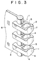
- the leg portions 3, 3 define therebetween a substantially oblong aperture (not designated) for receiving, as is well known, a longitudinal beaded edge of a stringer tape as shown in FIG. 3.
- the coupling head portion 2 has an engaging protrusion 4 on the top and a receiving pocket 5 (FIG. 2) on the bottom, the pocket 5 being complementary in shape with the contour of the protrusion 4 for receiving therein the protrusion 4 of the opposite coupling element when a slide fastener is closed.
- the coupling head portion 2 has a vertical guide groove 7 formed in a front end wall 6 thereof and opening away from the leg portions 3 for guiding the coupling head portion 2 of the opposite coupling element.
- the guide groove 7 extends between the top and the bottom of the coupling head portion 2 across the height of the front end wall 6.
- the guide groove 7 has a width reducing progressively in a direction from the pocket 5 side toward the protrusion 4 side.
- the depth of the guide groove 7 also reduces progressively in a direction from the pocket 5 side toward the protrusion 4 side.
- a series of discrete coupling elements 1 of the construction above described are attached to a longitudinal beaded edge of a stringer tape 8 to form a slide fastener stringer, as shown in FIG. 3.
- Two such stringers are paired together to form a slide fastener which, as shown in FIG. 4, can be opened and closed in either of two reciprocal directions by a pair of sliders 10, 10' slidably mounted in tail-to-tail confrontation on a coupling element chain 9 composed of two opposed rows of the coupling elements 1, 1.
- the sliders 10, 10' may be mounted in face-to-face confrontation on the coupling element chain 9.
- the rows of coupling elements 1, 1 are coupled or interengaged in the manner as shown in FIG. 5.
- each coupling element 1 on one stringer tape 8 slidably receives and guides the front end portion of the mating coupling element 1 on the opposite stringer tape 8 as the protrusion 4 and the mating pocket 5 of the coupling elements 1 are fit with each other.
- the coupling elements 1 are mutually engageable smoothly without causing slip or wobbling relative to the plane of engagement. This is also true when the coupling elements 1 are disengaged. Accordingly, the coupling elements 1 are mutually engageable and disengageable smoothly and stably with least frictional resistance even when the slide fastener (FIG. 4) is closed and opened by the slider 10' (FIG. 4).
- FIG. 6 shows a modified form of the coupling element according to the present invention.
- the modified coupling element 1 includes a round rib 11 projecting from the front wall of the pocket 5 and facing away from the front end wall 6 of the coupling head portion 2, the round rib 11 extending from an open end toward the bottom of the pocket 5.
- the coupling element 1 is able to pivot or turn about its projection 11 to some extent when a chain 9 (cf. FIG. 4) of the interengaged coupling elements 1 is subjected to a sudden vertical force or thrust tending to spread or rupture the coupling element chain 9.
- the coupling elements 1 above described are most conveniently made by a method or process described below.
- the process begins with a metal wire 12 that has been preformed into a Y profile including a substantially rectangular head portion 13 and two, somewhat diverging leg portions 15, 15 projecting from one end (rear end) of the square head 13.
- the Y-shaped metal wire 12 further has a longitudinal groove 14 extending in a surface which forms the opposite end (front end) of the head portion 13 facing away from the leg portions 15, 15.
- the width and depth of the groove 14 are constant throughout the length of the groove 14.
- the width of the groove 14 is slightly larger than the width of the guide groove 7 of the finished coupling element 1.
- a cutoff punch 16 is horizontally reciprocated relative to a cutoff die 18 to slice off a blank piece of an individual product thickness which will become individual coupling elements 1.
- the cutoff punch 16 has a substantially U-shaped cutting portion or blade 17 which is substantially complementary in shape with, and slightly smaller in size than the contour of the head portion 13 of the Y-shaped metal wire 12.
- the groove 14 in a sliced blank piece is slightly reduced in width.
- the sliced blank piece is pushed by the cutoff punch 16 into a head-forming die 20 having a head-forming recess or cavity 21, the cavity 21 being complementary in shape with the contour of the protrusion 4 of the finished coupling element 1.
- a pocket punch 22 and an associated presser pad 23 are advanced downwardly toward the head-forming die 20 to press or stamp the head portion 13 of the blank piece from the upper surface which is formed or produced by the slicing-off step in the preceding cycle.
- the material of the head portion 13 of the sliced blank piece is forced by the pocket punch 22 to flow into the head-forming cavity 21 so that a coupling head portion 2 having, on its opposite sides, a protrusion 4 and a corresponding pocket 5 is formed.
- the groove 14 in the sliced blank piece is shaped into a guide groove 7 whose width and depth reduce progressively toward the protrusion 4 side of the coupling head portion 2.
- the blank piece is shaped into a finished coupling element 1 of the construction shown in FIG. 1.
- the pocket punch 22 and the presser pad 23 are retracted upwardly, after which the head-forming die 20 supporting thereon one finished coupling element 1 is advanced in the right-hand direction on FIG. 8 toward a slide fastener stringer tape (not shown) which is supported in a vertical orientation.
- the leg portions 3 of the finished coupling element 1 are clamped on a longitudinal beaded edge of the stringer tape by a clincher (not shown) and then the stringer tape advances upwardly.
- the U-shaped cutting portion 17 of the cutoff punch 16 which is substantially complementary in shape with, but slightly smaller in size than, the contour of the head portion 13 of the Y-shaped metal wire 12. Accordingly, a blank piece, when it is sliced off from the Y-shaped metal wire 12 using the cutoff punch 16, the head portion 13 is slightly deformed or compressed such that the width of the entire head portion 13 and the width of the groove 17 are slightly reduced.
- the groove 17 of the thus compressed head portion 13 is substantially equal to the minimum width of the guide groove 7 in the finished coupling element 1.
- the groove 17 is spread at its upper side when the pocket punch 22 is reciprocated to press or stamp the head portion 13 of the sliced blank piece from the upper surface so as to form the pocket 5 and the corresponding protrusion 4. With this spreading, the groove 17 is shaped into a guide groove 7 which has a width reducing progressively from the pocket 5 side toward the protrusion 4 side of the coupling head portion 2.
- the cutting portion 17 of the cutoff punch 16 may most preferably be provided with a vertical projection 19 (FIG. 8) which is complementary in shape with the groove 14 formed in the sliced blank piece.
- the projection 19 has a width substantially equal to the minimum width of the guide groove 7 of the finished coupling element 1.
- the head-forming die 20 may most preferably be provided with a vertical projection 24 formed on the wall of the forming cavity 21 and having a shape complementary in contour to the shape of the guide groove 7 of the finished coupling element 1. That is, the projection 24 has a width and a depth that reduce progressively in a vertically downward direction.
- the groove 14 in the head portion 13 is shaped to have the width of the projection 19.
- the projection 24 forcibly shapes the groove 14 of the blank piece to have the shape and configuration of the guide groove 7 of the finished coupling element 1.
- the pocket punch 22 shown in FIG. 8 is replaced with a different pocket punch (not shown) which is recessed at its front end wall so as to form a groove complementary in shape with the contour of the round rib 11 (FIG. 6) of the finished coupling element 1.
- a different pocket punch (not shown) which is recessed at its front end wall so as to form a groove complementary in shape with the contour of the round rib 11 (FIG. 6) of the finished coupling element 1.
- a method provided in accordance with the present invention for making the slide-fastener coupling element of the construction above described comprises the steps of: providing a metal wire having a Y-shaped profile including a head portion and opposed leg portions, the metal wire further having a longitudinal groove extending in a surface which forms a front end of the head portion facing away from the leg portions; slicing off a blank piece of an individual product thickness from the Y-shaped metal wire by reciprocating a cutoff punch having a cutting portion which is substantially complementary in shape with, and slightly smaller in size than, the contour of the head portion of the Y-shaped metal wire; and thereafter, pressing with a pocket punch the head portion of the blank piece from a surface which is formed by said slicing-off step in the preceding cycle, so that the pressed head portion is shaped into a coupling head portion having, on its opposite sides, a protrusion and a corresponding pocket, and the groove in the blank piece is shaped into a guide groove having a width reducing progressively in a
- the coupling element 1 has a guide groove 7 which is formed in the front end wall 6 of the coupling element 1 and which has a width reducing progressively in a direction from the pocket side toward the protrusion side of the coupling head 2.
- the guide groove 7 in each coupling element 1 on one stringer slidably receives and guides the coupling head 2 of the mating coupling element 1 on the opposite stringer as the protrusion 4 and the mating pocket 5 are brought into mutual engagement with each other.
- opposed rows of coupling elements of the stringers can be smoothly and stably engaged together without causing vertical slip or wobbling relative to the plane of engagement.
- the slider is, therefore, movable smoothly.
- the coupling element 1 of the present invention is particularly useful when embodied in a slide fastener which can be opened in either of two reciprocal directions. Since the depth of the guide groove 7 reduces progressively toward the protrusion side, the coupling elements 1 of the slide fastener are mutually engageable and disengageable with least frictional resistance even when the slider is moved in the reverse direction.
- the coupling-element making method of the invention begins with a metal wire 12 of a Y-shaped profile.
- the Y-shaped metal wire 12 has a longitudinal groove 14 extending in a surface which forms a front end of the head portion 13 of the Y profile facing away from the leg portions 15 of the Y profile.
- the Y-shaped metal wire 12 is sliced off into blank pieces of individual product thickness by reciprocating a cutoff punch 16 having a cutting portion 17. Since the cutting portion 17 is substantially complementary in shape with, and slightly smaller in size than the contour of the head portion 13 of said Y-shaped metal wire 12, the width of the groove 14 is slightly reduced.
- a pocket punch 22 is driven to press or stamp the head portion 13 of the blank piece from a surface which is formed by said slicing off step in the preceding cycle, so that the pressed head portion 13 of the blank piece is shaped into a coupling head portion 2 having, on its opposite sides, a protrusion 4 and a corresponding pocket, and the groove 17 in said blank piece is shaped into a guide groove 7 having a width reducing progressively in a direction from a pocket side toward a protrusion side of said coupling head portion 2.
- the method described above does not require an apparatus or press which is complicated in construction. Accordingly, the coupling element can be manufactured easily and less costly.
Applications Claiming Priority (2)
| Application Number | Priority Date | Filing Date | Title |
|---|---|---|---|
| JP5013283A JP2803739B2 (ja) | 1993-01-29 | 1993-01-29 | スライドファスナー用務歯および務歯成形方法 |
| JP13283/93 | 1993-01-29 |
Publications (2)
| Publication Number | Publication Date |
|---|---|
| EP0608770A1 true EP0608770A1 (de) | 1994-08-03 |
| EP0608770B1 EP0608770B1 (de) | 1996-12-04 |
Family
ID=11828880
Family Applications (1)
| Application Number | Title | Priority Date | Filing Date |
|---|---|---|---|
| EP94100816A Expired - Lifetime EP0608770B1 (de) | 1993-01-29 | 1994-01-20 | Reissverschluss-Kuppelglieder und Verfahren zu dessen Herstellung |
Country Status (9)
| Country | Link |
|---|---|
| US (1) | US5394593A (de) |
| EP (1) | EP0608770B1 (de) |
| JP (1) | JP2803739B2 (de) |
| KR (1) | KR960009074B1 (de) |
| CN (1) | CN1060926C (de) |
| CA (1) | CA2113504C (de) |
| DE (1) | DE69401010T2 (de) |
| ES (1) | ES2095686T3 (de) |
| HK (1) | HK127797A (de) |
Cited By (2)
| Publication number | Priority date | Publication date | Assignee | Title |
|---|---|---|---|---|
| EP1029464A1 (de) * | 1999-02-10 | 2000-08-23 | Chung, Roger Chun-Yen | Unsichtbar Reisverschluss |
| EP1352583A1 (de) * | 2002-04-11 | 2003-10-15 | Ykk Corporation | Metalldraht zur Herstellung von Reissverschlusskuppelgliedern und ein aus diesem Metalldraht gefertigtes Kuppelglied |
Families Citing this family (28)
| Publication number | Priority date | Publication date | Assignee | Title |
|---|---|---|---|---|
| KR100441770B1 (ko) * | 1998-12-24 | 2004-11-03 | 주식회사 유니지퍼 | 지퍼제조장치및제조방법 |
| CN100387163C (zh) * | 2003-09-29 | 2008-05-14 | 胡志航 | 锌合金拉链齿粒 |
| CN1320970C (zh) * | 2004-09-15 | 2007-06-13 | 朱国光 | 一种拉链链牙的制作方法 |
| CN1320969C (zh) * | 2004-09-15 | 2007-06-13 | 朱国光 | 一种拉链链牙的制作方法 |
| CN1301160C (zh) * | 2004-09-15 | 2007-02-21 | 朱国光 | 一种拉链链牙的制作方法 |
| CN1320971C (zh) * | 2004-09-15 | 2007-06-13 | 朱国光 | 一种拉链链牙的制作方法 |
| CN101147946B (zh) * | 2006-09-19 | 2010-10-06 | 东莞大兴拉链厂有限公司 | 一种三点粟米牙金属拉链的制造工艺及其成型模具 |
| CN101152657B (zh) * | 2006-09-27 | 2010-10-06 | 东莞大兴拉链厂有限公司 | 一种滚珠牙金属拉链的制造工艺及其成型模具 |
| CN101152658B (zh) * | 2006-09-27 | 2010-10-06 | 东莞大兴拉链厂有限公司 | 一种雕花金属拉链的制造工艺及其成型模具 |
| WO2009128136A1 (ja) * | 2008-04-14 | 2009-10-22 | Ykk株式会社 | 金属製片面務歯及び両開き式スライドファスナー |
| JP5269106B2 (ja) * | 2009-02-04 | 2013-08-21 | Ykk株式会社 | ファスナーエレメント |
| CN101849730B (zh) * | 2010-04-28 | 2012-02-22 | 岳从平 | 一种金属拉链的加工方法 |
| CN102553999B (zh) * | 2010-12-31 | 2015-01-21 | 福建浔兴拉链科技股份有限公司 | 冲头机构及使用该冲头机构的拉链植齿机 |
| CN102793342B (zh) * | 2011-05-23 | 2016-02-17 | 上海浔兴拉链制造有限公司 | 一种凹点圆头s牙结构 |
| EP2749183B1 (de) * | 2011-08-24 | 2016-11-16 | YKK Corporation | Befestigungselement |
| CN102631055A (zh) * | 2012-04-29 | 2012-08-15 | 无锡金卫星实业有限公司 | 用于拉链的链牙 |
| CN102845938A (zh) * | 2012-04-29 | 2013-01-02 | 无锡金卫星实业有限公司 | 金属链牙 |
| CN103386448B (zh) * | 2012-05-10 | 2016-01-06 | Ykk株式会社 | 拉链用的啮合元件成形装置及拉链用的啮合元件 |
| EP2708151A1 (de) * | 2012-09-12 | 2014-03-19 | Riri Sa | Verfahren zur Herstellung von miteinander verbundenen Elementen eines Reißverschlusses |
| USD732424S1 (en) * | 2013-11-08 | 2015-06-23 | Wang Lap Ronny Ng | Slide fastener |
| USD741747S1 (en) * | 2013-12-17 | 2015-10-27 | Wang Lap Ronny Ng | Slide fastener |
| USD741748S1 (en) * | 2013-12-18 | 2015-10-27 | Wang Lap Ronny Ng | Slide fastener |
| USD741749S1 (en) * | 2014-02-22 | 2015-10-27 | Wang Lap Ronny Ng | Slide fastener |
| CN103829466B (zh) * | 2014-03-05 | 2016-01-13 | 福建浔兴拉链科技股份有限公司 | 双向链牙及拉链 |
| CN106560259B (zh) * | 2015-12-01 | 2018-12-14 | 福建晋江浔兴拉链科技有限公司 | 金属链牙、链牙成型模具及链牙加工方法 |
| WO2018211712A1 (ja) * | 2017-05-19 | 2018-11-22 | Ykk株式会社 | スライドファスナー |
| JP7083025B2 (ja) * | 2018-08-06 | 2022-06-09 | Ykk株式会社 | エレメント及びスライドファスナー |
| CN109527722B (zh) * | 2018-11-21 | 2021-08-24 | 浙江伟星实业发展股份有限公司 | 一种链牙及具有该链牙的拉链 |
Citations (4)
| Publication number | Priority date | Publication date | Assignee | Title |
|---|---|---|---|---|
| US2047925A (en) * | 1932-10-15 | 1936-07-14 | Hookless Fastener Co | Slide fastener |
| US2068354A (en) * | 1933-09-02 | 1937-01-19 | Hookless Fastener Co | Separable fastener |
| EP0064764A2 (de) * | 1981-05-13 | 1982-11-17 | Yoshida Kogyo K.K. | Verfahren und Vorrichtung zum Herstellen von Reissverschlussgliedern |
| EP0175198A2 (de) * | 1984-09-14 | 1986-03-26 | Yoshida Kogyo K.K. | Reissverschluss |
Family Cites Families (6)
| Publication number | Priority date | Publication date | Assignee | Title |
|---|---|---|---|---|
| USRE17881E (en) * | 1930-11-25 | Martin winterhalter | ||
| US1692196A (en) * | 1926-03-25 | 1928-11-20 | Mishawaka Rubber & Woolen Mfg | Slider-operated fastener |
| US2489718A (en) * | 1943-08-13 | 1949-11-29 | Louis H Morin | Method of producing double-action separable fasteners |
| US2628400A (en) * | 1949-10-06 | 1953-02-17 | Scovill Manufacturing Co | Slide fastener |
| JPS636295A (ja) * | 1986-06-25 | 1988-01-12 | 株式会社ブリヂストン | 高圧ホ−スの端部継手構造 |
| JPS6422505A (en) * | 1987-07-16 | 1989-01-25 | Fukui Tekkosho Kk | Core mold for block molding frame |
-
1993
- 1993-01-29 JP JP5013283A patent/JP2803739B2/ja not_active Expired - Fee Related
-
1994
- 1994-01-14 CA CA002113504A patent/CA2113504C/en not_active Expired - Fee Related
- 1994-01-18 US US08/181,913 patent/US5394593A/en not_active Expired - Lifetime
- 1994-01-20 ES ES94100816T patent/ES2095686T3/es not_active Expired - Lifetime
- 1994-01-20 DE DE69401010T patent/DE69401010T2/de not_active Expired - Lifetime
- 1994-01-20 EP EP94100816A patent/EP0608770B1/de not_active Expired - Lifetime
- 1994-01-28 KR KR94001591A patent/KR960009074B1/ko not_active IP Right Cessation
- 1994-01-28 CN CN94101113A patent/CN1060926C/zh not_active Expired - Fee Related
-
1997
- 1997-06-26 HK HK127797A patent/HK127797A/xx not_active IP Right Cessation
Patent Citations (4)
| Publication number | Priority date | Publication date | Assignee | Title |
|---|---|---|---|---|
| US2047925A (en) * | 1932-10-15 | 1936-07-14 | Hookless Fastener Co | Slide fastener |
| US2068354A (en) * | 1933-09-02 | 1937-01-19 | Hookless Fastener Co | Separable fastener |
| EP0064764A2 (de) * | 1981-05-13 | 1982-11-17 | Yoshida Kogyo K.K. | Verfahren und Vorrichtung zum Herstellen von Reissverschlussgliedern |
| EP0175198A2 (de) * | 1984-09-14 | 1986-03-26 | Yoshida Kogyo K.K. | Reissverschluss |
Cited By (4)
| Publication number | Priority date | Publication date | Assignee | Title |
|---|---|---|---|---|
| EP1029464A1 (de) * | 1999-02-10 | 2000-08-23 | Chung, Roger Chun-Yen | Unsichtbar Reisverschluss |
| EP1352583A1 (de) * | 2002-04-11 | 2003-10-15 | Ykk Corporation | Metalldraht zur Herstellung von Reissverschlusskuppelgliedern und ein aus diesem Metalldraht gefertigtes Kuppelglied |
| US6913835B2 (en) | 2002-04-11 | 2005-07-05 | Ykk Corporation | Metal wire rod for forming slide fastener coupling elements and slide fastener coupling element formed from the same metal wire rod |
| US7082649B2 (en) | 2002-04-11 | 2006-08-01 | Ykk Corporation | Metal wire rod for forming slide fastener coupling elements and slide fastener coupling element formed from the same metal wire rod |
Also Published As
| Publication number | Publication date |
|---|---|
| DE69401010T2 (de) | 1997-06-26 |
| KR940018045A (ko) | 1994-08-16 |
| HK127797A (en) | 1997-09-19 |
| KR960009074B1 (en) | 1996-07-10 |
| JPH06217810A (ja) | 1994-08-09 |
| DE69401010D1 (de) | 1997-01-16 |
| ES2095686T3 (es) | 1997-02-16 |
| CN1060926C (zh) | 2001-01-24 |
| CA2113504A1 (en) | 1994-07-30 |
| US5394593A (en) | 1995-03-07 |
| EP0608770B1 (de) | 1996-12-04 |
| CA2113504C (en) | 1996-09-24 |
| CN1095251A (zh) | 1994-11-23 |
| JP2803739B2 (ja) | 1998-09-24 |
Similar Documents
| Publication | Publication Date | Title |
|---|---|---|
| EP0608770B1 (de) | Reissverschluss-Kuppelglieder und Verfahren zu dessen Herstellung | |
| EP0698354B1 (de) | Kuppelglieder für Reissverschlüsse sowie Verfahren und Vorrichtung zur deren Herstellung | |
| US4163768A (en) | Method of manufacturing molded top stop | |
| US5495655A (en) | Method and apparatus for forming slide-fastener coupling element | |
| US4432126A (en) | Method of and apparatus for manufacturing slide fastener coupling elements | |
| CN1084608C (zh) | 拉链链合元件成形装置和剪切冲头 | |
| EP3045068B1 (de) | Reissverschlusskette, reissverschluss und befestigungselementherstellungsverfahren | |
| GB1600150A (en) | Method and apparatus for manufacture of coupling elements of slide fasteners | |
| EP0028358A2 (de) | Verfahren und Apparat zum Herstellen von Reissverschlussgliedern | |
| CA1176044A (en) | Apparatus for forming a space section in a pair of continuous slide fastener stringers | |
| US4110891A (en) | Method of attaching a separable bottom end stop to a pair of slide fastener stringers | |
| US4010520A (en) | Coupling element for slide fastener | |
| CA1283276C (en) | Sliding clasp fastener | |
| CA1238476A (en) | Method and apparatus for forming a space section in a pair of continuous concealed-slide-fastener stringers | |
| CA1156181A (en) | Method and apparatus for feeding conductive wire for anodizing process of slide fastener chain | |
| US4055882A (en) | Method of making a coupling element for a slide fastener | |
| US4462154A (en) | Holder for use in assembling top end-stops to slide fasteners | |
| EP0064764B1 (de) | Verfahren und Vorrichtung zum Herstellen von Reissverschlussgliedern | |
| US4349953A (en) | Method of manufacturing slide fastener coupling elements | |
| CA1124497A (en) | Method for manufacturing slide fastener elements | |
| US2106129A (en) | Method of making separable fasteners | |
| US2256796A (en) | Manufacture of separable fastener elements | |
| GB2098889A (en) | Method of and apparatus for manufacturing slide fastener coupling elements | |
| CA1156026A (en) | Method of manufacturing slide fastener coupling elements | |
| JPS636295B2 (de) |
Legal Events
| Date | Code | Title | Description |
|---|---|---|---|
| PUAI | Public reference made under article 153(3) epc to a published international application that has entered the european phase |
Free format text: ORIGINAL CODE: 0009012 |
|
| AK | Designated contracting states |
Kind code of ref document: A1 Designated state(s): DE ES FR GB IT |
|
| 17P | Request for examination filed |
Effective date: 19940818 |
|
| RAP1 | Party data changed (applicant data changed or rights of an application transferred) |
Owner name: YKK CORPORATION |
|
| GRAG | Despatch of communication of intention to grant |
Free format text: ORIGINAL CODE: EPIDOS AGRA |
|
| 17Q | First examination report despatched |
Effective date: 19960214 |
|
| GRAH | Despatch of communication of intention to grant a patent |
Free format text: ORIGINAL CODE: EPIDOS IGRA |
|
| GRAH | Despatch of communication of intention to grant a patent |
Free format text: ORIGINAL CODE: EPIDOS IGRA |
|
| GRAA | (expected) grant |
Free format text: ORIGINAL CODE: 0009210 |
|
| AK | Designated contracting states |
Kind code of ref document: B1 Designated state(s): DE ES FR GB IT |
|
| ITF | It: translation for a ep patent filed |
Owner name: JACOBACCI & PERANI S.P.A. |
|
| ET | Fr: translation filed | ||
| REF | Corresponds to: |
Ref document number: 69401010 Country of ref document: DE Date of ref document: 19970116 |
|
| REG | Reference to a national code |
Ref country code: ES Ref legal event code: FG2A Ref document number: 2095686 Country of ref document: ES Kind code of ref document: T3 |
|
| PLBE | No opposition filed within time limit |
Free format text: ORIGINAL CODE: 0009261 |
|
| STAA | Information on the status of an ep patent application or granted ep patent |
Free format text: STATUS: NO OPPOSITION FILED WITHIN TIME LIMIT |
|
| 26N | No opposition filed | ||
| REG | Reference to a national code |
Ref country code: GB Ref legal event code: IF02 |
|
| PGFP | Annual fee paid to national office [announced via postgrant information from national office to epo] |
Ref country code: ES Payment date: 20100126 Year of fee payment: 17 |
|
| PGFP | Annual fee paid to national office [announced via postgrant information from national office to epo] |
Ref country code: IT Payment date: 20100118 Year of fee payment: 17 Ref country code: FR Payment date: 20100208 Year of fee payment: 17 |
|
| PGFP | Annual fee paid to national office [announced via postgrant information from national office to epo] |
Ref country code: GB Payment date: 20100120 Year of fee payment: 17 Ref country code: DE Payment date: 20100114 Year of fee payment: 17 |
|
| GBPC | Gb: european patent ceased through non-payment of renewal fee |
Effective date: 20110120 |
|
| REG | Reference to a national code |
Ref country code: FR Ref legal event code: ST Effective date: 20110930 |
|
| PG25 | Lapsed in a contracting state [announced via postgrant information from national office to epo] |
Ref country code: FR Free format text: LAPSE BECAUSE OF NON-PAYMENT OF DUE FEES Effective date: 20110131 |
|
| PG25 | Lapsed in a contracting state [announced via postgrant information from national office to epo] |
Ref country code: GB Free format text: LAPSE BECAUSE OF NON-PAYMENT OF DUE FEES Effective date: 20110120 |
|
| REG | Reference to a national code |
Ref country code: DE Ref legal event code: R119 Ref document number: 69401010 Country of ref document: DE Effective date: 20110802 |
|
| PG25 | Lapsed in a contracting state [announced via postgrant information from national office to epo] |
Ref country code: IT Free format text: LAPSE BECAUSE OF NON-PAYMENT OF DUE FEES Effective date: 20110120 |
|
| REG | Reference to a national code |
Ref country code: ES Ref legal event code: FD2A Effective date: 20120220 |
|
| PG25 | Lapsed in a contracting state [announced via postgrant information from national office to epo] |
Ref country code: ES Free format text: LAPSE BECAUSE OF NON-PAYMENT OF DUE FEES Effective date: 20110121 |
|
| PG25 | Lapsed in a contracting state [announced via postgrant information from national office to epo] |
Ref country code: DE Free format text: LAPSE BECAUSE OF NON-PAYMENT OF DUE FEES Effective date: 20110802 |