EP0607480A1 - Procédé et dispositif pour la production de poutres en bois lamellées et autres produits par des planches assemblées par dents collées - Google Patents
Procédé et dispositif pour la production de poutres en bois lamellées et autres produits par des planches assemblées par dents collées Download PDFInfo
- Publication number
- EP0607480A1 EP0607480A1 EP93100716A EP93100716A EP0607480A1 EP 0607480 A1 EP0607480 A1 EP 0607480A1 EP 93100716 A EP93100716 A EP 93100716A EP 93100716 A EP93100716 A EP 93100716A EP 0607480 A1 EP0607480 A1 EP 0607480A1
- Authority
- EP
- European Patent Office
- Prior art keywords
- boards
- glue
- pressure
- glulam
- glued
- Prior art date
- Legal status (The legal status is an assumption and is not a legal conclusion. Google has not performed a legal analysis and makes no representation as to the accuracy of the status listed.)
- Granted
Links
Images


Classifications
-
- B—PERFORMING OPERATIONS; TRANSPORTING
- B27—WORKING OR PRESERVING WOOD OR SIMILAR MATERIAL; NAILING OR STAPLING MACHINES IN GENERAL
- B27M—WORKING OF WOOD NOT PROVIDED FOR IN SUBCLASSES B27B - B27L; MANUFACTURE OF SPECIFIC WOODEN ARTICLES
- B27M1/00—Working of wood not provided for in subclasses B27B - B27L, e.g. by stretching
- B27M1/08—Working of wood not provided for in subclasses B27B - B27L, e.g. by stretching by multi-step processes
-
- B—PERFORMING OPERATIONS; TRANSPORTING
- B27—WORKING OR PRESERVING WOOD OR SIMILAR MATERIAL; NAILING OR STAPLING MACHINES IN GENERAL
- B27M—WORKING OF WOOD NOT PROVIDED FOR IN SUBCLASSES B27B - B27L; MANUFACTURE OF SPECIFIC WOODEN ARTICLES
- B27M3/00—Manufacture or reconditioning of specific semi-finished or finished articles
- B27M3/0013—Manufacture or reconditioning of specific semi-finished or finished articles of composite or compound articles
- B27M3/002—Manufacture or reconditioning of specific semi-finished or finished articles of composite or compound articles characterised by oblong elements connected at their ends
-
- B—PERFORMING OPERATIONS; TRANSPORTING
- B27—WORKING OR PRESERVING WOOD OR SIMILAR MATERIAL; NAILING OR STAPLING MACHINES IN GENERAL
- B27M—WORKING OF WOOD NOT PROVIDED FOR IN SUBCLASSES B27B - B27L; MANUFACTURE OF SPECIFIC WOODEN ARTICLES
- B27M3/00—Manufacture or reconditioning of specific semi-finished or finished articles
- B27M3/0013—Manufacture or reconditioning of specific semi-finished or finished articles of composite or compound articles
- B27M3/006—Manufacture or reconditioning of specific semi-finished or finished articles of composite or compound articles characterised by oblong elements connected both laterally and at their ends
Definitions
- a solution is sought to produce normal glued laminated timber of different widths with a glulam press without emptying the press, economically producing excess widths from several narrow planks as well as large top and bottom chords, gluing them statically favorably at large distances with smaller cross sections.
- a combination with other materials should be used to apply or apply layers against fire, temperature, acoustics, moisture or other effects.
- this is achieved in that the continuous gluing is already carried out in multi-channel systems with the same or different widths.
- a package of different widths can be processed for the multi-lane press corresponding to the length of the end product.
- the different widths can be stacked in height and easily called up as required.
- the glue information for the production of the glulam beams is closed, spring-loaded in width and heatable.
- the individual components or the glue can be heated for faster chemical reaction (setting).
- the glue specification is suitable for holding several boards.
- the conventional method of roller transport is not suitable for achieving a continuous speed due to the glue specification, because a resilient sealing of the board guide due to the glue specification results in an uneven speed, as well as an associated unequal amount of glue application.
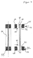
- the glue indication has a resilient stop according to FIG. 9 due to the compressed air cylinder 128, which acts on the board width and a slide for the metered opening of the slot-shaped openings 112 according to FIG. 8.
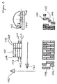
- the assembled glue width is turned by 180 degrees so that there is an overlap of the different board widths for the optimal gluing.
- the boards of the same or different widths specified with glue are placed in the glulam press, positioned and pressed.
- the press has a further pressure unit, which takes over the backflow protection and a sliding pressure unit for maintaining the glue pressure when the counter pressure is removed.
- the 2 pressure units acting on one level have a much higher pressure than the one required for gluing to the glulam beam. This favors the manufacture of the box girder and other profiles.
- the first rigid pressure unit is used for gluing the lower belt and the second movable one for the upper belt. In this way you can economically produce I-profiles and other suitable surface gluing.
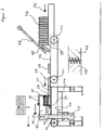
- the boards from channel 32 or 31 arriving from the finger press are removed from the transport system before the glue is specified.
- Figure 7 taken and pushed by the driver 93 or 94 in the direction of arrow 96 through the glue. Contrary to the usual way of transport by feed roller.
- the glue is specified in accordance with Figure 8.
- the glue emerges through continuously narrowing slots 104, in the form of a cord according to FIGS. 8, 117.
- the slide 109 releases the required amount by moving in the direction of the arrow 110 + 111.
- the drive 113 of the slide 109 closes the opening 104.
- the slide 109 opens.
- the glue generally consists of two or more components which are fed through the bores 122 + 123 of the tubes 120 + 121.
- the holes are advantageously made so that the two components 115 + 116 mix.
- the filling quantity of the glue 117 can be monitored by controls, not shown.
- the chemical setting of the two components can be accelerated by heating one or both components.
- the glue specification and pipes can be heated for this purpose.
- the width of the glue is infinitely adjustable and the elastic pressure of cylinder 128 adapts the glue to the board widths and prevents the glue from escaping to the side. Due to the heating of the glue, the setting is quick and a leaking glue must be quickly fed back to the glue specification in a known manner. For this reason it is a good one Sealing advantageous.
- the metering pumps 133 + 134 convey the glue with infinitely variable pressure and in dosable quantities through the pipes through the holes 122 + 123 into the glue container.
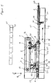
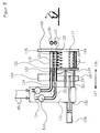
- the boards 8 provided with glue by the glue are transported on the heatable pressure piece 24 and pressed by the insertion cylinder 2 in the direction of the arrow 9 against the glulam beam to be glued.
- the cylinder is pushed back by the wood thickness because the back pressure in cylinder 3 is lower due to the smaller piston area while maintaining the number of bars.
- the heatable pressure piece 24 remains effective with the force of the cylinder 2 on the back of the inserted board 23.
- the heatable pressure piece 24 transfers the infinitely variable temperature to the back of the boards 23 until the next boards 23 to be glued are ready for insertion in the direction of the arrow 12.
- the rhythm from boards to boards is 30 -60 seconds. This time is sufficient to accelerate the chemical or physical setting of the glue in the glue joint.
- the printing unit 4 with the pressure piece 8 in the direction of the arrow 12 comes into operative position so that the pressure in the glued laminated timber is maintained.
- the cylinder 2 goes back, the boards 23 are pushed in the direction of arrow 12 onto the heatable pressure piece 24.
- the pressure piece 24 is pushed in the direction of arrow 9 in a force-locking manner with the previously heated boards 23, then the pressure on the pressure piece 8, the printing unit 4, is reduced.
- the energy acting in cylinder 2 in the direction of arrow 9 can push back the pressure piece 8 of the impression cylinder 3 by the wood thickness of the boards 23.
- the last boards 23 of a glulam beam width are not specified with glue.
- the piston stroke of the cylinder 3 is advantageously as long as the max. glulam width to be produced. If an empty joint indicates the end of the width, then, or a few inserts later, the pressure piece 8 goes into active position through the hydraulic cylinder 7 of the pressure unit 5. The pressure piece 8 is withdrawn by the cylinder 3 and the glued glulam beam is lifted in the direction of the arrow 11 and transported away in a known manner for surface treatment. The pressure is maintained between the pressure units 4 + 5 and the connection 22 between the pressure pieces 8 absorbs the forces acting in the direction of the arrow 9 + 10.
- the boards 23 can be inserted further, the adjustable counterforce is taken over by the pressure unit 5 by friction until cylinder 3 with the pressure piece is in the active position. Friction is only possible if the glue has set in the glulam beam, because the possible deformation of the individual boards would destroy the glue joint. Therefore, the pressure piece 8 of the cylinder 3 must initially take over the counter pressure. Since the glulam beams are manufactured in different widths, the mobile printing unit 5 is brought into the required position by the driver 13 in the direction of arrow 10 or 9 by the drive 15. On the construction 1, the perforated rail with the holes 21 is attached, where the compressed air cylinder 20, the bolts 19 in Lock front flange 18. In the production of wide beams according to FIG.
- the boards arriving from the finger press in channel 31 + 32 are pushed into the press at once by the glue indication.
- the second pair of boards is turned by 180 degrees in the respective arrow direction 127 by the turning device according to FIG. 2, or the boards are called up by the magazines 146 + 147 accordingly.
- the gluing takes place in the glulam press according to FIG. 1.
- the heatable pressure piece 24 serves as a positioning stop for the glulam 55.
- the beam width is determined by the distance 58 between the beams 51 + 57. For this reason, the mobile printing unit 5 can be moved and locked in the direction of the arrow 9 + 10.
- the boards 66 are first glued to glulam.
- the impression cylinder 3 remains in its active position with its pressure piece until the narrower woods 67 are to be glued.
- the cylinder 2 has an extended piston stroke in the direction of arrow 9 to the end of the press shoe 8.
- the first three narrower boards are glued under a lower pressure in the direction of arrow 12 of the first printing unit.
- the output of the hydraulic line 27 is blocked until the narrow boards match the edge 26, after which the pressure is maintained again by the pressure relief valve of the cylinder 3, which is not shown.
- the half profile 66 + 67 obtained in this way is mixed with the glue 62 glued again in the glulam press according to FIG. 1 with the mobile printing unit 5.
- the glue specification is advantageously carried out by means of a commercially available glue specification by hand.
- the cavity can also be used partially to insert empty lines.
- a fire-retardant layer can advantageously be applied by pressing. Due to the different widths, there are problems in the production of glulam beams. You have to change all the existing presses to different widths, which requires a lot of work. This was the object of the invention to solve it with a new glulam press.
- the pressure units can be brought into the active position that different widths can be processed.
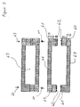
- FIG. 6 shows three different widths of a glulam beam which was manufactured in FIG. 1.
- the printing unit 5 also serves to ensure that when switching from one glulam width to the other, the second upper pressure is brought into the operative position by shifting, so that gluing from one board width to the other can take place without a significant changeover time.
- the insertion cylinder 2 can have a longer stroke, which extends over the length of the acting pressure shoe 8 of the upper pressure unit 4, which can be movable and adjustable to achieve the required positions.
- a drive can be provided to completely empty the glulam press according to FIG.
- the pressure shoe of the printing unit 4 can be connected to the pressure shoe 5 by the part 22, in order to compensate for the back pressure from the direction of the arrows 9 and 10.
- the insertion cylinder 2 is designed larger in the piston area than the back pressure cylinder 3 which determines the gluing pressure.
- the back pressure is set by a pressure limiting valve. With this design, no control and monitoring of the glue pressure is required. Only the BAR number of the pressure relief valve is used for the calculation of the glue pressure. All other cylinders of the insertion and top pressure are at least larger by the piston area, as required by the coefficient of friction.
- the impression cylinder 3 can be fixed in the bores at certain intervals.
- the piston stroke is advantageously slightly more than the possible gluing width of the glulam beam. If a board has not been specified with glue, there is an empty joint that separates the glulam beam to be glued from the next one. If the empty joint has passed the pressure piece, the second pressure unit is activated.
- the counter-pressure cylinder is loaded on the other side and the glulam beam is transported by a built-in roller system with a sufficient distance from the printing unit 5 in the longitudinal or transverse direction via the 4-sided planer into the finished store or for beam processing. Immediately after the plywood support is lifted, the impression cylinder returns to the active position.
- the printing unit 5 maintains the glue pressure and can use friction to pick up the next board for gluing in the plywood press.
- the pressure pieces 8 of the pressure units 4 + 5 can be heated.
- the glue 62 is only indicated on the upper side and the lower side can be heated up by the heated pressure pieces 8 in such a way that the glue is set in a few minutes after the upper side has been brought in and the pressure has applied.
- the heatable pressure pieces 8 can act on the glued laminated timber below.
- the glue 52 can be applied to the plate 50.
- the pressure of the printing units 4 + 5 acts and heats the surface, whereupon the glue-laminated wood specified with glue is glued as is known.
- the glulam press Figure 1 consists of a large number of presses arranged side by side. In the intervals lifting and transport devices can be introduced for handling, positioning and removal of the glued glulam.
- the glulam press can be created horizontally or vertically at any angle.
- a running film inserted in the joint separates the glulam.
- the insert can then consist of several hydraulic cylinders that work side by side.
- the insertion in the pressing position takes place when the boards indicated with glue are on hold in the longitudinal direction acc. Fig. 10.
- the glue information can be positioned directly in front of the press infeed. This type of gluing is particularly useful in the manufacture of narrow beams to utilize the installed forces.
- the rhythm is then twice as long, which means that depending on the length of the boards, the pressure piece can remain in the active position for up to 2 minutes, the setting times are then shorter.
- impression cylinder 3 To adjust the impression cylinder 3 in the bores 21 of the individual positions, snap-in bolts 19 are provided which are brought into effect by lifting cylinders 20. An adjustment by friction or other known type is possible.
- the impression cylinder 3 and the upper printing units 4 + 5 or more can be attached to transport chains, ropes or racks to achieve the required positions.
Priority Applications (2)
| Application Number | Priority Date | Filing Date | Title |
|---|---|---|---|
| EP19930100716 EP0607480B1 (fr) | 1993-01-18 | 1993-01-18 | Procédé et dispositif pour la production de poutres en bois lamellées et autres produits par des planches assemblées par dents collées |
| DE59307743T DE59307743D1 (de) | 1993-01-18 | 1993-01-18 | Verfahren und Vorrichtungen zur Herstellung von endlosen Hölzern durch Keilzinkung zu Brettschichtholzträgern und anderen Holzerzeugnissen |
Applications Claiming Priority (1)
| Application Number | Priority Date | Filing Date | Title |
|---|---|---|---|
| EP19930100716 EP0607480B1 (fr) | 1993-01-18 | 1993-01-18 | Procédé et dispositif pour la production de poutres en bois lamellées et autres produits par des planches assemblées par dents collées |
Publications (2)
| Publication Number | Publication Date |
|---|---|
| EP0607480A1 true EP0607480A1 (fr) | 1994-07-27 |
| EP0607480B1 EP0607480B1 (fr) | 1997-11-26 |
Family
ID=8212541
Family Applications (1)
| Application Number | Title | Priority Date | Filing Date |
|---|---|---|---|
| EP19930100716 Expired - Lifetime EP0607480B1 (fr) | 1993-01-18 | 1993-01-18 | Procédé et dispositif pour la production de poutres en bois lamellées et autres produits par des planches assemblées par dents collées |
Country Status (2)
| Country | Link |
|---|---|
| EP (1) | EP0607480B1 (fr) |
| DE (1) | DE59307743D1 (fr) |
Cited By (4)
| Publication number | Priority date | Publication date | Assignee | Title |
|---|---|---|---|---|
| EP1050636A3 (fr) * | 1999-05-03 | 2001-10-04 | Riko Hise, D.O.O. | Système modulaire d'éléments de construction en bois avec des cadres en bois et leur procédé de fabrication |
| DE102013109206A1 (de) * | 2013-08-26 | 2015-02-26 | Ladenburger Gmbh | Verfahren zur Herstellung eines aus mehreren Schnitthölzern bestehenden Konstruktionsschichtholzes sowie Konstruktionsschichtholz |
| EP3208060A1 (fr) * | 2016-02-16 | 2017-08-23 | Fill Gesellschaft m.b.H. | Procédé et dispositif de fabrication de bois lamellé-collé |
| CN108117006A (zh) * | 2018-02-02 | 2018-06-05 | 柳城县迪森人造板有限公司 | 一种用于木板涂胶后的搭放升降台 |
Citations (6)
| Publication number | Priority date | Publication date | Assignee | Title |
|---|---|---|---|---|
| US1901598A (en) * | 1930-05-28 | 1933-03-14 | John L Herzog Co | Machine for making panel core stock from mill clippings and the like |
| DE1991208U (de) * | 1964-10-23 | 1968-08-08 | Erwin Dimter, 7918 Illertissen | Taktpresse |
| US4111247A (en) * | 1977-01-13 | 1978-09-05 | Weyerhaeuser Company | Log cutting and rejoining process for lumber manufacture |
| FR2503015A1 (fr) * | 1981-04-02 | 1982-10-08 | Landex Ets | Dispositif d'aboutage de bois par micro-ondes et chaine de fabrication en continu de panneaux de toiture comportant ce dispositif |
| FR2624781A1 (fr) * | 1987-12-22 | 1989-06-23 | Mathis Sa Ets Paul | Procede de fabrication d'elements profiles en bois, dispositif pour la mise en oeuvre de ce procede et elements profiles ainsi obtenus |
| EP0512503A2 (fr) * | 1991-05-07 | 1992-11-11 | Reinhard Dimter | Presse pour la fabrication d'assemblages par dents collées et installation combinée de fraisage, collage et pressage pour la fabrication d'assemblages par dents collées |
-
1993
- 1993-01-18 DE DE59307743T patent/DE59307743D1/de not_active Expired - Fee Related
- 1993-01-18 EP EP19930100716 patent/EP0607480B1/fr not_active Expired - Lifetime
Patent Citations (6)
| Publication number | Priority date | Publication date | Assignee | Title |
|---|---|---|---|---|
| US1901598A (en) * | 1930-05-28 | 1933-03-14 | John L Herzog Co | Machine for making panel core stock from mill clippings and the like |
| DE1991208U (de) * | 1964-10-23 | 1968-08-08 | Erwin Dimter, 7918 Illertissen | Taktpresse |
| US4111247A (en) * | 1977-01-13 | 1978-09-05 | Weyerhaeuser Company | Log cutting and rejoining process for lumber manufacture |
| FR2503015A1 (fr) * | 1981-04-02 | 1982-10-08 | Landex Ets | Dispositif d'aboutage de bois par micro-ondes et chaine de fabrication en continu de panneaux de toiture comportant ce dispositif |
| FR2624781A1 (fr) * | 1987-12-22 | 1989-06-23 | Mathis Sa Ets Paul | Procede de fabrication d'elements profiles en bois, dispositif pour la mise en oeuvre de ce procede et elements profiles ainsi obtenus |
| EP0512503A2 (fr) * | 1991-05-07 | 1992-11-11 | Reinhard Dimter | Presse pour la fabrication d'assemblages par dents collées et installation combinée de fraisage, collage et pressage pour la fabrication d'assemblages par dents collées |
Cited By (8)
| Publication number | Priority date | Publication date | Assignee | Title |
|---|---|---|---|---|
| EP1050636A3 (fr) * | 1999-05-03 | 2001-10-04 | Riko Hise, D.O.O. | Système modulaire d'éléments de construction en bois avec des cadres en bois et leur procédé de fabrication |
| DE102013109206A1 (de) * | 2013-08-26 | 2015-02-26 | Ladenburger Gmbh | Verfahren zur Herstellung eines aus mehreren Schnitthölzern bestehenden Konstruktionsschichtholzes sowie Konstruktionsschichtholz |
| EP2842707A1 (fr) | 2013-08-26 | 2015-03-04 | Ladenburger GmbH | Poutre en bois lamellé collé et son procédé de fabrication |
| EP3208060A1 (fr) * | 2016-02-16 | 2017-08-23 | Fill Gesellschaft m.b.H. | Procédé et dispositif de fabrication de bois lamellé-collé |
| AT518249A4 (de) * | 2016-02-16 | 2017-09-15 | Fill Gmbh | Verfahren und Vorrichtung zum Herstellen von Brettschichtholz |
| AT518249B1 (de) * | 2016-02-16 | 2017-09-15 | Fill Gmbh | Verfahren und Vorrichtung zum Herstellen von Brettschichtholz |
| CN108117006A (zh) * | 2018-02-02 | 2018-06-05 | 柳城县迪森人造板有限公司 | 一种用于木板涂胶后的搭放升降台 |
| CN108117006B (zh) * | 2018-02-02 | 2023-12-08 | 柳城县迪森人造板有限公司 | 一种用于木板涂胶后的搭放升降台 |
Also Published As
| Publication number | Publication date |
|---|---|
| EP0607480B1 (fr) | 1997-11-26 |
| DE59307743D1 (de) | 1998-01-08 |
Similar Documents
| Publication | Publication Date | Title |
|---|---|---|
| EP1892088B1 (fr) | Procédé pour la fabrication d'un panneau de construction léger | |
| EP1157794B1 (fr) | Dispositif de collage pour la fabrication d'une plaque formée d'éléments laminaires en bois | |
| EP0759839A1 (fr) | Panneau, en particulier panneau en fibres dures | |
| DE69917473T2 (de) | Laminiervorrichtung | |
| EP0512503A2 (fr) | Presse pour la fabrication d'assemblages par dents collées et installation combinée de fraisage, collage et pressage pour la fabrication d'assemblages par dents collées | |
| WO2005087464A1 (fr) | Procede et dispositif d'assemblage d'un cadre a baguettes de panneaux sandwich | |
| EP0574388B1 (fr) | Procede et dispositif pour la fabrication de plaques stratifiees moulees a haute pression | |
| EP2025483B1 (fr) | Presse | |
| EP0607480A1 (fr) | Procédé et dispositif pour la production de poutres en bois lamellées et autres produits par des planches assemblées par dents collées | |
| DE2318284A1 (de) | Vorrichtung zur beschickung kontinuierlich arbeitender verbundstoffpressen | |
| DE3809989C2 (de) | Vorrichtung zur Herstellung einer Mehrschichtholzplatte | |
| AT400691B (de) | Produktionsanlage zur herstellung eines rohprofils aus stab- bzw. brettförmigen lamellen | |
| WO1990009263A1 (fr) | Procede et installation de production de panneaux d'agglomeres en bois et de materiaux similaires pour panneaux | |
| DE19882772C2 (de) | Verfahren und Vorrichtung zum Zusammenstellen und Zuführen von Furnierpaketen zu einer Schichtholz-Furnierpresse | |
| DE102005061042A1 (de) | Verfahren und Vorrichtung zum Ablängen von Strängen | |
| EP1262290B1 (fr) | Dispositif de sciage pour panneaux en bois, en matière plastique, ou similaire | |
| DE10225329A1 (de) | Keilzinkenverleimanlage für horizontale und vertikale Zinkung | |
| AT504611B1 (de) | Verfahren zur herstellung von über keilzinkenverbindungen zusammengesetzten werkstücken bestehenden bauelementen und vorrichtung zur durchführung dieses verfahrens | |
| WO2017157518A1 (fr) | Procédé de fabrication de blocs à partir de pièces en bois juxtaposées et collées entre elles, ainsi qu'installation permettant de mettre en œuvre ledit procédé | |
| DE4000804A1 (de) | Energie- platz- und kostensparendes verfahren zur herstellung von endlosen hoelzern durch keilzinkung zu brettschichtholztraegern und anderen holzerzeugnissen, die ohne belastung der noch nicht ausgehaerteten keilzinkenfuge eine verleimung zu schichtholz ermoeglicht, sowie vorrichtungen dazu | |
| DE19810574B4 (de) | Vorrichtung zur Betätigung von Pressen in Klemmeinrichtungen für den Zusammenbau von Möbelstücken | |
| EP0512300B1 (fr) | Presse, notamment presse de placage | |
| DE651066C (de) | Verfahren zur Herstellung von Sperrholzplatten in einem Arbeitsgang | |
| DE102015206130B3 (de) | Verfahren, Vorrichtung und System zur Herstellung von Schichtholz | |
| DE1915462A1 (de) | Verfahren und Vorrichtung zur kontinuierlichen Herstellung von Holzlaminat des Parkett-Typs |
Legal Events
| Date | Code | Title | Description |
|---|---|---|---|
| PUAI | Public reference made under article 153(3) epc to a published international application that has entered the european phase |
Free format text: ORIGINAL CODE: 0009012 |
|
| AK | Designated contracting states |
Kind code of ref document: A1 Designated state(s): DE DK FR SE |
|
| RBV | Designated contracting states (corrected) |
Designated state(s): DE DK FR |
|
| 17P | Request for examination filed |
Effective date: 19941119 |
|
| 17Q | First examination report despatched |
Effective date: 19951221 |
|
| GRAG | Despatch of communication of intention to grant |
Free format text: ORIGINAL CODE: EPIDOS AGRA |
|
| GRAH | Despatch of communication of intention to grant a patent |
Free format text: ORIGINAL CODE: EPIDOS IGRA |
|
| GRAH | Despatch of communication of intention to grant a patent |
Free format text: ORIGINAL CODE: EPIDOS IGRA |
|
| GRAA | (expected) grant |
Free format text: ORIGINAL CODE: 0009210 |
|
| AK | Designated contracting states |
Kind code of ref document: B1 Designated state(s): DE DK FR |
|
| PG25 | Lapsed in a contracting state [announced via postgrant information from national office to epo] |
Ref country code: DK Free format text: LAPSE BECAUSE OF NON-PAYMENT OF DUE FEES Effective date: 19971126 |
|
| REF | Corresponds to: |
Ref document number: 59307743 Country of ref document: DE Date of ref document: 19980108 |
|
| ET | Fr: translation filed | ||
| PLBE | No opposition filed within time limit |
Free format text: ORIGINAL CODE: 0009261 |
|
| STAA | Information on the status of an ep patent application or granted ep patent |
Free format text: STATUS: NO OPPOSITION FILED WITHIN TIME LIMIT |
|
| 26N | No opposition filed | ||
| PGFP | Annual fee paid to national office [announced via postgrant information from national office to epo] |
Ref country code: FR Payment date: 19990427 Year of fee payment: 7 |
|
| PG25 | Lapsed in a contracting state [announced via postgrant information from national office to epo] |
Ref country code: FR Free format text: LAPSE BECAUSE OF NON-PAYMENT OF DUE FEES Effective date: 20000929 |
|
| REG | Reference to a national code |
Ref country code: FR Ref legal event code: ST |
|
| PGFP | Annual fee paid to national office [announced via postgrant information from national office to epo] |
Ref country code: DE Payment date: 20030131 Year of fee payment: 11 |
|
| PG25 | Lapsed in a contracting state [announced via postgrant information from national office to epo] |
Ref country code: DE Free format text: LAPSE BECAUSE OF NON-PAYMENT OF DUE FEES Effective date: 20040803 |