EP0607480A1 - Method and apparatus for producing laminated wooden beams and other wooden products from continuously finger jointed wooden boards - Google Patents
Method and apparatus for producing laminated wooden beams and other wooden products from continuously finger jointed wooden boards Download PDFInfo
- Publication number
- EP0607480A1 EP0607480A1 EP93100716A EP93100716A EP0607480A1 EP 0607480 A1 EP0607480 A1 EP 0607480A1 EP 93100716 A EP93100716 A EP 93100716A EP 93100716 A EP93100716 A EP 93100716A EP 0607480 A1 EP0607480 A1 EP 0607480A1
- Authority
- EP
- European Patent Office
- Prior art keywords
- boards
- glue
- pressure
- glulam
- glued
- Prior art date
- Legal status (The legal status is an assumption and is not a legal conclusion. Google has not performed a legal analysis and makes no representation as to the accuracy of the status listed.)
- Granted
Links
Images


Classifications
-
- B—PERFORMING OPERATIONS; TRANSPORTING
- B27—WORKING OR PRESERVING WOOD OR SIMILAR MATERIAL; NAILING OR STAPLING MACHINES IN GENERAL
- B27M—WORKING OF WOOD NOT PROVIDED FOR IN SUBCLASSES B27B - B27L; MANUFACTURE OF SPECIFIC WOODEN ARTICLES
- B27M1/00—Working of wood not provided for in subclasses B27B - B27L, e.g. by stretching
- B27M1/08—Working of wood not provided for in subclasses B27B - B27L, e.g. by stretching by multi-step processes
-
- B—PERFORMING OPERATIONS; TRANSPORTING
- B27—WORKING OR PRESERVING WOOD OR SIMILAR MATERIAL; NAILING OR STAPLING MACHINES IN GENERAL
- B27M—WORKING OF WOOD NOT PROVIDED FOR IN SUBCLASSES B27B - B27L; MANUFACTURE OF SPECIFIC WOODEN ARTICLES
- B27M3/00—Manufacture or reconditioning of specific semi-finished or finished articles
- B27M3/0013—Manufacture or reconditioning of specific semi-finished or finished articles of composite or compound articles
- B27M3/002—Manufacture or reconditioning of specific semi-finished or finished articles of composite or compound articles characterised by oblong elements connected at their ends
-
- B—PERFORMING OPERATIONS; TRANSPORTING
- B27—WORKING OR PRESERVING WOOD OR SIMILAR MATERIAL; NAILING OR STAPLING MACHINES IN GENERAL
- B27M—WORKING OF WOOD NOT PROVIDED FOR IN SUBCLASSES B27B - B27L; MANUFACTURE OF SPECIFIC WOODEN ARTICLES
- B27M3/00—Manufacture or reconditioning of specific semi-finished or finished articles
- B27M3/0013—Manufacture or reconditioning of specific semi-finished or finished articles of composite or compound articles
- B27M3/006—Manufacture or reconditioning of specific semi-finished or finished articles of composite or compound articles characterised by oblong elements connected both laterally and at their ends
Definitions
- a solution is sought to produce normal glued laminated timber of different widths with a glulam press without emptying the press, economically producing excess widths from several narrow planks as well as large top and bottom chords, gluing them statically favorably at large distances with smaller cross sections.
- a combination with other materials should be used to apply or apply layers against fire, temperature, acoustics, moisture or other effects.
- this is achieved in that the continuous gluing is already carried out in multi-channel systems with the same or different widths.
- a package of different widths can be processed for the multi-lane press corresponding to the length of the end product.
- the different widths can be stacked in height and easily called up as required.
- the glue information for the production of the glulam beams is closed, spring-loaded in width and heatable.
- the individual components or the glue can be heated for faster chemical reaction (setting).
- the glue specification is suitable for holding several boards.
- the conventional method of roller transport is not suitable for achieving a continuous speed due to the glue specification, because a resilient sealing of the board guide due to the glue specification results in an uneven speed, as well as an associated unequal amount of glue application.
- the glue indication has a resilient stop according to FIG. 9 due to the compressed air cylinder 128, which acts on the board width and a slide for the metered opening of the slot-shaped openings 112 according to FIG. 8.
- the assembled glue width is turned by 180 degrees so that there is an overlap of the different board widths for the optimal gluing.
- the boards of the same or different widths specified with glue are placed in the glulam press, positioned and pressed.
- the press has a further pressure unit, which takes over the backflow protection and a sliding pressure unit for maintaining the glue pressure when the counter pressure is removed.
- the 2 pressure units acting on one level have a much higher pressure than the one required for gluing to the glulam beam. This favors the manufacture of the box girder and other profiles.
- the first rigid pressure unit is used for gluing the lower belt and the second movable one for the upper belt. In this way you can economically produce I-profiles and other suitable surface gluing.
- the boards from channel 32 or 31 arriving from the finger press are removed from the transport system before the glue is specified.
- Figure 7 taken and pushed by the driver 93 or 94 in the direction of arrow 96 through the glue. Contrary to the usual way of transport by feed roller.
- the glue is specified in accordance with Figure 8.
- the glue emerges through continuously narrowing slots 104, in the form of a cord according to FIGS. 8, 117.
- the slide 109 releases the required amount by moving in the direction of the arrow 110 + 111.
- the drive 113 of the slide 109 closes the opening 104.
- the slide 109 opens.
- the glue generally consists of two or more components which are fed through the bores 122 + 123 of the tubes 120 + 121.
- the holes are advantageously made so that the two components 115 + 116 mix.
- the filling quantity of the glue 117 can be monitored by controls, not shown.
- the chemical setting of the two components can be accelerated by heating one or both components.
- the glue specification and pipes can be heated for this purpose.
- the width of the glue is infinitely adjustable and the elastic pressure of cylinder 128 adapts the glue to the board widths and prevents the glue from escaping to the side. Due to the heating of the glue, the setting is quick and a leaking glue must be quickly fed back to the glue specification in a known manner. For this reason it is a good one Sealing advantageous.
- the metering pumps 133 + 134 convey the glue with infinitely variable pressure and in dosable quantities through the pipes through the holes 122 + 123 into the glue container.
- the boards 8 provided with glue by the glue are transported on the heatable pressure piece 24 and pressed by the insertion cylinder 2 in the direction of the arrow 9 against the glulam beam to be glued.
- the cylinder is pushed back by the wood thickness because the back pressure in cylinder 3 is lower due to the smaller piston area while maintaining the number of bars.
- the heatable pressure piece 24 remains effective with the force of the cylinder 2 on the back of the inserted board 23.
- the heatable pressure piece 24 transfers the infinitely variable temperature to the back of the boards 23 until the next boards 23 to be glued are ready for insertion in the direction of the arrow 12.
- the rhythm from boards to boards is 30 -60 seconds. This time is sufficient to accelerate the chemical or physical setting of the glue in the glue joint.
- the printing unit 4 with the pressure piece 8 in the direction of the arrow 12 comes into operative position so that the pressure in the glued laminated timber is maintained.
- the cylinder 2 goes back, the boards 23 are pushed in the direction of arrow 12 onto the heatable pressure piece 24.
- the pressure piece 24 is pushed in the direction of arrow 9 in a force-locking manner with the previously heated boards 23, then the pressure on the pressure piece 8, the printing unit 4, is reduced.
- the energy acting in cylinder 2 in the direction of arrow 9 can push back the pressure piece 8 of the impression cylinder 3 by the wood thickness of the boards 23.
- the last boards 23 of a glulam beam width are not specified with glue.
- the piston stroke of the cylinder 3 is advantageously as long as the max. glulam width to be produced. If an empty joint indicates the end of the width, then, or a few inserts later, the pressure piece 8 goes into active position through the hydraulic cylinder 7 of the pressure unit 5. The pressure piece 8 is withdrawn by the cylinder 3 and the glued glulam beam is lifted in the direction of the arrow 11 and transported away in a known manner for surface treatment. The pressure is maintained between the pressure units 4 + 5 and the connection 22 between the pressure pieces 8 absorbs the forces acting in the direction of the arrow 9 + 10.
- the boards 23 can be inserted further, the adjustable counterforce is taken over by the pressure unit 5 by friction until cylinder 3 with the pressure piece is in the active position. Friction is only possible if the glue has set in the glulam beam, because the possible deformation of the individual boards would destroy the glue joint. Therefore, the pressure piece 8 of the cylinder 3 must initially take over the counter pressure. Since the glulam beams are manufactured in different widths, the mobile printing unit 5 is brought into the required position by the driver 13 in the direction of arrow 10 or 9 by the drive 15. On the construction 1, the perforated rail with the holes 21 is attached, where the compressed air cylinder 20, the bolts 19 in Lock front flange 18. In the production of wide beams according to FIG.
- the boards arriving from the finger press in channel 31 + 32 are pushed into the press at once by the glue indication.
- the second pair of boards is turned by 180 degrees in the respective arrow direction 127 by the turning device according to FIG. 2, or the boards are called up by the magazines 146 + 147 accordingly.
- the gluing takes place in the glulam press according to FIG. 1.
- the heatable pressure piece 24 serves as a positioning stop for the glulam 55.
- the beam width is determined by the distance 58 between the beams 51 + 57. For this reason, the mobile printing unit 5 can be moved and locked in the direction of the arrow 9 + 10.
- the boards 66 are first glued to glulam.
- the impression cylinder 3 remains in its active position with its pressure piece until the narrower woods 67 are to be glued.
- the cylinder 2 has an extended piston stroke in the direction of arrow 9 to the end of the press shoe 8.
- the first three narrower boards are glued under a lower pressure in the direction of arrow 12 of the first printing unit.
- the output of the hydraulic line 27 is blocked until the narrow boards match the edge 26, after which the pressure is maintained again by the pressure relief valve of the cylinder 3, which is not shown.
- the half profile 66 + 67 obtained in this way is mixed with the glue 62 glued again in the glulam press according to FIG. 1 with the mobile printing unit 5.
- the glue specification is advantageously carried out by means of a commercially available glue specification by hand.
- the cavity can also be used partially to insert empty lines.
- a fire-retardant layer can advantageously be applied by pressing. Due to the different widths, there are problems in the production of glulam beams. You have to change all the existing presses to different widths, which requires a lot of work. This was the object of the invention to solve it with a new glulam press.
- the pressure units can be brought into the active position that different widths can be processed.
- FIG. 6 shows three different widths of a glulam beam which was manufactured in FIG. 1.
- the printing unit 5 also serves to ensure that when switching from one glulam width to the other, the second upper pressure is brought into the operative position by shifting, so that gluing from one board width to the other can take place without a significant changeover time.
- the insertion cylinder 2 can have a longer stroke, which extends over the length of the acting pressure shoe 8 of the upper pressure unit 4, which can be movable and adjustable to achieve the required positions.
- a drive can be provided to completely empty the glulam press according to FIG.
- the pressure shoe of the printing unit 4 can be connected to the pressure shoe 5 by the part 22, in order to compensate for the back pressure from the direction of the arrows 9 and 10.
- the insertion cylinder 2 is designed larger in the piston area than the back pressure cylinder 3 which determines the gluing pressure.
- the back pressure is set by a pressure limiting valve. With this design, no control and monitoring of the glue pressure is required. Only the BAR number of the pressure relief valve is used for the calculation of the glue pressure. All other cylinders of the insertion and top pressure are at least larger by the piston area, as required by the coefficient of friction.
- the impression cylinder 3 can be fixed in the bores at certain intervals.
- the piston stroke is advantageously slightly more than the possible gluing width of the glulam beam. If a board has not been specified with glue, there is an empty joint that separates the glulam beam to be glued from the next one. If the empty joint has passed the pressure piece, the second pressure unit is activated.
- the counter-pressure cylinder is loaded on the other side and the glulam beam is transported by a built-in roller system with a sufficient distance from the printing unit 5 in the longitudinal or transverse direction via the 4-sided planer into the finished store or for beam processing. Immediately after the plywood support is lifted, the impression cylinder returns to the active position.
- the printing unit 5 maintains the glue pressure and can use friction to pick up the next board for gluing in the plywood press.
- the pressure pieces 8 of the pressure units 4 + 5 can be heated.
- the glue 62 is only indicated on the upper side and the lower side can be heated up by the heated pressure pieces 8 in such a way that the glue is set in a few minutes after the upper side has been brought in and the pressure has applied.
- the heatable pressure pieces 8 can act on the glued laminated timber below.
- the glue 52 can be applied to the plate 50.
- the pressure of the printing units 4 + 5 acts and heats the surface, whereupon the glue-laminated wood specified with glue is glued as is known.
- the glulam press Figure 1 consists of a large number of presses arranged side by side. In the intervals lifting and transport devices can be introduced for handling, positioning and removal of the glued glulam.
- the glulam press can be created horizontally or vertically at any angle.
- a running film inserted in the joint separates the glulam.
- the insert can then consist of several hydraulic cylinders that work side by side.
- the insertion in the pressing position takes place when the boards indicated with glue are on hold in the longitudinal direction acc. Fig. 10.
- the glue information can be positioned directly in front of the press infeed. This type of gluing is particularly useful in the manufacture of narrow beams to utilize the installed forces.
- the rhythm is then twice as long, which means that depending on the length of the boards, the pressure piece can remain in the active position for up to 2 minutes, the setting times are then shorter.
- impression cylinder 3 To adjust the impression cylinder 3 in the bores 21 of the individual positions, snap-in bolts 19 are provided which are brought into effect by lifting cylinders 20. An adjustment by friction or other known type is possible.
- the impression cylinder 3 and the upper printing units 4 + 5 or more can be attached to transport chains, ropes or racks to achieve the required positions.
Abstract
Description
Breite Bauteile aus Brettschichtholz benötigen ebenso breite einzelne Bretter oder man muß die einzelnen Bretter in deren Breite endlos verleimen und diese breite Fläche dann durch eine Querkreissäge in der gewünschten Breite aufschneiden, der erzielte Abschnitt wird dann längs verleimt. Auf diese Art kann man jede Breite für Brettschichtholzträger herstellen. Diese Herstellung ist kostspielig. Breite Bretter über ca. 250-300 mm werden kaum noch in der gewünschten Dimension vom Sägewerk zugeschnitten und wenn, dann sind diese Bretter viel teurer. Breite Bretter müssen nach DIN 1052 vor der Verleimung zweiseitig geritzt werden, damit die Eigenspannungen wirklos bleiben. Dieses Verfahren ist aufwendig! Das breite Brett der Stammitte kann man wegen der hohen Eigenspannung nicht verwenden. Die Forstindustrie kann diese Mengen und Breiten nicht liefern, weil durch die intensive Nutzung der Wald früher geschlagen wird. In Skandinavien und weltweit mit intensiver Forstnutzung ist die jährliche Holzzuwachsrate sehr gering, es werden kaum Breiten über 250 mm angeboten. Holz wird immer knapper als begehrter Rohstoff ! Wegen der volkswirtschaftlich hohen Bedeutung wird eine sparsame und bessere Holzausnutzung gesucht mit der Möglichkeit das Brettschichtholz statisch besser zu verwerten, wie es z.B. bei der Stahlindustrie durch Vierkanthohlprofile, Doppel- T, oder im Einsatz anderer Profile möglich ist, welche automatisch ohne viel Händling hergestellt werden können. Durch Profilherstellung können mit derselben Menge Holz mehr tragende Bauteile hergestellt werden, als mit dem Vollholz- Brettschichtholzträger möglich ist, der nach diesem Verfahren hochautomatisiert hergestellt werden könnte. Vollholzprofile können mit den auf dem Markt befindllichen Maschinen, Leimangaben und Vorrichtungen nicht hergestellt werden. Besonders auch deshalb, weil die zur Verwendung kommenden Leime eine Abbindezeit von ca. 8-10 Stunden bei Raumtemperatur haben.Wide components made of glulam also need wide individual boards or you have to glue the individual boards endlessly in their width and then cut this wide area in the desired width with a cross-cutting saw, the section obtained is then glued lengthways. In this way, you can produce any width for glulam beams. This manufacture is expensive. Wide boards over approx. 250-300 mm are hardly cut to size in the desired size by the sawmill, and if so, these boards are much more expensive. According to DIN 1052, wide boards must be scored on both sides before gluing so that the residual stresses remain ineffective. This process is complex! The wide board of the Stammitte cannot be used because of the high internal stress. The forest industry cannot supply these quantities and widths because intensive use means that the forest is cut earlier. In Scandinavia and worldwide with intensive forest use, the annual rate of wood growth is very low, hardly any widths over 250 mm are offered. Wood is becoming increasingly scarce as a sought-after raw material! Because of the importance of the economy, an economical and better use of wood is sought with the possibility to use the glulam better statically, e.g. is possible in the steel industry through square hollow profiles, double T, or by using other profiles that can be produced automatically without much handling. By producing profiles, more load-bearing components can be produced with the same amount of wood than is possible with the solid wood glulam beam, which could be produced in a highly automated manner using this method. Solid wood profiles cannot be produced with the machines, glue specifications and devices on the market. Especially because the glues used have a setting time of approx. 8-10 hours at room temperature.
Es wird eine Lösung gesucht, mit einer Brettschichtholzpresse normale Brettschichthölzer unterschiedlicher Breite herzustellen ohne die Presse zu entleeren, Überbreiten aus mehreren schmalen Brettern sowie grosse Ober- und Untergurte wirtschaftlich herzustellen, diese statisch günstig in grossen Abständen mit geringeren Querschnitten zu verleimen. Den Preßdruck um 90 Grad versetzt in Wirkung zu bringen um eine Flächenverleimung für Doppel-T, Hohlkasten-und sonstige Profile zu ermöglichen. Die Verleimung muß schnell erfolgen. Eine Kombination mit anderen Werkstoffen soll Verwendung finden um Schichten gegen Feuer, Temperatur, Akustik, Feuchtigkeit oder andere Wirkungen an- oder einzubringen.A solution is sought to produce normal glued laminated timber of different widths with a glulam press without emptying the press, economically producing excess widths from several narrow planks as well as large top and bottom chords, gluing them statically favorably at large distances with smaller cross sections. To bring the pressing pressure into effect by 90 degrees to enable surface gluing for double T, box girder and other profiles. The gluing must be done quickly. A combination with other materials should be used to apply or apply layers against fire, temperature, acoustics, moisture or other effects.
Erfindungsgemäß wird dies dadurch erreicht, daß bei der Endlosverleimung bereits in mehrkanaligen Anlagen mit gleichen oder unterschiedlichen Breiten gearbeitet wird.
Bei paketweiser Verarbeitung in der Keilzinkenfräse kann je ein Paket verschiedener Breiten der mehrbahnigen Presse entsprechender Ausführung verarbeitet werden, zu den Längen des Endproduktes. Die verschiedenen Breiten können in die Höhe gestapelt und leicht nach Bedarf abgerufen werden.
Die Leimangabe zur Herstellung der Brettschichtholzträger ist geschlossen,in der Breite gefedert und beheizbar. Die einzelnen Komponenten oder der Leim kann zur schnelleren chemischen Reaktion (Abbindung) aufgeheizt sein. Die Leimangabe ist zur Aufnahme mehrerer Bretter geeignet. Zur Erreichung einer kontinuierlichen Geschwindigkeit durch die Leimangabe eignet sich das herkömmliche Verfahren des Rollentransportes nicht, weil eine federnde Abdichtung der Bretterführung durch die Leimangabe eine ungleiche Geschwindigkeit ergibt, sowie eine damit verbundene ungleiche Leimauftragsmenge. Deshalb werden die Bretter zwangsläufig geschoben gemäß Figur 7.
Die Leimangabe hat einen federnden Anschlag gemäß Figur 9 durch den Druckluftzylinder 128, der auf die Brettbreite wirkt und einen Schieber zur dosierbaren Öffnung der schlitzförmigen Öffnungen 112 gemäß Figur 8.
Die zusammengestellte verleimbare Breite wird um 180 Grad gewendet, damit eine Überlappung der unterschiedlichen Brettbreiten gegeben ist, für die optimale Verleimung.According to the invention, this is achieved in that the continuous gluing is already carried out in multi-channel systems with the same or different widths.
With processing in the finger jointing machine in packages, a package of different widths can be processed for the multi-lane press corresponding to the length of the end product. The different widths can be stacked in height and easily called up as required.
The glue information for the production of the glulam beams is closed, spring-loaded in width and heatable. The individual components or the glue can be heated for faster chemical reaction (setting). The glue specification is suitable for holding several boards. The conventional method of roller transport is not suitable for achieving a continuous speed due to the glue specification, because a resilient sealing of the board guide due to the glue specification results in an uneven speed, as well as an associated unequal amount of glue application. Therefore, the boards are inevitably pushed according to FIG. 7.
The glue indication has a resilient stop according to FIG. 9 due to the
The assembled glue width is turned by 180 degrees so that there is an overlap of the different board widths for the optimal gluing.
Die mit Leim angegebenen Bretter gleicher oder unterschiedlicher Breite werden in die Brettschichtholzpresse eingebracht, positioniert und verpresst. Die Presse hat eine weitere Druckeinheit, welche die Rückstausicherung übernimmt und eine verschiebbare Druckeinheit für die Aufrechterhaltung des Verleimdruckes, wenn der Gegendruck weggenommen wird. Die auf einer Ebene wirkenden 2 Druckeinheiten haben einen wesentlich höheren Druck, als der Erforderliche für das Verleimen zum Brettschichtholzträger. Die Herstellung der Hohlkasten und anderer Profile wird dadurch begünstigt. Die erste starre Druckeinheit dient zum Anleimen des unteren Gurtes und die zweite bewegliche für den oberen Gurt. Auf diese Art kann man wirtschaftlich I-Profile und andere geeignete Flächenverleimungen herstellen.The boards of the same or different widths specified with glue are placed in the glulam press, positioned and pressed. The press has a further pressure unit, which takes over the backflow protection and a sliding pressure unit for maintaining the glue pressure when the counter pressure is removed. The 2 pressure units acting on one level have a much higher pressure than the one required for gluing to the glulam beam. This favors the manufacture of the box girder and other profiles. The first rigid pressure unit is used for gluing the lower belt and the second movable one for the upper belt. In this way you can economically produce I-profiles and other suitable surface gluing.
Die folgende Beschreibung zeigt erfindungsgemäß:
- Figur 1
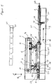
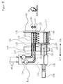
zeigt die Brettschichtholzpresse bestehend aus der umgebenden Konstruktion 1, woarauf der Einschubzylinder 2 befestigt ist. DerZylinder 3 ist durch denFlansch 18 mit demArretierungsbolzen 19 verbunden an deren Ende einKolben 20 axial in beidenPfeilrichtungen 11 und 12 mit Energie beaufschlagt werden kann, dadurch werden dieBolzen 19 in dieBohrungen 21 zur Arretierung bewegt. DieDruckeinheiten 4 und 5 bestehend aus denZylindern 6 + 7 welche auf dieDruckstücke 8 wirken. DieDruckeinheiten 4+5 können inPfeilrichtung 9+10 bewegbar sein durch die Rollen 17, welche durch denMitnehmer 13 mit dem Band 14 verbunden sind. Der Antrieb erfolgt über dasRad 15 und derUmlenkrolle 16.
Der Einschubzylinder 2 ist mit demheizbaren Druckstück 24 verbunden worauf Zwei Bretter mitLeim 23 inPfeilrichtung 12 von derAuflage 25 zumheizbaren Druckstück 24 gefördert werden. Die Verbindung 22 zwischen denDruckeinheiten 4+5 dient zur Kompensierung der Kräfte ausPfeilrichtung 9+10. DieHydraulikeitung 27. - Figur 2
mit denBrettern Pfeilrichtung 143 um 180 Grad mit denBrettern 144+140. DieMagazine 148 mitHalterungen 147 zur Aufnahme der Bretter. Der Quertransport in Pfeilrichtungen 141,142 . DiePfeilrichtung 142 zum Abtransport gemäß Figur 7 + 8. Figur 3
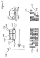
mit demBretterpaket 46, welches inPfeilrichtung 34 geschoben und über dieKante 35 vereinzelt wird. Derdrehbare Anschlag 36 verhindert ein mögliches Kippen. Dasangetriebene Band 42 fördert dieBretter Anschlag 33 desPreßschuhes 30 und betätigt denEndschalter 43, in der Position derPreßbahn 32, wo die mit Keilzinken und Leim versehenen Brettenden 47+48 endlos verbunden werden. DieKonstruktion 44 dient zur Aufnahme des Transportsystemes mit denAntriebsrollen 41 und desFörderbandes 42. DiePosition 31 der Preßbahn. DieFührungswelle 49 verbunden mit demDruckschuh 45 in derKonstruktion 44.Figur 4
zeigt einePlatte 50 aus beliebigem verleimfähigein Werkstoff, die mitLeim 52angegebenen Brettschichthölzer 51, welche inPfeilrichtung 53 und 54 mit derPlatte 50 verleimt werden. Der fertigverleimte Träger 55 mit ein- oderangebrachter Isolation 56.Figur 5
zeigt dasBrettschichtholz 60 und 61 mit demLeim 62 welcher inPfeilrichtung 63 +64 zusammengeleimt dasHohlkastenprofil 65 ergibt.- Die
Figur 6
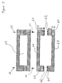
zeigtverleimtes Brettschichtholz 80 mitunterschiedlichen Breiten 81+82, welche durch ein Brett ohne Leim in derFuge 83+84 getrennte ist. - Figur 7
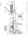
zeigt eine Transportanlage mit den 2Achsen 90+91, denMitnehmern 93+94 welche dieBretter 95 inPfeilrichtung 96 durch dieLeimangabe 97 schieben. Figur 8
zeigt das Brett 100, wird inPfeilrichtung 101 durch dieLeimangabe 102 geschoben. Die Leimangabe bestehend aus den Gehäuseteilen 103,104,105, dem Deckel 114 der inPfeilrichtung 107 und 108 bewegbar ist.Das Gehäuseteil 103 ist andem Ende 104 augespart zur besseren Dosierung desLeimes 117durch den Schieber 109.
Die Rollen 106 dienen zur Führung desSchiebers 109 inPfeilrichtung 110 + 111 welcher durch bekannte Artvon dem Antrieb 113 positionierbar ist zur Freigabe derÖffnungen 112, fürden Leim 117.Der Leim 117 bestehend aus seinen Komponenten 115 + 116 welche ausden Rohren 120 + 121 austreten und durch dieAussparungen am Ende 104auf das Brett 100 fließt, welches inPfeilrichtung 101 gefördert wird. Leim kann aus mehr als 2 Komponenten bestehen.Figur 9
zeigt die Leimangabe gem.Figur 8, dieRohre mit den Komponenten 115+116den Leim 117, der aufdem Brett 100 durch dieAussparungen 104 gelangte. Indie Rohre 120+121 sind Bohrungen 122,123 eingebracht, wo dieKomponennten 115+116 austreten.Die verschiebbaren Rohre 124 + 125 inPfeilrichtung 126 und 127 verschliessen dieBohrungen 122+123 durch den federndenDruck vom Zylinder 128 inPfeilrichtung 126.Der Zylinder 128ist am Gehäuse 104 durch die Kolbenstange 129 befestigt.Der Zylinderflansch 130 istmit der Konstruktion 132,den Führungswellen 133+134und dem Begrenzungsteil 135 des Leimbehälters bestehend aus den Teilen,103+104, verbunden.
Die Dosierpumpen 133+134 fördern mit stufenlos regelbarer Druck und Mengedie einzelnen Komponenten 115+116 in den Leimbehälter.Die Austrittsbohrungen 122+123der Rohre 120+121 sind so zueinander in Wirkstellung, daß ein Vermischen der einzelnen Komponenten 115+116 sofort nach dem Austritt erfolgt.- Figur 10
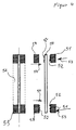
zeigt chematisch die zwei Einschubzylinder 160+161, mitLeim versehenden Brettern 162+163, dievorder Druckeinheit 165 und diehintere 166.Den Gegendruckzylinder 164.Die Kolbenstangen 167 aller Zylinder.Die Druckstücke 171 + 172, . Die angeleimten Bretter 168+169.Die Folie 170, Folie aufgerollt 173, amDruckstück befestigte Folie 174.Pfeilrichtung 175und 176.
- Figure 1
shows the glulam press consisting of the surrounding construction 1, on which the insertion cylinder 2 is attached. Thecylinder 3 is connected by theflange 18 to the lockingbolt 19 at the end of which apiston 20 can be axially energized in botharrow directions bolts 19 are moved into thebores 21 for locking. Theprinting units cylinders 6 + 7 which act on thepressure pieces 8. Theprinting units 4 + 5 can be moved in the direction of thearrow 9 + 10 by the rollers 17, which are connected to the belt 14 by thedriver 13. The drive takes place via thewheel 15 and thedeflection roller 16.
The insertion cylinder 2 is connected to theheatable pressure piece 24, whereupon two boards withglue 23 are conveyed in the direction ofarrow 12 from thesupport 25 to theheatable pressure piece 24. The connection 22 between thepressure units 4 + 5 serves to compensate the forces from thearrow direction 9 + 10. Thehydraulic line 27. - Figure 2
with theboards arrow 143 by 180 degrees with theboards 144 + 140. Themagazines 148 withholders 147 for holding the boards. The cross transport in the direction of thearrows arrow 142 for removal according to FIGS. 7 + 8. - Figure 3
with theboard package 46, which is pushed in the direction ofarrow 34 and separated over theedge 35. Therotatable stop 36 prevents possible tilting. The drivenbelt 42 conveys theboards stop 33 of thepress shoe 30 and actuates thelimit switch 43, in the position of thepress track 32, where the board ends 47 + 48 provided with finger joints and glue are connected endlessly. Theconstruction 44 serves to accommodate the transport system with thedrive rollers 41 and theconveyor belt 42. Theposition 31 of the press track. Theguide shaft 49 is connected to thepressure shoe 45 in theconstruction 44. - Figure 4
shows aplate 50 made of any glue-capable material, the glued laminatedtimber 51 indicated withglue 52, which are glued to theplate 50 in the direction of thearrows carrier 55 withinsulation 56 installed or attached. - Figure 5
shows theglulam glue 62 which glued together in the direction ofarrow 63 +64 results in thehollow box profile 65. - Figure 6
shows gluedglulam 80 withdifferent widths 81 + 82, which is separated by a board without glue in the joint 83 + 84. - Figure 7
shows a transport system with the 2axes 90 + 91, thedrivers 93 + 94 which push theboards 95 in the direction ofarrow 96 through theglue 97. - Figure 8
shows theboard 100, is pushed in the direction ofarrow 101 through theglue indication 102. The glue specification consisting of thehousing parts arrow housing part 103 is spared at theend 104 for better metering of theglue 117 by theslide 109.
Therollers 106 serve to guide theslide 109 in the direction of thearrow 110 + 111, which can be positioned by thedrive 113 in a known manner to open theopenings 112, for theglue 117. Theglue 117 consists of itscomponents 115 + 116, which consist of thetubes 120 + 121 emerge and flows through the cutouts at theend 104 onto theboard 100, which is conveyed in the direction ofarrow 101. Glue can consist of more than 2 components. - Figure 9
shows the glue specification acc. Figure 8, thetubes components 115 + 116, theglue 117, which got through therecesses 104 on theboard 100.Bores tubes 120 + 121, where thecomponents 115 + 116 emerge. Thedisplaceable tubes 124 + 125 in the direction of thearrows bores 122 + 123 by the resilient pressure from thecylinder 128 in the direction of thearrow 126. Thecylinder 128 is fastened to thehousing 104 by the piston rod 129. Thecylinder flange 130 is connected to theconstruction 132, theguide shafts 133 + 134 and the limitingpart 135 of the glue container consisting of the parts, 103 + 104.
The metering pumps 133 + 134 convey theindividual components 115 + 116 into the glue container with infinitely variable pressure and quantity. The outlet bores 122 + 123 of thetubes 120 + 121 are in the operative position with respect to one another in such a way that theindividual components 115 + 116 are mixed immediately after the outlet. - Figure 10
chemically shows the two insertion cylinders 160 + 161, with glue-providingboards 162 + 163, thefront pressure unit 165 and the rear 166. Theimpression cylinder 164. Thepiston rods 167 of all cylinders. Thepressure pieces 171 + 172,. The glued boards 168 + 169.Foil 170, foil rolled up 173,foil 174 attached to the pressure piece. Direction ofarrow
Die von der Keilzinkenpresse ankommenden Bretter aus dem Kanal 32 oder 31 werden vor der Leimangabe von der Transportanlage gem. Figur 7 übernommen und durch die Mitnehmer 93 oder 94 in Pfeilrichtung 96 durch die Leimangabe geschoben.
Entgegen der üblichen Art des Transportes durch Vorschubwalze. Die Leimangabe erfolgt gem. Figur 8. Durch stufenlos verengbare Schlitze 104 tritt der Leim aus, in Form einer Schnur gemäß Figur 8, 117.
Der Schieber 109 gibt die erforderliche Menge frei, durch die Bewegung in Pfeilrichtung 110 + 111. Der Antrieb 113 des Schiebers 109 verschließt die Öffnung 104 Wenn das nächste Brett zur Leimangabe gefördert wird, öffnet der Schieber 109. Der Leim besteht in der Regel aus zwei oder mehr Komponenten, welche durch die Bohrungen 122 + 123 der Rohre 120 + 121 zugeführt werden . Die Bohrungen sind vorteilhaft so angebracht, daß sich die zwei Komponenten 115 + 116 vermischen. Die Füllmenge des Leimes 117 kann durch nicht dargestellte Steuerungen überwacht werden. Die chemische Abbindung der zwei Komponenten kann beschleunigt werden, indem man einen oder beide Komponenten erwärmt. Die Leimangabe und Rohrleitungen können zu diesem Zweck beheizt werden. Die Leimangabe ist in der Breite stufenlos verstellbar und durch den federnden Druck von Zylinder 128 paßt sich die Leimangabe den Brettbreiten an und verhindert ein seitliches Austreten des Leimes.
Durch die Erwärmung des Leimes ist die Abbindung rasch und ein auslaufender Leim muß auf bekannte Art wieder schnell der Leimangabe zugeführt werden. Aus diesem Grund ist eine gute Abdichtung vorteilhaft. Die Dosierpumpen 133 + 134 fördern den Leim mit stufenlos regelbarem Druck und in dosierbaren Mengen durch die Rohre über die Bohrungen 122 + 123 in den Leimbehälter.
Die von der Leimangabe mit Leim versehenen Bretter 8 werden auf dem beheizbaren Druckstück 24 transportiert und durch den Einschubzylinder 2 in Pfeilrichtung 9 an den zu verleimenden Brettschichtholzträger gedrückt. Der Zylinder wird um die Holzstärke zurückgedrückt, weil der Gegendruck in Zylinder 3 durch die geringere Kolbenfläche bei Aufrechterhaltung der Barzahl niedriger ist. Das heizbare Druckstück 24 bleibt mit der Kraft des Zylinders 2 an der Rückseite des eingeschobenen Brettes 23 wirksam. Das heizbare Druckstück 24 überträgt die stufenlos regelbare Temperatur auf die Rückseite der Bretter 23, bis die nächsten zu verleimenden Bretter 23 auf der Auflage 25 bereitstehen zum Einschub in Pfeilrichtung 12. In der Regel beträgt der Rythmus von Brettern zu Brettern 30 -60 Sekunden. Diese Zeit reicht aus umd die chemische oder physikalische Abbindung des Leimes in der Leimfuge zu beschleunigen. Bevor der Zylinder 2 zurückfährt in Pfeilrichtung 10, tritt die Druckeinheit 4 mit dem Druckstück 8 in Pfeilrichtung 12 so in Wirkstellung, daß der Druck in dem zu verleimenden Brettschichtholz aufrecht erhalten bleibt. Der Zylinder 2 geht zurück, die Bretter 23 werden in Pfeilrichtung 12 auf das heizbare Druckstück 24 geschoben. Das Druckstück 24 in Pfeilrichtung 9 geschoben wird kraftschlüssig mit den vorhergehenden aufgeheizten Brettern 23, dann wird der Druck auf den Druckstück 8, der Druckeinheit 4 zurückgenommen. Gleichzeitig kann die in Zylinder 2 wirkende Energie in Pfeilrichtung 9, das Druckstück 8 des Gegendruckzylinders 3 um die Holzstärke der Bretter 23 zurückdrücken.
Wenn ein Brettschichtholzträger in der gewünschten Breite hergestellt werden soll, werden die letzten Bretter 23 einer Brettschichtholzträgerbreite nicht mit Leim angegeben. Der Kolbenhub des Zylinders 3 ist vorteilhaft so lang, wie die max. herzustellende Brettschichtholzbreite. Wenn eine Leerfuge das Ende der Breite anzeigt, dann, oder einige Einschübe später geht das Druckstück 8 durch den Hydraulikzylinder 7 der Druckeinheit 5 in Wirkstellung. Das Druckstück 8, wird durch den Zylinder 3 zurückgenommen und der verleimte Brettschichtholzträger wird angehoben in Pfeilrichtung 11 und auf bekannte Art zur Oberflächenbearbeitung abtransportiert. Zwischen den Druckeinheiten 4 + 5 wird der Druck aufrecht erhalten und die Verbindung 22 zwischen den Druckstücken 8 nimmt die wirkenden Kräfte in Pfeilrichtung 9 + 10 auf. Der Einschub der Bretter 23 kann weiter erfolgen, die regelbare Gegenkraft übernimmt die Druckeinheit 5 durch Friktion bis Zylinder 3 mit Druckstück in Wirkstellung ist. Die Friktion ist nur möglich, wenn der Leim im Brettschichtholzträger abgebunden hatt, wegen der möglichen Deformierung der einzelnen Bretter würde die Leimfuge zerstört. Deshalb muß anfänglich das Druckstück 8 des Zylinders 3 den Gegendruck übernehmen.Da die Brettschichtholzträger in unterchiedlichen Breiten gefertigt werden, wird die fahrbare Druckeinheit 5 durch den Mitnehmer 13 in Pfeilrichtung 10 oder 9 durch den Antrieb 15 in die erforderliche Position gebracht.
Auf der Konstruktion 1 ist die Lochschiene mit den Löchern 21 angebracht, wo die Druckluftzylinder 20 die Bolzen 19 im Vorderflansch 18 arretieren. Bei der Herstellung von breiten Trägern gemäß Figur 2 werden die von der Keilzinkenpresse ankommenden Bretter im Kanal 31 + 32 auf einmal durch die Leimangabe in die Presse geschoben. Das zweite Brettpaar wird durch die Wendevorrichtung gem.Figur 2 in der jeweiligen Pfeilrichtung 127 um 180 Grad gewendet oder die Bretter werden von den Magazinen 146 + 147 entsprechend abgerufen.The boards from
Contrary to the usual way of transport by feed roller. The glue is specified in accordance with Figure 8. The glue emerges through continuously narrowing
The
Due to the heating of the glue, the setting is quick and a leaking glue must be quickly fed back to the glue specification in a known manner. For this reason it is a good one Sealing advantageous. The metering pumps 133 + 134 convey the glue with infinitely variable pressure and in dosable quantities through the pipes through the
The
If a glulam beam is to be produced in the desired width, the
On the construction 1, the perforated rail with the
Bei der Herstellung von breiten Brettschichtholzträgern schreibt die DIN 1052 zwingend vor, daß die breiten Bretter in der Planfläche oben und unten eingeritzt werden, damit die Spannung im Holz aufgehoben wird. Bei der Verarbeitung von zwei oder mehreren Brettern unterschiedlicher Breite gemäß Figur 2 gibt es keine Spannungen in der Breite des Brettschichtholzträgers. Das Ritzen beidseitig entfällt! Durch die Zusammenstellung schmaler Hölzer zu einer Brettbreite können schmälere Bretter zu einem hochwertigen Erzeugnis verarbeitet werden, entgegen breiteren Brettern, mit dem hohen Aufwand. Brettschichtholzträger werden statisch nur in den Außenzonen voll beansprucht. Die Figur 4 + 5 zeigen mögliche Lösungen. Das T-Doppelprofil besteht aus dem Mittelteil 50 und dem Brettschichtholz 51 mit dem Leim 52, welches in Pfeilrichtung 53 + 54 zusammenverleimt wird. Die Verleimung geschieht in der Brettschichtholzprese gemäß Figur 1. Das heizbare Druckstück 24 dient als Positionieranschlag des Brettschichtholzes 55. Die Trägerbreite wird von dem Abstand 58, zwischen den Trägern 51 + 57 bestimmt. Die fahrbare Druckeinheit 5 ist aus diesem Grunde in Pfeilrichtung 9 +10 verschieb- und arretierbar.In the production of wide glulam beams, DIN 1052 stipulates that the wide boards are scored in the flat surface at the top and bottom so that the tension in the wood is released. When processing two or more boards of different widths according to FIG. 2, there are no tensions in the width of the glulam beam. There is no scratching on both sides! By combining narrow woods into a board width, narrower boards can be processed into a high-quality product, in contrast to wider boards, with the high effort. Glulam beams are only fully stressed statically in the outer zones. Figures 4 + 5 show possible solutions. The T-double profile consists of the
Bei der Herstellung von Profilen gemäß Figur 5 werden die Bretter 66 zuerst zu Brettschichtholz verleimt. Der Gegendruckzylinder 3 bleibt mit seinem Druckstück in Wirkstellung bis die schmäleren Hölzer 67 verleimt werden sollen. Zu diesem Zweck hat der Zylinder 2 einen verlängerten Kolbenhub in Pfeilrichtung 9 bis über das Ende des Preßschuhes 8. Die ersten drei schmäleren Bretter werden unter einem geringeren Druck in Pfeilrichtung 12 der ersten Druckeinheit verleimt. Beim Zylinder 3 wird der Ausgang der Hydraulikleitung 27 blockiert, bis die schmalen Bretter mit der Kante 26 übereinstimmen, danach erfolgt wieder die Aufrechterhaltung des Druckes durch das nicht dargestellte Überdruckventil des Zylinders 3. Das durch diese Art gewonnene Halbprofil 66+67 wird mit dem Leim 62 in der Brettschichtholzpresse gemäß Figur 1 mit der fahrbaren Druckeinheit 5 wieder verleimt. Zur schnellen Abbindung werden vorteilhaft ein oder mehrere Komponenten, die den Leim 117 ergeben aufgeheizt. Die Leimangabe erfogt vorteilhaft durch eine handelsübliche Leimangabe von Hand. Der Hohlraum kann auch teilweise zum Einbringen von Leerleitungen verwendet werde. Mit dem Verpressen kann vorteilhaft eine feuerhemmende Schicht aufgebracht werden.
Bei der Herstellung von Brettschichtholzträgern gibt es durch die unterschiedliche Breiten Probleme. Man muß die ganzen vorhandenen Preßen auf die unterschiedlichen Breiten umstellen, was einen hohen Arbeitsaufwand erfordert. Dies war Aufgabe der Erfindung, es mit einer neuen Brettschichtholzpresse zu lösen. Die Druckeinheiten können so in Wirkstellung gebracht werden,
daß unterschiedliche Breiten verarbeitet werden können. Figur 6 zeigt drei unterschiedliche Breiten eines Brettschichtholzträgers, der in der Figur 1 gefertigt wurde.When producing profiles according to FIG. 5, the
Due to the different widths, there are problems in the production of glulam beams. You have to change all the existing presses to different widths, which requires a lot of work. This was the object of the invention to solve it with a new glulam press. The pressure units can be brought into the active position
that different widths can be processed. FIG. 6 shows three different widths of a glulam beam which was manufactured in FIG. 1.
Die Druckeinheit 5 dient auch dazu, daß bei der Umstellung von einer Brettschichtholzbreite zu der anderen, der zweite Oberdruck durch Verschieben so in Wirkstellung kommt, damit ohne wesentliche Umstellzeit von einer zur anderen Brettbreite verleimt werden kann. Der Einschubzylinder 2 kann zu diesem Zweck einen längeren Hub besitzen, der über die Länge des wirkenden Druckschuhes 8 der oberen Druckeinheit 4 reicht, welche zur Erreichung der erforderlichen Positionen fahr- und justierbar sein kann. Zum vollständigen Entleeren der Brettschichtholzpresse gemäß Figur 1 kann ein Antrieb vorgesehen sein.
Der Druckschuh der Druckeinheit 4, kann durch das Teil 22 mit dem Druckschuh 5 verbunden sein, zur Kompensierung der Staukräfte aus der Pfeilrichtung 9 und 10.The
The pressure shoe of the
Der Einschubzylinder 2 ist in der Kolbenfläche größer ausgelegt als der den Verleimdruck bestimmende Gegendruckzylinder 3. Der Gegendruck wird durch ein Druckbegrenzungsventil eingestellt. Durch diese Ausführung benötigt man keine Steuerung und Überwachung des Verleimdruckes. Es wird nur die BAR-Zahl des Druckbegrenzungs - ventiles für die Berechnung des Verleimdruckes angewendet. Alle anderen Zylinder des Einschub- und Oberdruckes sind mindestens um die Kolbenfläche grösser, wie es der Reibungskoeffizient erfordert.The insertion cylinder 2 is designed larger in the piston area than the
Der Gegendruckzylinder 3 ist in bestimmten Abständen in den Bohrungen fixierbar. Der Kolbenhub beträgt vorteilhaft etwas mehr, als die mögliche Verleimbreite des Brettschichtholzträgers. Wenn ein Brett nicht mit Leim angegeben worden ist, gibt es eine Leerfuge, welche den zu verleimenden Brettschichtholzträger vom folgenden trennt. Hat die Leerfuge das Druckstück Passiert, dann wird die zweite Druckeinheit in Wirkung gebracht. Der Gegendruckzylinder wird auf der anderen Seite beaufschlagt und der Brettschichtholzträger durch ein eingebautes Rollensystem mit genügend Abstand von der Druckeinheit 5 in Längs- oder Querrichtung über die 4 - Seitenhobelmaschine in das Fertiglager oder zum Abbund transportiert. Der Gegendruckzylinder geht sofort nach dem Anheben des Schichtholzträgers wieder in Wirkstellung.Die Druckeinheit 5 hält in der Zwischenzeit den Verleimdruck aufrecht und kann über Friktion in bekannter Art das nächste Brett zum Verleimen in der Schichtholzpresse aufnehmen. Zur schnellen Abbindung des Leimes 52 in der Figur 4 und des Leimes 62 der Figur 5 können die Druckstücke 8 der Druckeinheiten 4 + 5 beheizbar sein. Bei Verleimung nach Figur 5 wird der Leim 62 nur auf der oberen Seite angegeben und die untere Seite kann so aufge-heizt sein durch die geheizten Druckstücke 8, daß nach Einbringen der oberen Seite und Wirkung des Preßdruckes der Leim in wenigen Minuten abgebunden ist. Bei Profil 4 kann auf die unten justierten Brettschichthölzer die heizbaren Druckstücke 8 wirken. Der Leim 52 kann auf die Platte 50 aufgetragen sein. Auf der Gegenseite wirkt der Preßdruck der Druckeinheiten 4+5 und heizt die Oberfläche auf, worauf das mit Leim angegebene Brettschichtholz wie bekannt geleimt wird.The
Die Brettschichtholzpresse Figur 1 besteht aus einer Vielzahl nebeneinander gereihten Pressen. In den Abständen können Hebe- und Transportvorrichtungen eingebracht sein zum Händling, Positionieren und Abtransport von dem Verleimten Brettschichtholz.
Die Brettschichtholzpresse kann horizontal oder vertikal in beliebigem Winkel erstellt werden. Bei kurzen Brettschichtholzträgern oder wenn nicht ausreichend Platz vorhanden ist zur Herstellung von Doppellängen, dann können gem. Figur 10, mehrere Brettschichthölzer hergestellt werden. Eine in der Fuge eingebrachte, mitlaufende Folie trennt die Brettschichthölzer. Der Einschub kann dann aus mehreren Hydraulikzylinder bestehen, welche nebeneinander arbeiten. Der Einschub in Preßposition erfolgt dann, wenn die mit Leim angegebene Bretter in Längsrichtung auf Wartestellung sind gem. Fig.10. Die Leimangabe kann direkt vor der Einlaufbahn der Presse positioniert sein. Diese Verleimart bietet sich besonders bei der Herstellung von schmalen Trägern an zur Auslastung der installierten Kräfte. Der Rythmus ist dan doppelt so lang, dadurch kann je nach Länge der Bretter das Druckstück bis zu 2 Minuten in Wirkstellung bleiben, die Abbindezeiten werden dann kürzer.The glulam press Figure 1 consists of a large number of presses arranged side by side. In the intervals lifting and transport devices can be introduced for handling, positioning and removal of the glued glulam.
The glulam press can be created horizontally or vertically at any angle. In the case of short glulam beams or if there is insufficient space for the production of double lengths, then according to Figure 10, several glulam can be produced. A running film inserted in the joint separates the glulam. The insert can then consist of several hydraulic cylinders that work side by side. The insertion in the pressing position takes place when the boards indicated with glue are on hold in the longitudinal direction acc. Fig. 10. The glue information can be positioned directly in front of the press infeed. This type of gluing is particularly useful in the manufacture of narrow beams to utilize the installed forces. The rhythm is then twice as long, which means that depending on the length of the boards, the pressure piece can remain in the active position for up to 2 minutes, the setting times are then shorter.
Zur Justierung des Gegendruckzylinders 3 in den Bohrungen 21 der einzelnen Positionen, sind einrastbare Bolzen 19 vorgesehen, die durch Hubzylinder 20 in Wirkung gebracht werden. Eine Justierung durch Friktion oder andere bekannte Art ist möglich.
Der Gegendruckzylinder 3 und die oberen Druckeinheiten 4+5 oder mehrere, können an Transportketten, Seilen oder Zahnstangen befestigt sein für das Erreichen erforderlicher Positionen.To adjust the
The
An Stelle von Zylindern die mit fluidischen Medien beaufschlagt werden, können Spindeln, Ketten oder sonstige geeignete Antriebe Verwendung finden.Instead of cylinders that are exposed to fluid media, spindles, chains or other suitable drives can be used.
Besuch der Messen Atlanta und Ligna Hannover, Gespräche mit führenden Fachleuten des deutschen, französichen und europäischen Holzleimbaus und den Ingenieuren der FMPA der TH Stuttgart-Vaihingen.Visited the trade fairs Atlanta and Ligna Hanover, talks with leading experts in German, French and European wood glue construction and the engineers of the FMPA of the TH Stuttgart-Vaihingen.
Holzzentralblatt, " Wir bauen mit Holz"
" Holz als Roh- und Werkstoff."Holzzentralblatt, "We build with wood"
"Wood as raw and material."
Prospekte und Besichtigung von Anlagen der Firmen Dimter GmbH 7918 Illertissen. Minda-Minden, GRECON Alsfeld/Hannover, Owe Petersen, Dänemark. Eisele Pressenbau.Brochures and inspection of systems from Dimter GmbH 7918 Illertissen. Minda-Minden, GRECON Alsfeld / Hanover, Owe Petersen, Denmark. Eisele press construction.
- 1.1.
- Konstruktionconstruction
- 2.2nd
- EinschubzylinderInsert cylinder
- 3.3rd
- Zylindercylinder
- 4.4th
- DruckeinheitPrinting unit
- 5.5.
- DruckeinheitPrinting unit
- 6.6.
- Zylindercylinder
- 7.7.
- Zylindercylinder
- 8.8th.
- DruckstückPressure piece
- 9.9.
- PfeilrichtungArrow direction
- 10.10th
- PfeilrichtungArrow direction
- 11.11.
- PfeilrichtungArrow direction
- 12.12th
- PfeilrichtungArrow direction
- 13.13.
- MitnehmerCarrier
- 14.14.
- Bandtape
- 15.15.
- Radwheel
- 16.16.
- UmlenkrollePulley
- 17.17th
- Rollenroll
- 18.18th
- Flanschflange
- 19.19th
- ArretierungsbolzenLocking bolt
- 20.20th
- Kolbenpiston
- 21.21.
- BohrungenHoles
- 22.22.
- Verbindungconnection
- 23.23.
- Leimglue
- 24.24th
- DruckstückPressure piece
- 25.25th
- AuflageEdition
- 26.26.
- KanteEdge
- 27.27.
- HydraulikleitungHydraulic line
- 28.28
- Heizungheater
- 29.29.
- ohnewithout
- 30.30th
- Anschlagattack
- 31.31
- Positionposition
- 32.32.
- PasitionPasition
- 33.33.
- Anschlagattack
- 34.34.
- PfeilrichtungArrow direction
- 35.35.
- KanteEdge
- 36.36.
- Anschlag drehbarStop rotatable
- 37.37.
- 38,39+40 Bretter38.39 + 40 boards
- 41.41.
- AntriebsrollenDrive rollers
- 42.42.
- FörderbandConveyor belt
- 43.43.
- EndschalterLimit switch
- 44.44.
- Konstruktionconstruction
- 45.45.
- DruckschuhPressure shoe
- 46.46.
- BretterpaketBoard package
- 47.+4847. + 48
- BrettendenBoard ends
- 49.49.
- FührungswelleGuide shaft
- 50.50.
- Platteplate
- 51.51.
- BrettschichthölzerGlulam
- 52.52.
- Leimglue
- 53. + 5453. + 54
- PfeilrichtungArrow direction
- 55.55.
- verleimter Trägerglued carrier
- 56.56.
- an-oder eingebrachte Isolationattached or inserted insulation
- 57.57.
- BrettschichtholzGlulam
- 58.59.58.59.
- ohnewithout
- 60.+6160. + 61
- BrettschichtholzGlulam
- 62.62.
- Leimglue
- 63. +6463. +64
- PfeilrichtungArrow direction
- 65.65.
- HohlkastenprofilBox girder profile
- 67,-68,6967, -68.69
- ohnewithout
- 70.70.
- FlachstahlFlat steel
- 71,71,
- Flachstehl verbundenFlat bar connected
- 72.72.
- tragendes Profilsupporting profile
- 73.73.
- Kolbenpiston
- 74. 75,74. 75,
- PfeilrichtungenArrow directions
- 80.80.
- BrettschichtholzGlulam
- 81.+8281. + 82
- unterschiedliche Breitendifferent widths
- 83.+8483. + 84
- Fuge ohne LeimJoint without glue
- 85.-8985.-89
- ohnewithout
- 90. + 9190. + 91
- Achsenaxes
- 93. + 9493. + 94
- MitnehmerCarrier
- 95.95.
- Bretterboards
- 96.96.
- PfeilrichtungArrow direction
- 97.97.
- LeimangabeGlue specification
- 98.+9998. + 99
- ohnewithout
- 100.100.
- Brettboard
- 101.101.
- PfeilrichtungArrow direction
- 102.102.
- LeimangabeGlue specification
- 103. 104. 105103. 104. 105
- Gehäusecasing
- 106.106.
- Rollenroll
- 107.+108107. + 108
- PfeilrichtungenArrow directions
- 109.109.
- SchieberSlider
- 110. 111.110, 111
- PfeilrichtungArrow direction
- 112.112.
- Öffnungenopenings
- 113.113.
- Antriebdrive
- 114.114.
- Deckelcover
- 115. 116.115. 116.
- KomponentenComponents
- 117.117.
- Leimglue
- 118.118.
- ohnewithout
- 119.119.
- ohnewithout
- 120. 121.120, 121
- RohreTube
- 122. 123122. 123
- BohrungenHoles
- 124. 125.124, 125.
- verschiebare Rohresliding pipes
- 126. 127.126, 127.
- PfeilrichtungenArrow directions
- 128.128.
- Zylindercylinder
- 129.129.
- KolbesntangeKolbesntange
- 130.130.
- ZylinderflanschCylinder flange
- 131.131.
- Kolbenpiston
- 132.132.
- Konstruktionconstruction
- 133. 134.133, 134
- FührungswellenGuide shafts
- 135.135.
- BegrenzungsteilLimiting part
- 136. 137.138.139.136.137.138.139.
- ohnewithout
- 140.140.
- PfeilrichtungArrow direction
- 141. 142 143.141, 142, 143.
- PeilrichtungenBearing directions
- 144. 145. 146.144, 145, 146.
- Bretterboards
- 147,148,149147,148,149
- ohnewithout
- 150. - 159150.- 159
- ohnewithout
- 160.+161160. + 161
- EinschubzylinderInsert cylinder
- 162+163162 + 163
- mit Leim angegebene Hölzer in EinschubpossitionWood specified with glue in insertion position
- 164.164.
- GegendruckzylinderImpression cylinder
- 165.165.
- vordere Druckeineheitfront printing unit
- 166.166.
- hintere Druckeinheitrear printing unit
- 167.167.
- KolbenstangePiston rod
- 168.+169168. + 169
- Bretter angeleimt zum BrettschichtholzBoards glued to the glulam
- 170.170.
- Foliefoil
- 171.172.171,172.
- DruckstückeThrust pieces
- 173.173.
- Folie aufgerolltFoil rolled up
- 174.174.
- Klemmstück mit Folie.Clamping piece with foil.
- 175 + 176175 + 176
- PfeilrichtungArrow direction
Claims (10)
Priority Applications (2)
| Application Number | Priority Date | Filing Date | Title |
|---|---|---|---|
| EP19930100716 EP0607480B1 (en) | 1993-01-18 | 1993-01-18 | Method and apparatus for producing laminated wooden beams and other wooden products from continuously finger jointed wooden boards |
| DE59307743T DE59307743D1 (en) | 1993-01-18 | 1993-01-18 | Processes and devices for the production of endless wood by finger jointing to glulam beams and other wood products |
Applications Claiming Priority (1)
| Application Number | Priority Date | Filing Date | Title |
|---|---|---|---|
| EP19930100716 EP0607480B1 (en) | 1993-01-18 | 1993-01-18 | Method and apparatus for producing laminated wooden beams and other wooden products from continuously finger jointed wooden boards |
Publications (2)
| Publication Number | Publication Date |
|---|---|
| EP0607480A1 true EP0607480A1 (en) | 1994-07-27 |
| EP0607480B1 EP0607480B1 (en) | 1997-11-26 |
Family
ID=8212541
Family Applications (1)
| Application Number | Title | Priority Date | Filing Date |
|---|---|---|---|
| EP19930100716 Expired - Lifetime EP0607480B1 (en) | 1993-01-18 | 1993-01-18 | Method and apparatus for producing laminated wooden beams and other wooden products from continuously finger jointed wooden boards |
Country Status (2)
| Country | Link |
|---|---|
| EP (1) | EP0607480B1 (en) |
| DE (1) | DE59307743D1 (en) |
Cited By (4)
| Publication number | Priority date | Publication date | Assignee | Title |
|---|---|---|---|---|
| EP1050636A3 (en) * | 1999-05-03 | 2001-10-04 | Riko Hise, D.O.O. | Modular wooden construction elements system with wooden frame elements and their manufacturing process |
| DE102013109206A1 (en) * | 2013-08-26 | 2015-02-26 | Ladenburger Gmbh | Process for the production of a construction lumber consisting of several lumbers and construction plywood |
| EP3208060A1 (en) * | 2016-02-16 | 2017-08-23 | Fill Gesellschaft m.b.H. | Method and device for manufacturing glued laminated timber |
| CN108117006A (en) * | 2018-02-02 | 2018-06-05 | 柳城县迪森人造板有限公司 | It is a kind of to put lifting platform for taking after plank gluing |
Citations (6)
| Publication number | Priority date | Publication date | Assignee | Title |
|---|---|---|---|---|
| US1901598A (en) * | 1930-05-28 | 1933-03-14 | John L Herzog Co | Machine for making panel core stock from mill clippings and the like |
| DE1991208U (en) * | 1964-10-23 | 1968-08-08 | Erwin Dimter, 7918 Illertissen | Cycle press |
| US4111247A (en) * | 1977-01-13 | 1978-09-05 | Weyerhaeuser Company | Log cutting and rejoining process for lumber manufacture |
| FR2503015A1 (en) * | 1981-04-02 | 1982-10-08 | Landex Ets | Roof timber jointing by microwave hardening of adhesive - applied to prepared ends and heated in multimode cavity |
| FR2624781A1 (en) * | 1987-12-22 | 1989-06-23 | Mathis Sa Ets Paul | Method for manufacturing shaped wooden elements, device for implementing this method and shaped elements thus obtained |
| EP0512503A2 (en) * | 1991-05-07 | 1992-11-11 | Reinhard Dimter | Finger jointing press and combined finger jointing milling, gluing and press installation |
-
1993
- 1993-01-18 DE DE59307743T patent/DE59307743D1/en not_active Expired - Fee Related
- 1993-01-18 EP EP19930100716 patent/EP0607480B1/en not_active Expired - Lifetime
Patent Citations (6)
| Publication number | Priority date | Publication date | Assignee | Title |
|---|---|---|---|---|
| US1901598A (en) * | 1930-05-28 | 1933-03-14 | John L Herzog Co | Machine for making panel core stock from mill clippings and the like |
| DE1991208U (en) * | 1964-10-23 | 1968-08-08 | Erwin Dimter, 7918 Illertissen | Cycle press |
| US4111247A (en) * | 1977-01-13 | 1978-09-05 | Weyerhaeuser Company | Log cutting and rejoining process for lumber manufacture |
| FR2503015A1 (en) * | 1981-04-02 | 1982-10-08 | Landex Ets | Roof timber jointing by microwave hardening of adhesive - applied to prepared ends and heated in multimode cavity |
| FR2624781A1 (en) * | 1987-12-22 | 1989-06-23 | Mathis Sa Ets Paul | Method for manufacturing shaped wooden elements, device for implementing this method and shaped elements thus obtained |
| EP0512503A2 (en) * | 1991-05-07 | 1992-11-11 | Reinhard Dimter | Finger jointing press and combined finger jointing milling, gluing and press installation |
Cited By (8)
| Publication number | Priority date | Publication date | Assignee | Title |
|---|---|---|---|---|
| EP1050636A3 (en) * | 1999-05-03 | 2001-10-04 | Riko Hise, D.O.O. | Modular wooden construction elements system with wooden frame elements and their manufacturing process |
| DE102013109206A1 (en) * | 2013-08-26 | 2015-02-26 | Ladenburger Gmbh | Process for the production of a construction lumber consisting of several lumbers and construction plywood |
| EP2842707A1 (en) | 2013-08-26 | 2015-03-04 | Ladenburger GmbH | Laminated wood beam and method for producing the same |
| EP3208060A1 (en) * | 2016-02-16 | 2017-08-23 | Fill Gesellschaft m.b.H. | Method and device for manufacturing glued laminated timber |
| AT518249A4 (en) * | 2016-02-16 | 2017-09-15 | Fill Gmbh | Method and device for producing glulam |
| AT518249B1 (en) * | 2016-02-16 | 2017-09-15 | Fill Gmbh | Method and device for producing glulam |
| CN108117006A (en) * | 2018-02-02 | 2018-06-05 | 柳城县迪森人造板有限公司 | It is a kind of to put lifting platform for taking after plank gluing |
| CN108117006B (en) * | 2018-02-02 | 2023-12-08 | 柳城县迪森人造板有限公司 | A put up elevating platform for after plank rubber coating |
Also Published As
| Publication number | Publication date |
|---|---|
| DE59307743D1 (en) | 1998-01-08 |
| EP0607480B1 (en) | 1997-11-26 |
Similar Documents
| Publication | Publication Date | Title |
|---|---|---|
| EP1892088B1 (en) | Method for manufacturing a lightweight building board | |
| EP1157794B1 (en) | Glueing machine for the manufacture of a plate from laminar wood elements | |
| EP0759839A1 (en) | Board, in particular moulded fibre board | |
| DE69917473T2 (en) | laminating | |
| EP0512503A2 (en) | Finger jointing press and combined finger jointing milling, gluing and press installation | |
| WO2005087464A1 (en) | Method and device for joining a sandwich plate batten frame | |
| EP0574388B1 (en) | Process and device for the manufacture of high-pressure laminates | |
| EP2025483B1 (en) | Press | |
| EP0607480A1 (en) | Method and apparatus for producing laminated wooden beams and other wooden products from continuously finger jointed wooden boards | |
| DE2318284A1 (en) | DEVICE FOR FEEDING CONTINUOUSLY WORKING COMPOSITE PRESSES | |
| DE3809989C2 (en) | Device for producing a plywood panel | |
| AT400691B (en) | PRODUCTION PLANT FOR THE PRODUCTION OF A RAW PROFILE FROM ROD OR BOARD SHAPED SLATS | |
| WO1990009263A1 (en) | Process and installation for manufacturing particle boards and the like | |
| DE19882772C2 (en) | Method and device for assembling and feeding veneer packs to a laminated veneer press | |
| DE102005061042A1 (en) | Cutting-to-length process for strings from extrusion press involves cutting several string parts into pallet blocks using saw blades moved transversely to pressing direction | |
| EP1262290B1 (en) | Sawing device for panels made of wood, of plastic material, or similar | |
| DE10225329A1 (en) | Dovetail joint gluing device for horizontal and vertical dovetailing has dovetailing machine working synchronously with connected longitudinal gluing machine | |
| AT504611B1 (en) | METHOD FOR PRODUCING COMPONENTS COMPRISING COMPONENTS CONTAINING WEDGE PENCIL COMPOSITIONS AND DEVICE FOR CARRYING OUT THIS METHOD | |
| EP3429811A1 (en) | Method for producing blocks of wooden parts which are placed against one another and glued together, and installation for carrying out the method | |
| DE4000804A1 (en) | Plank end dovetailing milling machine | |
| DE19810574B4 (en) | Device for actuating presses in clamping devices for the assembly of furniture | |
| EP0512300B1 (en) | Press, preferably veneer press | |
| DE651066C (en) | Process for the production of plywood panels in one operation | |
| DE102015206130B3 (en) | Method, apparatus and system for producing plywood | |
| DE1915462A1 (en) | Process and apparatus for the continuous production of wood laminate of the parquet type |
Legal Events
| Date | Code | Title | Description |
|---|---|---|---|
| PUAI | Public reference made under article 153(3) epc to a published international application that has entered the european phase |
Free format text: ORIGINAL CODE: 0009012 |
|
| AK | Designated contracting states |
Kind code of ref document: A1 Designated state(s): DE DK FR SE |
|
| RBV | Designated contracting states (corrected) |
Designated state(s): DE DK FR |
|
| 17P | Request for examination filed |
Effective date: 19941119 |
|
| 17Q | First examination report despatched |
Effective date: 19951221 |
|
| GRAG | Despatch of communication of intention to grant |
Free format text: ORIGINAL CODE: EPIDOS AGRA |
|
| GRAH | Despatch of communication of intention to grant a patent |
Free format text: ORIGINAL CODE: EPIDOS IGRA |
|
| GRAH | Despatch of communication of intention to grant a patent |
Free format text: ORIGINAL CODE: EPIDOS IGRA |
|
| GRAA | (expected) grant |
Free format text: ORIGINAL CODE: 0009210 |
|
| AK | Designated contracting states |
Kind code of ref document: B1 Designated state(s): DE DK FR |
|
| PG25 | Lapsed in a contracting state [announced via postgrant information from national office to epo] |
Ref country code: DK Free format text: LAPSE BECAUSE OF NON-PAYMENT OF DUE FEES Effective date: 19971126 |
|
| REF | Corresponds to: |
Ref document number: 59307743 Country of ref document: DE Date of ref document: 19980108 |
|
| ET | Fr: translation filed | ||
| PLBE | No opposition filed within time limit |
Free format text: ORIGINAL CODE: 0009261 |
|
| STAA | Information on the status of an ep patent application or granted ep patent |
Free format text: STATUS: NO OPPOSITION FILED WITHIN TIME LIMIT |
|
| 26N | No opposition filed | ||
| PGFP | Annual fee paid to national office [announced via postgrant information from national office to epo] |
Ref country code: FR Payment date: 19990427 Year of fee payment: 7 |
|
| PG25 | Lapsed in a contracting state [announced via postgrant information from national office to epo] |
Ref country code: FR Free format text: LAPSE BECAUSE OF NON-PAYMENT OF DUE FEES Effective date: 20000929 |
|
| REG | Reference to a national code |
Ref country code: FR Ref legal event code: ST |
|
| PGFP | Annual fee paid to national office [announced via postgrant information from national office to epo] |
Ref country code: DE Payment date: 20030131 Year of fee payment: 11 |
|
| PG25 | Lapsed in a contracting state [announced via postgrant information from national office to epo] |
Ref country code: DE Free format text: LAPSE BECAUSE OF NON-PAYMENT OF DUE FEES Effective date: 20040803 |