EP0606488B1 - Control method for spot welding robot - Google Patents
Control method for spot welding robot Download PDFInfo
- Publication number
- EP0606488B1 EP0606488B1 EP93914941A EP93914941A EP0606488B1 EP 0606488 B1 EP0606488 B1 EP 0606488B1 EP 93914941 A EP93914941 A EP 93914941A EP 93914941 A EP93914941 A EP 93914941A EP 0606488 B1 EP0606488 B1 EP 0606488B1
- Authority
- EP
- European Patent Office
- Prior art keywords
- pressurization
- time
- robot
- spot welding
- command
- Prior art date
- Legal status (The legal status is an assumption and is not a legal conclusion. Google has not performed a legal analysis and makes no representation as to the accuracy of the status listed.)
- Expired - Lifetime
Links
Images

Classifications
-
- B—PERFORMING OPERATIONS; TRANSPORTING
- B23—MACHINE TOOLS; METAL-WORKING NOT OTHERWISE PROVIDED FOR
- B23K—SOLDERING OR UNSOLDERING; WELDING; CLADDING OR PLATING BY SOLDERING OR WELDING; CUTTING BY APPLYING HEAT LOCALLY, e.g. FLAME CUTTING; WORKING BY LASER BEAM
- B23K11/00—Resistance welding; Severing by resistance heating
- B23K11/24—Electric supply or control circuits therefor
- B23K11/25—Monitoring devices
- B23K11/252—Monitoring devices using digital means
- B23K11/253—Monitoring devices using digital means the measured parameter being a displacement or a position
-
- B—PERFORMING OPERATIONS; TRANSPORTING
- B23—MACHINE TOOLS; METAL-WORKING NOT OTHERWISE PROVIDED FOR
- B23K—SOLDERING OR UNSOLDERING; WELDING; CLADDING OR PLATING BY SOLDERING OR WELDING; CUTTING BY APPLYING HEAT LOCALLY, e.g. FLAME CUTTING; WORKING BY LASER BEAM
- B23K11/00—Resistance welding; Severing by resistance heating
- B23K11/10—Spot welding; Stitch welding
- B23K11/11—Spot welding
- B23K11/115—Spot welding by means of two electrodes placed opposite one another on both sides of the welded parts
-
- B—PERFORMING OPERATIONS; TRANSPORTING
- B23—MACHINE TOOLS; METAL-WORKING NOT OTHERWISE PROVIDED FOR
- B23K—SOLDERING OR UNSOLDERING; WELDING; CLADDING OR PLATING BY SOLDERING OR WELDING; CUTTING BY APPLYING HEAT LOCALLY, e.g. FLAME CUTTING; WORKING BY LASER BEAM
- B23K11/00—Resistance welding; Severing by resistance heating
- B23K11/24—Electric supply or control circuits therefor
- B23K11/25—Monitoring devices
- B23K11/252—Monitoring devices using digital means
Definitions
- the present invention relates to an improvement in a method of controlling a spot welding robot, more particularly, to a control method ensuring a correct timing to issue a pressurization command to a welding gun.
- a first is a method comprising the steps of, in the mentioned order, (1) detecting the completion of a positioning action for a spot welding; (2) issuing a gun pressurization command to a spot welding gun; (3) detecting the input of a pressurization completion signal from the spot welding gun; and (4) performing a welding operation by the spot welding gun through the issue of the welding command.
- a second is a method comprising the steps of (1) issuing a gun pressurization command before detecting the completion of the positioning action for the spot welding (that is, during the positioning action for the spot welding; (2) detecting the input of a gun pressurization completion signal; (3) issuing a welding command to execute a welding operation by a spot welding gun.
- a gun pressurization command designated at (b) is a pressurization command for allowing the spot welding gun to be ready for a welding operation
- a welding command designated at (c) is a command for allowing the spot welding gun to perform an actual welding action based on welding conditions such as current and voltage to be applied which are preset in a robot controller. Both the commands are sent to the spot welding gun from the robot controller.
- a welding completion signal designated at (d) is a confirmation signal which is sent to the robot controller from the robot welding gun at the point when the welding operation has been fully completed; and a pressurization completion signal designated at (e) is a confirmation signal to be outputted to the robot controller by the spot welding gun for which completion of pressurization has been detected.
- the gun pressurization command is issued in advance (at time t1), and the input of the pressurization completion signal is detected (at time t3) to issue the welding command for welding operation.
- a positioning action for the next welding point will be started after a predetermined standby period (until the time t5).
- the time period between the time at which the pressurisation command has been issued to the relevant gun, and the time at which the pressurization completion signal is obtained following the completion of the pressurization is estimated and stored previously in the controller as the expected time T0 required for the pressurization.
- the movement time T (a time elapsed from time t0 to time t2) required for the positioning of the robot will be calculated based on the distance L to the target position and the data of commanded moving speed F of the robot.
- T-T0 a difference between the movement time T and the expected time T0 required for pressurization which has been stored in the robot controller.
- the value of the expected time T0 required for pressurization to be set in the robot controller has been exclusively determined depending on the experience of the user. This may bring about a problem such that, even though the expected time required for pressurization is estimated to be T0, as shown in Fig 5, for example, if the value T0 is smaller than the actual time T0' (T0 ⁇ T0') required for pressurization, then the welding command is not permitted to be issued until a certain time has elapsed from the time of completion of the positioning action (time t2) of the robot, causing problems such as prolongation of total operating time.
- the welding command will be issued untimely prior to the completion of the positioning action of the robot to start the welding operation, which may hinder satisfactory performance of welding operation.
- the object of the present invention is to provide a method of controlling a spot welding robot, capable of eliminating or reducing a standby time which is wasteful for a robot in carrying out a welding operation in response to a command, and prohibiting an output of a welding command previous to the completion of the positioning action of the robot, therefore enabling an effective and secure spot welding operation.
- the present invention comprises the steps of measuring by a robot controller a time which has elapsed until the robot controller receives a pressurization completion signal from a spot welding gun after the robot controller issues a pressurization command to the spot welding gun; setting and storing the thus measured value into a memory of the robot controller as a time required for pressurization for the spot welding gun; when controlling a robot by the robot controller to execute a spot welding operation by the spot welding gun, calculating a movement time required for the completion of the positioning of the robot after the start thereof; comparing the time required for pressurization with the movement time; if the time required for pressurization is equal to or more than the movement time, causing the robot controller to issue a gun pressurization command to the welding gun simultaneously with the issue of the robot positioning command; and, if the time required for pressurization is less than the movement time, causing the robot controller to issue a gun pressurization command to the welding gun at the point when a time obtained by subtracting the elapsed time from the movement time after issuing the
- the method further comprises the steps of executing plural number of times of measurement of the elapsed time for the same gun; finding a mean value of the actually measured values; and storing the mean value into the memory as a time required for pressurization for the welding gun.
- the time required for pressurization to be stored into the memory of the robot controller is the number of processing periods obtained by dividing the movement command to the robot by the predetermined processing cycle.
- Fig. 1 is a block diagram schematically showing an example of an industrial robot equipped with a spot welding gun, that is, a spot welding robot.
- the spot welding robot generally comprises a robot controller 1, a robot body 2, and a robot welding gun 3 attached to a wrist or the like of the robot body 2.
- the robot controller 1 includes a CPU or a microprocessor 11.
- a ROM 12 for storing, e.g., a control program
- a RAM 16 for use in, e.g., temporarily storing data
- a nonvolatile memory 17 which, e.g., stores a time T0 needed to complete a pressurization of the spot welding gun 3 after issuing a gun pressurization command to the spot welding gun 3 and stores an operation program prepared by, e.g., a teaching operation
- a teaching console panel 13 for teaching an action to the robot
- a console panel 14 for a shaft controller 18 for driving and controlling shafts of the robot body 2 by way of a servo circuit 20; an input/output interface 19 and the like.
- the input/output interface 19 is connected to the spot welding gun 3 through a signal line which is used for the input/output of, e.g., the gun pressurization command, a welding command, a pressurization completion signal, and a welding completion signal.
- a conventional time-sharing processing method is employed for the driving and control of the robot body 2 by means of the robot controller 1. More specifically, as shown in Fig. 6, a combination of the following processings is repeatedly executed in every predetermined processing cycle iTP; a processing common to all the shafts for calculating the interpolation command value or the like, as is represented by section (a) in the diagram; a shaft interpolation processing for each shaft based on the interpolation command value, corresponding to sections (b)-(h); a program editing which is not directly relating to the drive and control of individual shafts, and a background processing for detecting key operations including a teaching operation, on the teaching console panel 13 and the console panel 14.
- Each of the above processings is performed in order at a period ⁇ iTP.
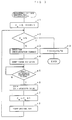
- Fig. 3 is a flowchart functionally showing an outline of a "processing for measuring a time required for pressurization” to be executed in the above-described background processing correspondingly to a command operation of the console panel 14 by the operator, though various interrupt processings and the like are omitted.
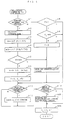
- Fig. 4 is a flowchart showing an outline of a "processing for issuing a pressurization command” which is to be repeatedly carried out in every predetermined processing cycle (iTP) together with the above-mentioned processing common to all the shafts.
- Fig. 2 is a timing chart showing the input/output of signals between the robot controller 1 and the spot welding gun 3 correspondingly to an action of the robot body 2 during the welding operation. Referring to these drawings, there will be described hereinbelow a method of controlling the spot welding robot in accordance with this embodiment.
- the operator When performing a welding operation by the spot welding robot for the first time or when newly performing a welding operation after replacing the spot welding gun 3 of the robot body 2 with another one, the operator operates a key on the console panel 14 to cause the microprocessor 11 of the robot controller 1 to execute the "processing for measuring a time required for pressurization". Prior to this execution the number of times N which the measurement is executed is set in the robot controller 1.
- the microprocessor 11 initializes to 0 both the value of a counter Cm storing the number of times of measurement and the value of a register SUM integrating and storing the sum total of measured values (Step a1). Next, the microprocessor 11 determines whether or not the value of the counter Cm has reached the preset number of times N of the measurement (Step a2).
- Step a2 In the stage of being ready for a first measurement after initializing the values of both the counter Cm and the register SUM, and in the stage where the number of times of measurement has not yet reached N, the results of judgment in Step a2 becomes NO (N).
- the microprocessor 11 sends a gun pressurization command to the spot welding gun 3 via the input/output interface 19 (Step a3), starts measuring the time elapsed immediately after the initialization of the timer (Step a4), and enters the state waiting (the state standing by) for the input of the pressurization completion signal from the spot welding gun 3 (Step a5).
- the robot welding gun 3 puts an actuator such as an air cylinder in motion to start a pressurizing action.
- the spot welding gun 3 sends a pressurization completion signal to the robot controller 1 via the input/output interface 19.
- the microprocessor 11 waiting for the input of the pressurization completion signals from the spot welding gun 3 detects through the judgment processing in Step a5 the entry of the pressurization completion signal, and immediately stop the action of the timer. Then, the measured value of the timer obtained at that time is added to the value being already stored in the register SUM (Step a6), and increments by 1 the value of the counter Cm which integrates and stores the number of times of measurement (Step a7). Thereafter, the microprocessor 11 issues a reset command to the spot welding gun 3 and confirms the return to the initial state of the spot welding gun 3 (Step a8), and again advances to the judgment processing in Step a2.
- the microprocessor 11 repeatedly executes the processings from Step a2 to Step a8 in the same manner as the above until the value of the counter Cm reaches the preset number of times N of measurement and the judgment in Step a2 results in YES (Y), and then advances to the processing in Step a9 with the sum total of the results of measurement kept within the register SUM.
- the sum total of the measurement results is divided by the number of times N of measurement, and the resultant value (or mean measured value) is stored in a time required storing register TO of the nonvolatile memory 17.
- This mean measured value defines the time required for the pressurization. In other words, the time needed to complete the pressurization of the spot welding gun 3 after issuing the gun pressurization command to the spot welding gun 3 is determined based on the results of actual measurement.
- the microprocessor 11 When an operation program previously created for the spot welding is selected from the nonvolatile memory 17 to start a playback action after storing into the nonvolatile memory 17 thus obtained actual mean measured value To of the time required for the pressurization, the microprocessor 11 repeatedly executes a "pressurization command output processing" as shown in Fig. 4, along with the processing common to the all shafts, for each of the predetermined processing cycle iTP.
- the microprocessor 11 after having calculated an interpolation command value and the like for each shaft based on the operation program by the conventional processing common to all the shafts to advance to the "pressurization command output processing", first determines whether or not a movement command for the spot welding as an object of the calculation of the interpolation command value has "newly” been read in the common processing to all shafts" (see Fig. 6(a)) of the present cycle (Step b1).
- the microprocessor 11 calculates a movement time T, required for the robot body 2 to complete the positioning at a welding point after starting its movement, based on distance of movement L and a commanded moving speed F specified by this movement command (Step b2). Then, the value T is divided by the processing cycle iTP into an integer to find the number of times N of executing the shaft interpolation processing for each shaft required for completing the positioning after the start of the movement. Thus obtained N is stored in a register N (Step b3).
- the microprocessor 11 reads out from the nonvolatile memory 17 (the storage register TO) a time T0 required for the pressurization of the spot welding gun 3, and divides the value T0 by the processing cycle iTP into an integer to thereby find the number of times N0 of the shaft interpolation processing for each shaft to be executed during the time required T0.
- T0 is stored within a register N0 (Step b4).
- the microprocessor 11 compares the number of times N of the shaft interpolation processing to be executed for each shaft corresponding to the movement time T needed to complete the positioning with the number of times N0 of the shaft interpolation processing required for each shaft corresponding to the required pressurization time T0 for the pressurization of the spot welding gun 3 (Step b5).
- the number of times N0 of the shaft interpolation processing for each shaft corresponding to the time required T0 for pressurization is subtracted from the number of times N of the shaft interpolation processing for each shaft corresponding to the movement time T to obtain the number of times to be executed Nd of the shaft interpolation processing for each shaft which corresponds to the waiting time [T - T0] from the point of starting the movement of the robot body 2 to the point of issuing the gun pressurization command, and the value thus obtained is set in the register N for updating (Step b6).
- the value of a counter Ci which stores the number of times of the shaft interpolation processing for each shaft, is initialized to 0, thereby setting a pressurization command output standby flag F (Step b7).
- Step b12 the microprocessor 11 determines whether or not it receives a pressurization completion signal from the spot welding gun 3 (Step b12). In the state where a gun pressurization command has not been issued yet though the movement of the robot body started, or where the spot welding gun 3 has not yet issued the gun pressurization completion command though a gun pressurization command was issued, the determination in Step b12 will result in NO (N).
- the microprocessor 11 with the determination of NO in Step b12, further determines whether or not it receives the welding completion signal from the spot welding gun 3 (Step b14).
- Step b16 In the state of waiting for a welding command or in the state where the welding is in progress and thus has not been completed, the determination will be NO (N), and the microprocessor 11 increments by one the value of the counter Ci, which stores the number of times of the shaft interpolation processing for each shaft, to complete the "pressurization command output processing" in the present processing cycle (Step b16).
- the shaft interpolation processing is executed sequentially for each shaft in each subsequent period ⁇ iTP (see Fig. 6(b) to (h)) to start the positioning action of the robot body 2, based on the interpolation command value for each shaft of the robot which was calculated in the processing common to all the shafts (see Fig. 6(a)) in each period of ⁇ iTP in the present processing cycle (iTP).
- Step b1 determines whether or not the pressurization command output waiting flag F is set (Step b8). However, since the pressurization command output waiting flag F remains set to 1 without having been reset later, the determination in Step b8 will result in YES (Y).
- the microprocessor 11 determines whether or not the value of the counter Ci, which stores the number of times of the shaft interpolation processing for each shaft (in Step b16), has reached the value N stored within the register N (in Step b6), that is, determines whether or not the shaft interpolation processing for each shaft has been repeatedly executed in response to the number of times of the shaft interpolation processing for each shaft corresponding to the waiting time [T-T0] from the point of starting the movement of the robot body 2 to the point of issuing the gun pressurization command (Step b9).
- Step b16 If the value of the counter Ci has not yet reached the value of the register N, and therefore, if the present processing cycle (iTP) has not yet reached the cycle to issue the gun pressurization command, the microprocessor 11 executes determination processing in Steps b12 and b14, which will both result in NO (N), and then increments by one the value of the counter Ci, which stores the number of times of the shaft interpolating processing for each shaft, to end the "pressurization command output processing" in the present processing cycle (Step b16).
- the microprocessor 11 sequentially executes the shaft interpolation processing in each period ⁇ iTP in the same processing cycle (iTP) (see Fig. 6 (b) to Fig. 6 (h)), and continuously performs the positioning action of the robot body. Since the interpolation processing for each shaft is carried out once in each processing period ⁇ iTP in the same processing cycle, the value of the counter Ci to be incremented for each processing cycle indicates the same value as the number of times of the shaft interpolation processing for each shaft.
- the microprocessor 11 repeatedly performs the processings of Steps b1, b8, b9, b12, b14 and b16 in the "pressurization command output processing" for each processing cycle (iTP) in the same manner as the above, and waits for the time when the value of the counter Ci reaches the value of the register N.
- Step b9 the microprocessor 11 resets the pressurization command output standby flag F (Step b10), and, as shown in Fig. 2, issues the gun pressurization command to the spot welding gun 3 to start the pressurizing action of the spot welding gun 3 (Step b11).
- Steps b12, b14 and b 16 After starting the pressurizing action of the spot welding gun 3, the microprocessor 11 executes the processing of Steps b12, b14 and b 16 in the same manner as the above.
- the pressurization command output processing in the processing cycle succeeding this processing cycle (iTP)
- the processing cycle (iTP) is executed repeatedly by the number of times of execution corresponding to the time required T0 for the pressurization of the spot welding gun 3 with the count starting from the point of issuing the gun pressurization command.
- the processing cycle (iTP) is executed repeatedly by the number of times of execution corresponding to the time required T0 for the pressurization of the spot welding gun 3 with the count starting from the point of issuing the gun pressurization command.
- the pressurization of the spot welding gun 3 is also completed, and the sport welding gun issues the pressurization completion signal to the robot controller 1 (Fig. 2(e)).
- the microprocessor 11 which is in the process of repeatedly executing the processing of the Steps b1, b8, b12, b14 and b16 in the "pressurization command output processing" during the processing cycle (iTP), detects the input of the pressurization completion signal in the determination processing of the Step b12, and issues the welding command to the spot welding gun 3 (Fig. 2(c)) to start the actual welding action (Step b13). Subsequently, in the same manner as the above, after executing the processing of Steps b14 and b16, the microprocessor 11 repeatedly executes the processing of Steps b1, b8, b12, b14 and b16 in the "pressurization command output processing" during the subsequent processing cycle (iTP).
- the microprocessor 11 which executes the processing of Steps b1, b8, b12, b14 and b16, detects the input of the welding completion signal though the determination processing in Step b14 to stop the output of the gun pressurization command and welding command (Figs. 2(b) and 2(c)), and returns the spot welding gun 3 to the initialized state (Step b15).
- Step b16 After executing the processing of Step b16 in the same manner as the above, there will be repeatedly executed the processing of Steps b1, b8, b12, and b16 in the "pressurization command output processing" during the subsequent processing cycle (iTP).
- the microprocessor 11 detects it through the processing of Step b1, and repeatedly executes the "pressurization command output processing" in the same manner as the above.
- Step b5 results in NO in the "pressurization command output processing" during the processing cycle (iTP) at the point when the movement command for the spot welding as an object for the calculation of the interpolation command value is newly read, that is, where it is determined that the required time T0 for the pressurization is longer than the movement time T needed to complete the positioning
- the microprocessor 11 issues the gun pressurization command immediately without setting the pressurization command output standby flag F after executing the determination processing of Step b5 (Step b11). Then the microprocessor 11 repeatedly executes the processing of Steps b1, b8, b12, b14 and b16 to wait for the input of the pressurization completion signal from the spot welding gun 3.
- Described in the foregoing as an embodiment of the present invention are the case where the time T0 required for the pressurization is to be measured and stored in the nonvolatile memory 17 only when the welding operation by the spot welding gun is executed for the first time by the spot welding robot or only when the welding operation is executed after changing the spot welding gun of the robot body 2.
- the value of the time T0 required for pressurization may be measured actually each time the welding operation is carried out so that this measured value may be stored in the nonvolatile memory 17 as the latest required pressurization time T0 for updating in order that the "pressurization command output processing" can be executed based on the latest required pressurization time T0 as illustrated in Fig. 4.
- the actual measurement of the value of the time T0 required for pressurization for each of the welding operation can be implemented, for example, by starting the measurement of time by the timer or the count of the processing cycle (iTP) simultaneously with the execution of the processing of Step b11 in the "pressurization command output processing", while by stopping the measurement of time by the timer or the count of the processing cycle iTP at the point when the determination in Step b12 results in YES (Y), and successively storing into the nonvolatile memory 17 for updating the value of the time required for pressurization which was calculated based on the time measured by the timer or the value of count of the processing cycles (iTP).
- an ordinary computer application techniques might allow the execution of the "pressurization command output processing" as shown in Fig. 4 by calculating the mean value of the time required for pressurization every time a welding operation is carried out.
Landscapes
- Engineering & Computer Science (AREA)
- Mechanical Engineering (AREA)
- Resistance Welding (AREA)
- Manipulator (AREA)
Applications Claiming Priority (3)
| Application Number | Priority Date | Filing Date | Title |
|---|---|---|---|
| JP20011192A JP3207533B2 (ja) | 1992-07-06 | 1992-07-06 | スポット溶接用制御装置及び制御方法 |
| JP200111/92 | 1992-07-06 | ||
| PCT/JP1993/000905 WO1994001237A1 (en) | 1992-07-06 | 1993-07-01 | Control method for spot welding robot |
Publications (3)
| Publication Number | Publication Date |
|---|---|
| EP0606488A1 EP0606488A1 (en) | 1994-07-20 |
| EP0606488A4 EP0606488A4 (en) | 1994-11-30 |
| EP0606488B1 true EP0606488B1 (en) | 1997-01-15 |
Family
ID=16419016
Family Applications (1)
| Application Number | Title | Priority Date | Filing Date |
|---|---|---|---|
| EP93914941A Expired - Lifetime EP0606488B1 (en) | 1992-07-06 | 1993-07-01 | Control method for spot welding robot |
Country Status (6)
| Country | Link |
|---|---|
| US (1) | US5449875A (ja) |
| EP (1) | EP0606488B1 (ja) |
| JP (1) | JP3207533B2 (ja) |
| KR (2) | KR940702424A (ja) |
| DE (1) | DE69307484T2 (ja) |
| WO (1) | WO1994001237A1 (ja) |
Families Citing this family (12)
| Publication number | Priority date | Publication date | Assignee | Title |
|---|---|---|---|---|
| JPH0810949A (ja) * | 1994-06-23 | 1996-01-16 | Fanuc Ltd | 多層盛り溶接における溶接ロボットシステムの制御方法 |
| JP3406080B2 (ja) * | 1994-08-24 | 2003-05-12 | ファナック株式会社 | 溶接ロボットシステムにおける溶接装置の割当使用方法 |
| JPH08278161A (ja) * | 1995-02-10 | 1996-10-22 | Ckd Corp | シリンダ装置 |
| JP3668325B2 (ja) * | 1996-06-13 | 2005-07-06 | 川崎重工業株式会社 | 溶接ガンの加圧制御方法 |
| GB2315135B (en) * | 1996-07-10 | 2000-12-06 | Honda Motor Co Ltd | Control apparatus for welding robot |
| US5988486A (en) * | 1997-03-11 | 1999-11-23 | Honda Giken Kogyo Kabushiki Kaisha | Method of controlling electrode force of spot welding gun |
| US5898285A (en) * | 1997-03-11 | 1999-04-27 | Honda Giken Kogyo Kabushiki Kaisha | Method of teaching welding robot |
| JP2941782B1 (ja) * | 1998-05-11 | 1999-08-30 | 川崎重工業株式会社 | スポット溶接ロボットの制御方法および制御装置 |
| JP4713030B2 (ja) * | 2001-09-18 | 2011-06-29 | 本田技研工業株式会社 | エンドエフェクタの開度設定方法 |
| JP2010094787A (ja) * | 2008-10-17 | 2010-04-30 | Yamaha Motor Co Ltd | 電動グリッパを装備するロボットおよび電動グリッパの制御方法 |
| JP6822881B2 (ja) * | 2017-03-27 | 2021-01-27 | 株式会社神戸製鋼所 | 積層造形物の製造方法及び製造システム |
| JP6572281B2 (ja) * | 2017-10-06 | 2019-09-04 | ファナック株式会社 | スポット溶接システム |
Family Cites Families (4)
| Publication number | Priority date | Publication date | Assignee | Title |
|---|---|---|---|---|
| JPS6380982A (ja) * | 1986-09-22 | 1988-04-11 | Ohara Kinzoku Kogyo Kk | 溶接機用制御装置 |
| JPH01215472A (ja) * | 1988-02-24 | 1989-08-29 | Honda Motor Co Ltd | 自動溶接機の制御方法 |
| JPH0533968A (ja) * | 1991-07-26 | 1993-02-09 | Sharp Corp | 空気調和機 |
| JP2506402Y2 (ja) * | 1991-10-11 | 1996-08-07 | 川崎重工業株式会社 | スポット溶接ロボット用制御装置 |
-
1992
- 1992-07-06 JP JP20011192A patent/JP3207533B2/ja not_active Expired - Fee Related
-
1993
- 1993-07-01 EP EP93914941A patent/EP0606488B1/en not_active Expired - Lifetime
- 1993-07-01 US US08/199,277 patent/US5449875A/en not_active Expired - Lifetime
- 1993-07-01 WO PCT/JP1993/000905 patent/WO1994001237A1/ja active IP Right Grant
- 1993-07-01 DE DE69307484T patent/DE69307484T2/de not_active Expired - Fee Related
- 1993-07-01 KR KR1019940700727A patent/KR940702424A/ko active IP Right Grant
- 1993-07-01 KR KR1019940700727A patent/KR970005924B1/ko active
Also Published As
| Publication number | Publication date |
|---|---|
| JPH0623561A (ja) | 1994-02-01 |
| KR970005924B1 (ko) | 1997-04-22 |
| WO1994001237A1 (en) | 1994-01-20 |
| JP3207533B2 (ja) | 2001-09-10 |
| EP0606488A4 (en) | 1994-11-30 |
| DE69307484D1 (de) | 1997-02-27 |
| DE69307484T2 (de) | 1997-05-15 |
| US5449875A (en) | 1995-09-12 |
| KR940702424A (ko) | 1994-08-20 |
| EP0606488A1 (en) | 1994-07-20 |
Similar Documents
| Publication | Publication Date | Title |
|---|---|---|
| EP0606488B1 (en) | Control method for spot welding robot | |
| US6903527B2 (en) | Servo controller | |
| EP0623860B1 (en) | Processing finish time predicting numerical control apparatus | |
| US7206659B2 (en) | Numerical controller | |
| JP2003303005A (ja) | 数値制御装置 | |
| US5314722A (en) | Method of applying a material to a rotating object by using a robot | |
| EP0400154A1 (en) | Robot operation method that can be manually corrected | |
| US5600759A (en) | Robot capable of generating patterns of movement path | |
| US4902950A (en) | Numerical control method with response delay compensating function | |
| JP2662864B2 (ja) | 産業用ロボット制御装置 | |
| JPH06309021A (ja) | 周期切り替え繰り返し制御方式 | |
| EP0310671B1 (en) | Numerical control method capable of variably setting positioning precision | |
| JP2002052484A (ja) | ロボット装置及びその制御方法 | |
| WO1992009940A1 (en) | Method for executing program for cnc equipment | |
| EP0414919A1 (en) | Robot capable of forming operating path pattern | |
| EP0084957A1 (en) | Industrial robot control method and system therefor | |
| EP0432274A1 (en) | Method of depositing material on a rotary member using a robot | |
| JPH0468405A (ja) | 数値制御装置における加工時間表示方法 | |
| JPH03109609A (ja) | ロボットの動作確認作業におけるプログラム再開方法 | |
| JPH06138950A (ja) | フィードバック制御方式のロボット制御装置 | |
| JP2621560B2 (ja) | ロボットの制御システム | |
| JPS62224804A (ja) | シ−ケンス制御方法 | |
| JPS61170803A (ja) | シ−ケンス制御方法 | |
| JPH08323824A (ja) | 射出成形機の制御方法 | |
| JPH09305209A (ja) | ロボットの制御装置および制御方法 |
Legal Events
| Date | Code | Title | Description |
|---|---|---|---|
| PUAI | Public reference made under article 153(3) epc to a published international application that has entered the european phase |
Free format text: ORIGINAL CODE: 0009012 |
|
| 17P | Request for examination filed |
Effective date: 19940330 |
|
| AK | Designated contracting states |
Kind code of ref document: A1 Designated state(s): DE IT SE |
|
| A4 | Supplementary search report drawn up and despatched | ||
| AK | Designated contracting states |
Kind code of ref document: A4 Designated state(s): DE IT SE |
|
| 17Q | First examination report despatched |
Effective date: 19951106 |
|
| GRAG | Despatch of communication of intention to grant |
Free format text: ORIGINAL CODE: EPIDOS AGRA |
|
| GRAH | Despatch of communication of intention to grant a patent |
Free format text: ORIGINAL CODE: EPIDOS IGRA |
|
| GRAH | Despatch of communication of intention to grant a patent |
Free format text: ORIGINAL CODE: EPIDOS IGRA |
|
| GRAA | (expected) grant |
Free format text: ORIGINAL CODE: 0009210 |
|
| AK | Designated contracting states |
Kind code of ref document: B1 Designated state(s): DE IT SE |
|
| PG25 | Lapsed in a contracting state [announced via postgrant information from national office to epo] |
Ref country code: IT Free format text: LAPSE BECAUSE OF FAILURE TO SUBMIT A TRANSLATION OF THE DESCRIPTION OR TO PAY THE FEE WITHIN THE PRESCRIBED TIME-LIMIT;WARNING: LAPSES OF ITALIAN PATENTS WITH EFFECTIVE DATE BEFORE 2007 MAY HAVE OCCURRED AT ANY TIME BEFORE 2007. THE CORRECT EFFECTIVE DATE MAY BE DIFFERENT FROM THE ONE RECORDED. Effective date: 19970115 |
|
| REF | Corresponds to: |
Ref document number: 69307484 Country of ref document: DE Date of ref document: 19970227 |
|
| PG25 | Lapsed in a contracting state [announced via postgrant information from national office to epo] |
Ref country code: SE Effective date: 19970415 |
|
| PLBE | No opposition filed within time limit |
Free format text: ORIGINAL CODE: 0009261 |
|
| STAA | Information on the status of an ep patent application or granted ep patent |
Free format text: STATUS: NO OPPOSITION FILED WITHIN TIME LIMIT |
|
| 26N | No opposition filed | ||
| PGFP | Annual fee paid to national office [announced via postgrant information from national office to epo] |
Ref country code: DE Payment date: 20080711 Year of fee payment: 16 |
|
| PG25 | Lapsed in a contracting state [announced via postgrant information from national office to epo] |
Ref country code: DE Free format text: LAPSE BECAUSE OF NON-PAYMENT OF DUE FEES Effective date: 20100202 |