EP0605782B1 - Joint device for face plates - Google Patents
Joint device for face plates Download PDFInfo
- Publication number
- EP0605782B1 EP0605782B1 EP93118767A EP93118767A EP0605782B1 EP 0605782 B1 EP0605782 B1 EP 0605782B1 EP 93118767 A EP93118767 A EP 93118767A EP 93118767 A EP93118767 A EP 93118767A EP 0605782 B1 EP0605782 B1 EP 0605782B1
- Authority
- EP
- European Patent Office
- Prior art keywords
- face
- fine
- spigot
- accordance
- rail
- Prior art date
- Legal status (The legal status is an assumption and is not a legal conclusion. Google has not performed a legal analysis and makes no representation as to the accuracy of the status listed.)
- Expired - Lifetime
Links
Images

Classifications
-
- E—FIXED CONSTRUCTIONS
- E05—LOCKS; KEYS; WINDOW OR DOOR FITTINGS; SAFES
- E05C—BOLTS OR FASTENING DEVICES FOR WINGS, SPECIALLY FOR DOORS OR WINDOWS
- E05C9/00—Arrangements of simultaneously actuated bolts or other securing devices at well-separated positions on the same wing
- E05C9/20—Coupling means for sliding bars, rods, or cables
Definitions
- the invention relates to a device for the positive and non-positive coupling of cuff rails by means of a connecting plate spanning the mutually assigned cuff rails and bridging different mutual distances, with a fine toothed strip directed towards the cuff rail, which with the one cuff rail via a fine toothing formed on elongated hole inner walls of the cuff rail and with the other faceplate can be coupled via recesses provided on its longitudinal edges and optionally has a screw passage opening.
- the connecting plate is usually a separate part that is available during the fitting assembly and must be screwed to the sash with the two faceplate ends after coupling. It is unfavorable that this separate connecting plate can easily get lost on the one hand and on the other hand can also make rapid assembly more difficult, since this comparatively small part can easily slip off the hands of the respective fitter and fall to the ground.
- connection plate By means of a rivet with respect to the faceplate, for example with a large clearance, and thus to ensure that this connection plate can no longer be lost.
- a disadvantage of this auxiliary solution is that the very loosely held connecting plate can pivot slightly around the rivet connection and can therefore also assume an incorrect position after the faceplate mounting, from which it can no longer be pivoted into the dome position, so that the fitting must at least partially be removed again. to correct the misalignment of the connecting plates.
- the object of the invention is to design a device of the type mentioned in a simple manner so that this connecting plate is a non-captive part of the fitting, has a factory-defined mounting position and ensures a simple and quickly adjustable force and positive connection between the two faceplate ends during assembly.
- the connecting plate provided with the fine toothed strip and with longitudinally spaced dome lugs is held by means of a clamping and sliding connection on the faceplate having the elongated hole with the fine toothing, and at least via those which are supported on the faceplate Coupling approaches are held in a basic position in which the fine toothing of the faceplate and connecting plate are disengaged and can be moved parallel to one another via the clamping and sliding connection.
- the connecting plate is clearly fixed in position in relation to the faceplate and the coupling process can be done between the two face plates by a simple longitudinal displacement of the connecting plate with subsequent vertical locking. Incorrect assemblies are excluded in this way and assembly interruptions due to missing or lost connecting plates can no longer occur.
- the clamp-slide connection is preferably realized in that a sleeve-shaped part made of elastic material is attached to a pin which engages in the faceplate longitudinal slot and is formed on the connecting plate and which, on the one hand, provides the required clamping action and, on the other hand, permits the necessary longitudinal slide movement.
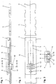
- Figure 1 shows a first faceplate 1 and a second faceplate 2, which are opposite each other at a distance, which distance may vary depending on the particular fitting installation situation.
- the faceplate 1 is - as can be seen in particular from Figure 2 - provided with an elongated hole 3, which is provided at least over most of its length with an inner edge fine toothing 4.
- the faceplate 2 has recesses 5 on the edge in the region of its cut-to-length free end.
- the two face plates 1 and 2 can be coupled to one another in a positive and non-positive manner by means of a connecting plate 6.
- This connecting plate 6 is provided on its underside, that is to say on its side facing the faceplate 1, with a fine toothed strip 9 which can engage in the elongated internal toothing 4, and it also has a distance from this fine toothed strip 9 and preferably in the region of the one to be coupled Face plate 2 facing end formed on the edge side coupling lugs 7, which can engage in the recesses 5 of the face plate 2.
- a pin 10 which is designed as a hollow pin, is formed on the connecting plate 6 at a short distance from the fine toothed strip 9, so that it enables a fastening screw to pass through.
- a peg-shaped support lug 8 is provided, which in the preassembly position shown in FIG. 1 rests on the faceplate 1 in the same way as the dome lugs 7 and ensures the spaced parallel position of the connecting plate 6 with respect to the faceplate 1 .
- the clamping and sliding connection between the connecting plate 6 and the faceplate 1 is ensured by an elastic element 11 which is applied to the pin 10 and is located between this pin 10 and the inner walls of the elongated hole 3.
- the dimensioning is such that the pin 10 is held tightly in the elongated hole 3, but at the same time is displaceable in the longitudinal direction of the arrow in the longitudinal direction X when using a corresponding actuating force in order to lead to a coupling of the two face plates 1 and 2.
- the elastic element 11 consists of a sleeve part, which preferably has a guide shoulder resting on the faceplate 1, which acts upon the action of a vertical force exerted in the direction of arrow Y, that is, when the coupling between the two faceplates 1 and 2 is made, can be suppressed.
- the elastic element 11 consists of a molded plastic part which, as shown in FIG. 3, has outer guides 14 which overlap the faceplate 1 in the region of the elongated hole edges. Furthermore, this molded part can have inner guides 12, into which an extension 15 of the pin 10 engages and thus positions the elastic element 11 with respect to the pin 10.
- the elongated hole 3 is slightly enlarged at the end associated with the pin 10, so that the pin 10 and the elastic element 11 attached to it can be inserted into the elongated hole when the connecting plate 6 with the faceplate 1 encloses a right angle, whereupon the connecting plate 6 together with the pin 10 and the elastic element 11 is rotated through 90 ° and can thus be pre-fixed in the slot 13.
- the faceplate 1 is supplied in the form shown in FIGS. 1 to 3 together with the pre-fixed connecting plate 6.
- the faceplate 1 can accordingly be fastened in the associated faceplate groove during fitting installation, with no special consideration being given to the connecting plate 6, since this practically constitutes an integral part of the faceplate 1.
- FIG. 4 shows the first step of this coupling process, in which the connecting plate 6 is displaced in the longitudinal direction of the faceplate in the direction of the arrow X parallel to the faceplate 1, 2 until the coupling attachments 7 with the associated recesses 5 are aligned on the faceplate 2.
- This displacement movement only counteracts the clamping caused by the elastic elements between the pin 10 and the elongated hole 3, but this clamping can be overcome without difficulty by exerting a corresponding longitudinal pushing force.
- Figure 5 shows the coupling process following the longitudinal displacement of the connecting plate 6, in which a vertical force is exerted on the connecting plate 6 in the direction of arrow Y, preferably in such a way that the coupling attachments 7 are first brought into engagement with the recesses 5, that is to say the connecting plate 6 is tilted.
- the fine toothed strip 9 and the fine toothing 4 on the inner edges of the elongated hole 3 of the faceplate 1.
- the pin 10 can follow the tilting movement practically unhindered due to the presence of the elastic element 11.
- Figure 6 shows the finished dome connection, in which the parallel position between the connecting plate 6 and faceplate 1, 2 is again established and a positive and positive connection is given.
- the support shoulder 8 is located in the long slot 3.
- a fastening screw can be introduced via the screw passage opening 13 shown in FIG.
Abstract
Description
Die Erfindung betrifft eine Vorrichtung zur form- und kraftschlüssigen Kupplung von Stulpschienen mittels einer die jeweils einander zugeordneten Stulpschienen übergreifenden und unterschiedliche gegenseitige Abstände überbrückenden Verbindungsplatte mit zur Stulpschiene gerichteter Feinzahnleiste, die mit der einen Stulpschiene über eine an Langloch-Innenwänden der Stulpschiene ausgebildete Feinverzahnung und mit der anderen Stulpschiene über an deren Längsrändern vorgesehene Ausnehmungen kuppelbar ist und gegebenenfalls eine Schraubendurchtrittsöffnung aufweist.The invention relates to a device for the positive and non-positive coupling of cuff rails by means of a connecting plate spanning the mutually assigned cuff rails and bridging different mutual distances, with a fine toothed strip directed towards the cuff rail, which with the one cuff rail via a fine toothing formed on elongated hole inner walls of the cuff rail and with the other faceplate can be coupled via recesses provided on its longitudinal edges and optionally has a screw passage opening.
Vorrichtungen dieser Art sind bekannt. Dabei stellt die Verbindungsplatte im Regelfall ein separates Teil dar, das bei der Beschlagmontage zur Verfügung stehen und nach erfolgter Kupplung mit den beiden Stulpschienenenden mit dem Flügel verschraubt werden muß. Ungünstig ist dabei, daß diese separate Verbindungsplatte zum einen leicht verloren gehen und zum anderen auch eine zügige Montage erschweren kann, da dieses vergleichsweise kleine Teil den Händen des jeweiligen Monteurs leicht entgleiten und zu Boden fallen kann.Devices of this type are known. The connecting plate is usually a separate part that is available during the fitting assembly and must be screwed to the sash with the two faceplate ends after coupling. It is unfavorable that this separate connecting plate can easily get lost on the one hand and on the other hand can also make rapid assembly more difficult, since this comparatively small part can easily slip off the hands of the respective fitter and fall to the ground.
Es ist auch bereits bekannt, die Verbindungsplatte über eine zum Beispiel ein großes Spiel aufweisende Vernietung bezüglich der Stulpschiene zu haltern und damit sicherzustellen, daß diese Verbindungsplatte nicht mehr verloren gehen kann. Nachteilig bei dieser Hilfslösung ist, daß die sehr lose gehalterte Verbindungsplatte leicht um die Nietverbindung schwenken und damit nach der Stulpschienenmontage auch eine Fehllage einnehmen kann, aus der sie nicht mehr in die Kuppellage verschwenkbar ist, so daß der Beschlag zumindest teilweise wieder demontiert werden muß, um die Verbindungsplatten-Fehllage korrigieren zu können.It is also already known to hold the connection plate by means of a rivet with respect to the faceplate, for example with a large clearance, and thus to ensure that this connection plate can no longer be lost. A disadvantage of this auxiliary solution is that the very loosely held connecting plate can pivot slightly around the rivet connection and can therefore also assume an incorrect position after the faceplate mounting, from which it can no longer be pivoted into the dome position, so that the fitting must at least partially be removed again. to correct the misalignment of the connecting plates.
Aufgabe der Erfindung ist es, eine Vorrichtung der eingangs angegebenen Art auf einfache Weise so auszugestalten, daß diese Verbindungsplatte einen nicht verlierbaren Bestandteil des Beschlages darstellt, eine werksseitig definierte Montageposition aufweist und eine einfache und schnell justierbare Kraft- und Formschlußverbindung zwischen den beiden Stulpschienenenden bei der Montage gewährleistet.The object of the invention is to design a device of the type mentioned in a simple manner so that this connecting plate is a non-captive part of the fitting, has a factory-defined mounting position and ensures a simple and quickly adjustable force and positive connection between the two faceplate ends during assembly.
Gelöst wird diese Aufgabe nach der Erfindung im wesentlichen dadurch, daß die mit der Feinzahnleiste und mit dazu in Längsrichtung beabstandeten Kuppelansätzen versehene Verbindungsplatte über eine Klemm-Schiebeverbindung an der das Langloch mit der Feinverzahnung aufweisenden Stulpschiene gehaltert und dabei zumindest über die sich auf der Stulpschiene abstützenden Kuppelansätze in einer Grundstellung gehalten ist, in der die Feinverzahnungen von Stulpschiene und Verbindungsplatte außer Eingriff und über die Klemm-Schiebeverbindung parallel zueinander verschiebbar sind.This object is achieved according to the invention essentially in that the connecting plate provided with the fine toothed strip and with longitudinally spaced dome lugs is held by means of a clamping and sliding connection on the faceplate having the elongated hole with the fine toothing, and at least via those which are supported on the faceplate Coupling approaches are held in a basic position in which the fine toothing of the faceplate and connecting plate are disengaged and can be moved parallel to one another via the clamping and sliding connection.
Durch die Schaffung einer justierbaren Klemm-Schiebeverbindung zwischen der das Langloch mit der Innenfeinverzahnung aufweisenden Stulpschiene und der Verbindungsplatte wird insbesondere in Verbindung mit der beidendigen Abstützung der Verbindungsplatte bezüglich der Stulpschiene erreicht, daß die Verbindungsplatte in ihrer Grundposition bezüglich der Stulpschiene eindeutig lagenfixiert ist und der Kupplungsvorgang zwischen den beiden Stulpschienen durch eine einfache Längsverschiebung der Verbindungsplatte mit anschließender Vertikalverrastung erfolgen kann. Fehlmontagen sind auf diese Weise ausgeschlossen und Montageunterbrechungen aufgrund fehlstehender oder verlorener Verbindungsplatten können nicht mehr auftreten.By creating an adjustable clamping and sliding connection between the faceplate having the elongated hole with the internal fine toothing and the connecting plate, in particular in conjunction with the two-sided support of the connecting plate with respect to the faceplate, the connecting plate is clearly fixed in position in relation to the faceplate and the coupling process can be done between the two face plates by a simple longitudinal displacement of the connecting plate with subsequent vertical locking. Incorrect assemblies are excluded in this way and assembly interruptions due to missing or lost connecting plates can no longer occur.
Die Klemm-Schiebeverbindung wird vorzugsweise dadurch realisiert, daß auf einem in den Stulpschienenlängsschlitz eingreifenden, an die Verbindungsplatte angeformten Zapfen ein hülsenförmiges Teil aus elastischem Material angebracht wird, das zum einen die erforderliche Klemmwirkung erbringt und zum anderen die notwendige Längsschiebebewegung zuläßt.The clamp-slide connection is preferably realized in that a sleeve-shaped part made of elastic material is attached to a pin which engages in the faceplate longitudinal slot and is formed on the connecting plate and which, on the one hand, provides the required clamping action and, on the other hand, permits the necessary longitudinal slide movement.
Besonders vorteilhafte Ausgestaltungen der Erfindung sind in den Unteransprüchen angegeben.Particularly advantageous embodiments of the invention are specified in the subclaims.
Die Erfindung wird nachfolgend anhand eines Ausführungsbeispiels unter Bezugnahme auf die Zeichnung näher erläutert; in der Zeichnung zeigt:
- Figur 1
- eine Teilschnittdarstellung zweier einander gegenüberliegender Stulpschienen vor einer Kupplung durch die Verbindungsplatte,
Figur 2- eine Draufsicht der Anordnung nach Figur 1,
Figur 3- eine schematische schnittdarstellung entsprechend der Linie A-A in Figur 1,
Figur 4- eine der Figur 1 entsprechende Darstellung entsprechend einer ersten Kupplungsphase,
Figur 5- die Anordnung nach
Figur 4 in einer zweiten Kupplungsphase, bei der die beiden Stulpschienen über die Ausnehmungen und Feinverzahnungen gekuppelt werden, und Figur 6- eine Darstellung der dritten Phase der Kupplung, bei der die form- und kraftschlüssige Kupplung der beiden Stulpschienen über die Verbindungsplatte erreicht ist.
- Figure 1
- 2 shows a partial sectional illustration of two face-to-face rails in front of a coupling through the connecting plate,
- Figure 2
- 2 shows a top view of the arrangement according to FIG. 1,
- Figure 3
- 2 shows a schematic sectional illustration along the line AA in FIG. 1,
- Figure 4
- 1 shows a representation corresponding to a first coupling phase,
- Figure 5
- the arrangement of Figure 4 in a second coupling phase, in which the two cuff rails are coupled via the recesses and fine teeth, and
- Figure 6
- a representation of the third phase of the coupling, in which the positive and non-positive coupling of the two faceplates is achieved via the connecting plate.
Figur 1 zeigt eine erste Stulpschiene 1 und eine zweite Stulpschiene 2, die einander mit Abstand gegenüberliegen, wobei dieser Abstand in Abhängigkeit von der jeweiligen Beschlagsmontagesituation unterschiedlich sein kann.Figure 1 shows a first faceplate 1 and a
Die Stulpschiene 1 ist - wie dies insbesondere der Figur 2 zu entnehmen ist - mit einem Langloch 3 versehen, das zumindest auf dem größten Teil seiner Länge mit einer Innenrand-Feinverzahnung 4 versehen ist.The faceplate 1 is - as can be seen in particular from Figure 2 - provided with an
Die Stulpschiene 2 weist im Bereich ihres ablängbaren freien Endes randseitige Ausnehmungen 5 auf. Die beiden Stulpschienen 1 und 2 können miteinander form- und kraftschlüssig mittels einer Verbindungsplatte 6 gekuppelt werden.The
Diese Verbindungsplatte 6 ist an ihrer Unterseite, das heißt ihrer der Stulpschiene 1 zugewandten Seite mit einer Feinzahnleiste 9 versehen, die in die Langloch-Innenverzahnung 4 eingreifen kann, und sie weist ferner mit Abstand von dieser Feinzahnleiste 9 und vorzugsweise im Bereich ihres der zu kuppelnden Stulpschiene 2 zugewandten Endes randseitig ausgebildete Kuppelansätze 7 auf, die in die Ausnehmungen 5 der Stulpschiene 2 eingreifen können.This connecting
An die Verbindungsplatte 6 ist mit einem geringen Abstand zur Feinzahnleiste 9 ein Zapfen 10 angeformt, der als Hohlzapfen ausgebildet ist, so daß er den Durchtritt einer Befestigungsschraube ermöglicht.A
Im Bereich des den Kuppelansätzen 7 gegenüberliegenden Endes der Verbindungsplatte 6 ist ein zapfenförmiger Stützansatz 8 vorgesehen, der in der in Figur 1 gezeigten Vormontageposition in gleicher Weise wie die Kuppelansätze 7 auf der Stulpschiene 1 aufliegt und die beabstandete Parallellage der Verbindungsplatte 6 bezüglich der Stulpschiene 1 gewährleistet.In the area of the end of the connecting
Die Klemm-Schiebeverbindung zwischen der Verbindungsplatte 6 und der Stulpschiene 1 wird durch ein elastisches Element 11 sichergestellt, das auf den Zapfen 10 aufgebracht und zwischen diesem Zapfen 10 und den Innenwänden des Langlochs 3 gelegen ist. Dabei ist die Dimensionierung so getroffen, daß der Zapfen 10 stramm im Langloch 3 gehaltert, gleichzeitig aber bei Aufwendung einer entsprechenden Betätigungskraft in Pfeilrichtung X in Langloch-Längsrichtung verschiebbar ist, um zu einer Kupplung der beiden Stulpschienen 1 und 2 hinzuführen.The clamping and sliding connection between the connecting
In einer einfachen Ausführungsvariante der Erfindung besteht das elastische Element 11 aus einem Hülsenteil, das bevorzugt einen auf der Stulpschiene 1 aufliegenden Führungsansatz aufweist, der bei Einwirkung einer in Pfeilrichtung Y ausgeübten Vertikalkraft, das heißt dann, wenn die Kupplung zwischen den beiden Stulpschienen 1 und 2 vorgenommen wird, überdrückbar ist.In a simple embodiment variant of the invention, the
Gemäß einer bevorzugten Ausführungsform der Erfindung besteht das elastische Element 11 aus einem Kunststoff-Formteil, das entsprechend der Darstellung in Figur 3 Außenführungen 14 aufweist, welche die Stulpschiene 1 im Bereich der Langlochränder übergreifen. Ferner kann dieses Formteil Innenführungen 12 besitzen, in die ein Ansatz 15 des Zapfens 10 eingreift und somit das elastische Element 11 bezüglich des Zapfens 10 positioniert.According to a preferred embodiment of the invention, the
Wie die Draufsicht an Figur 2 erkennen läßt, ist das Langloch 3 an dem dem Zapfen 10 zugeordneten Ende etwas erweitert, so daß der Zapfen 10 und das an ihm befestigte elastische Element 11 in das Langloch eingeführt werden können, wenn die Verbindungsplatte 6 mit der Stulpschiene 1 einen rechten Winkel einschließt, worauf dann die Verbindungsplatte 6 zusammen mit Zapfen 10 und elastischem Element 11 um 90° gedreht und auf diese Weise im Langloch 13 vorfixiert werden kann.As can be seen from the top view in FIG. 2, the
Die Stulpschiene 1 wird in der in den Figuren 1 bis 3 gezeigten Form zusammen mit der vorfixierten Verbindungsplatte 6 ausgeliefert. Die Stulpschiene 1 kann demgemäß in der zugehörigen Stulpschienenaufnahmenut bei der Beschlagsmontage befestigt werden, wobei keine besondere Rücksicht auf die Verbindungsplatte 6 genommen werden muß, da diese praktisch einen festen Bestandteil der Stulpschiene 1 darstellt.The faceplate 1 is supplied in the form shown in FIGS. 1 to 3 together with the
Die form- und kraftschlüssige Kupplung der beiden Stulpschienen 1 und 2 mittels der Verbindungsplatte 6 wird anhand der Figuren 4 bis 6 erläutert.The positive and non-positive coupling of the two
Figur 4 zeigt den ersten Schritt dieses Kupplungsvorgangs, bei dem die Verbindungsplatte 6 in Stulpschienenlängsrichtung in Pfeilrichtung X parallel zu den Stulpschienen 1, 2 verschoben wird, bis die Kuppelansätze 7 mit den zugehörigen Ausnehmungen 5 an der Stulpschiene 2 ausgerichtet sind. Dieser Verschiebebewegung wirkt lediglich die durch das elastische Elemente bewirkte Klemmung zwischen Zapfen 10 und Langloch 3 entgegen, aber diese Klemmung ist durch Ausübung einer entsprechenden Längsschiebekraft ohne Schwierigkeiten überwindbar.FIG. 4 shows the first step of this coupling process, in which the connecting
Figur 5 zeigt den auf die Längsverschiebung der Verbindungsplatte 6 folgenden Kuppelvorgang, bei dem auf die Verbindungsplatte 6 eine Vertikalkraft in Pfeilrichtung Y ausgeübt wird, und zwar vorzugsweise in der Art, daß zunächst die Kuppelansätze 7 in Eingriff mit den Ausnehmungen 5 gebracht werden, das heißt die Verbindungsplatte 6 gekippt wird. Dabei ergibt sich aber auch bereits ein Eingriff zwischen der Feinzahnleiste 9 und der Feinverzahnung 4 an den Innenrändern des Langlochs 3 der Stulpschiene 1. Der Zapfen 10 kann aufgrund des Vorhandenseins des elastischen Elements 11 der Kippbewegung praktisch unbehindert folgen.Figure 5 shows the coupling process following the longitudinal displacement of the connecting
Figur 6 zeigt die fertige Kuppelverbindung, bei der wieder die Parallellage zwischen Verbindungsplatte 6 und Stulpschienen 1, 2 hergestellt und ein Kraft- und Formschluß gegeben ist. Der Stützansatz 8 befindet sich im Langschlitz 3.Figure 6 shows the finished dome connection, in which the parallel position between the connecting
In der dargestellten Kuppelposition kann über die in Figur 2 zu sehende Schraubendurchtrittsöffnung 13 eine Befestigungsschraube eingebracht und damit die Endfixierung der Kuppelverbindung zwischen den Stulpschienen 1 und 2 und dem nicht dargestellten Flügelrahmen vorgenommen werden.In the coupling position shown, a fastening screw can be introduced via the
- 1 Stulpschiene1 faceplate
- 2 Stulpschiene2 faceplate
- 3 Längsschlitz3 longitudinal slots
- 4 Feinverzahnung4 fine toothing
- 5 Ausnehmungen5 recesses
- 6 Verbindungsplatte6 connecting plate
- 7 Kuppelansätze7 dome attachments
- 8 Stützansatz8 support approach
- 9 Feinzahnleiste9 fine tooth rack
- 10 Zapfen10 cones
- 11 Elastisches Element11 Elastic element
- 12 Innenführung12 inner guide
- 13 Schraubendurchtrittsöffnung13 screw passage opening
- 14 Außenführung14 External guidance
- 15 Ringbund15 ring collar
Claims (9)
- Apparatus for the shape-locked and force-transmitting coupling of face rails (1, 2) by means of a connection plate (6), which engages over the respective mutually associated face rails, and bridges different mutual spacings, the connection plate (6) having a fine-toothed strip (9) directed towards the face rail (1), which can be coupled to the one face rail (1) via a fine-toothed arrangement (4) formed at elongate slot inner walls of the face rail (1), and which can be coupled to the other face rail (2) via cut-outs (5) provided at its longitudinal edges, and which optionally has an aperture (13) for the passage of a screw,
characterised in that
the connection plate (6), which is provided with the fine-toothed strip (9) and with coupling projections (7) spaced therefrom in the longitudinal direction, is held via a clamping-sliding connection (3, 10, 11) at the face rail (1) having the elongate slot (3) with the fine-toothed arrangement (4), and is thereby held via the coupling projections (7), which are supported on the face rail (1) in a basic position, in which the fine-toothed arrangements (4, 9) of the face rail (1) and the connection plate (6) are out of engagement, and are displaceable parallel to one another via the clamping-sliding connection (3, 10, 11). - Apparatus in accordance with claim 1,
characterised in that
the connection plate (1) has a support projection (8) at the end opposite to the coupling projection (7), with the support projection (8) contacting the face plate (1) in the basic position, and determining, together with the coupling projections (7) the spaced apart parallel position of the connection plate (6) relative to the face rails (1). - Apparatus in accordance with claim 1 or claim 2,
characterised in that
the clamping-sliding connection (3, 10, 11) consists of a spigot (10) formed on the connection plate (6), which engages into the face-plate longitudinal slot (3), and preferably of a resilient element (11), which acts between the spigot (10) and the longitudinal slot walls. - Apparatus in accordance with claim 3,
characterised in that
the spigot (10) is formed as a hollow spigot with an associated through-opening (13) for a screw. - Apparatus in accordance with claim 3 or claim 4,
characterised in that
the resilient element (11) consists of a sleeve-like plastic part, which can be mounted on the spigot (10) or pushed over the spigot (10). - Apparatus in accordance with claim 3 or claim 4,
characterised in that
the resilient element (11) consists of a sleeve part, which is tightly displaceably guided in the face rail elongate slot (3) and has a central clamping opening for the spigot (10) provided on the connection plate (6). - Apparatus in accordance with claim 5,
characterised in that
the resilient sleeve-like element (11) has a guide projection, which contacts the face-plate (1) and which can be overcome by the action of a vertical force. - Apparatus in accordance with claim 1,
characterised in that
the resilient sleeve part (11) consists, for example, of plastic and has outer guides (14) for the longitudinal slot edges of the face rail (1). - Apparatus in accordance with claim 8,
characterised in that
the resilient sleeve part (11) has, in addition to the outer guides (14), an inner guide (12) into which a ring collar (15) of the spigot (10) of the connection plate (6) engages.
Applications Claiming Priority (2)
| Application Number | Priority Date | Filing Date | Title |
|---|---|---|---|
| DE9300178U | 1993-01-08 | ||
| DE9300178U DE9300178U1 (en) | 1993-01-08 | 1993-01-08 |
Publications (2)
| Publication Number | Publication Date |
|---|---|
| EP0605782A1 EP0605782A1 (en) | 1994-07-13 |
| EP0605782B1 true EP0605782B1 (en) | 1996-08-21 |
Family
ID=6887935
Family Applications (1)
| Application Number | Title | Priority Date | Filing Date |
|---|---|---|---|
| EP93118767A Expired - Lifetime EP0605782B1 (en) | 1993-01-08 | 1993-11-22 | Joint device for face plates |
Country Status (3)
| Country | Link |
|---|---|
| EP (1) | EP0605782B1 (en) |
| AT (1) | ATE141665T1 (en) |
| DE (2) | DE9300178U1 (en) |
Families Citing this family (13)
| Publication number | Priority date | Publication date | Assignee | Title |
|---|---|---|---|---|
| DE19513837C1 (en) * | 1995-04-12 | 1996-05-15 | Weidtmann Wilhelm Kg | Joint between window=linkage ends |
| FR2772822B1 (en) * | 1997-12-18 | 2000-02-04 | Ferco Int Usine Ferrures | HEAD LINK DEVICE |
| GB2336393A (en) * | 1998-03-24 | 1999-10-20 | Securistyle Ltd | Adjustable connectors for a shootbolt mechanism |
| DE19828268A1 (en) * | 1998-06-25 | 1999-12-30 | Winkhaus Fa August | Door and window transmission fitments using linear drive bars |
| DE19910828A1 (en) | 1999-03-11 | 2000-09-14 | Schaeffler Waelzlager Ohg | Tensioning device for traction devices |
| DE19942821B4 (en) * | 1999-09-08 | 2007-07-26 | Roto Frank Ag | Espagnolette system for windows, doors and the like |
| DE10013707A1 (en) * | 2000-03-21 | 2001-09-27 | Siegenia Frank Kg | Window or door fittings assembly and detail include two fittings toothing to engage when first fitting is tipped by spring relative third fitting for drive rod system. |
| GB0304406D0 (en) * | 2003-02-27 | 2003-04-02 | Trojan Hardware & Designs Ltd | Shoot bolt mechanism |
| DE202004004009U1 (en) * | 2004-03-15 | 2005-07-28 | Mayer & Co. | fitting assembly |
| DE102009054644B4 (en) * | 2009-12-15 | 2014-12-04 | Roto Frank Ag | Fitting assembly for a window, a door, a flap or the like |
| DE102014003754A1 (en) | 2014-03-18 | 2015-09-24 | Kfv Karl Fliether Gmbh & Co. Kg | Method for fitting fogging |
| CN106080325A (en) * | 2016-08-03 | 2016-11-09 | 南京创源天地动力科技有限公司 | The connection unit of seat back muscle in a kind of automobile |
| DE202021105443U1 (en) | 2021-10-07 | 2023-01-10 | Gretsch-Unitas GmbH Baubeschläge | Push rod connector and door or window assembly |
Family Cites Families (6)
| Publication number | Priority date | Publication date | Assignee | Title |
|---|---|---|---|---|
| DE2206795C3 (en) * | 1972-02-12 | 1982-04-08 | August Bilstein GmbH & Co KG, 5828 Ennepetal | Espagnolette fitting, in particular central lock provided with corner deflections for windows, doors or the like. |
| DE2504420A1 (en) * | 1975-02-03 | 1976-08-05 | Fuhr C Fa | Push rod window locking - has adjusting arrangement with serrated-edge slit meshing with leaf spring loaded knob |
| DE2506003A1 (en) * | 1975-02-13 | 1976-08-19 | Weidtmann Fa Wilhelm | Connector for window actuator cover strips - has toothed segment and pin for ensuring adjustment in connection |
| DE2741408C2 (en) * | 1977-09-14 | 1982-11-25 | Fa. Aug. Winkhaus, 4404 Telgte | Driving rail fitting |
| DE2836683A1 (en) * | 1978-08-22 | 1980-03-06 | Hautau Baubeschlag | Remote operated window closing mechanism - includes corner joint with cover strips connected by toothed bridging piece giving adjustment |
| DE8632641U1 (en) * | 1986-12-05 | 1987-02-19 | Mayer & Co., Salzburg, At |
-
1993
- 1993-01-08 DE DE9300178U patent/DE9300178U1/de not_active Expired - Lifetime
- 1993-11-22 AT AT93118767T patent/ATE141665T1/en not_active IP Right Cessation
- 1993-11-22 DE DE59303499T patent/DE59303499D1/en not_active Expired - Lifetime
- 1993-11-22 EP EP93118767A patent/EP0605782B1/en not_active Expired - Lifetime
Also Published As
| Publication number | Publication date |
|---|---|
| DE59303499D1 (en) | 1996-09-26 |
| DE9300178U1 (en) | 1993-03-11 |
| ATE141665T1 (en) | 1996-09-15 |
| EP0605782A1 (en) | 1994-07-13 |
Similar Documents
| Publication | Publication Date | Title |
|---|---|---|
| EP0113809B1 (en) | Electrical plug-in connector with a locking device for an electrical contact element extending into a housing | |
| EP0605782B1 (en) | Joint device for face plates | |
| EP0694669A1 (en) | Device for connecting a window glass with a window regulator | |
| DE3744906C2 (en) | Furniture door hinge | |
| DE4409206C1 (en) | Base for an electrical protective-earth conductor terminal, as well as such a protective-earth conductor terminal | |
| EP0875084B1 (en) | Device for electrically connecting the frame or cabinet housing of a switching cabinet with the door | |
| EP0329843A1 (en) | Casing for an electrical apparatus | |
| DE4032865C2 (en) | Screw connection | |
| DE3838957A1 (en) | INSULATING CONNECTING DEVICE FOR BUILDING BOARDS | |
| DE3640012C2 (en) | ||
| EP1522826B1 (en) | Securing device for transporting and mounting a measuring assembly | |
| CH652269A5 (en) | Quick mounting base made of plastic, for fixing an electrical device or printed-circuit board | |
| DE2615242C2 (en) | Mounting base | |
| EP0139980B1 (en) | Collier de câble | |
| EP0480240B1 (en) | Sliding device to make a disconnection | |
| DE10393723B4 (en) | Plug connection and assembly method for producing at least one connection through an opening in a partition wall | |
| DE19711770C2 (en) | Mechanical overlap connection | |
| CH687716A5 (en) | Fitting. | |
| DE1912974C3 (en) | Door handle pin connection with locking teeth | |
| EP0681109B1 (en) | Joint for releasable fitting of two furniture parts | |
| EP1371530B1 (en) | Fastening assembly | |
| EP1077509A1 (en) | Rail mounted terminal bloc | |
| EP0205026B1 (en) | Hinge arm for a furniture hinge with a mounting plate | |
| DE2553509C2 (en) | Device for connecting a cover profile to a frame profile | |
| EP0491674A1 (en) | Snap-lock device |
Legal Events
| Date | Code | Title | Description |
|---|---|---|---|
| PUAI | Public reference made under article 153(3) epc to a published international application that has entered the european phase |
Free format text: ORIGINAL CODE: 0009012 |
|
| AK | Designated contracting states |
Kind code of ref document: A1 Designated state(s): AT DE FR IT |
|
| 17P | Request for examination filed |
Effective date: 19940824 |
|
| 17Q | First examination report despatched |
Effective date: 19951128 |
|
| GRAH | Despatch of communication of intention to grant a patent |
Free format text: ORIGINAL CODE: EPIDOS IGRA |
|
| GRAH | Despatch of communication of intention to grant a patent |
Free format text: ORIGINAL CODE: EPIDOS IGRA |
|
| GRAA | (expected) grant |
Free format text: ORIGINAL CODE: 0009210 |
|
| ITF | It: translation for a ep patent filed |
Owner name: BARZANO' E ZANARDO MILANO S.P.A. |
|
| AK | Designated contracting states |
Kind code of ref document: B1 Designated state(s): AT DE FR IT |
|
| PG25 | Lapsed in a contracting state [announced via postgrant information from national office to epo] |
Ref country code: FR Effective date: 19960821 |
|
| REF | Corresponds to: |
Ref document number: 141665 Country of ref document: AT Date of ref document: 19960915 Kind code of ref document: T |
|
| REF | Corresponds to: |
Ref document number: 59303499 Country of ref document: DE Date of ref document: 19960926 |
|
| EN | Fr: translation not filed | ||
| PLBE | No opposition filed within time limit |
Free format text: ORIGINAL CODE: 0009261 |
|
| STAA | Information on the status of an ep patent application or granted ep patent |
Free format text: STATUS: NO OPPOSITION FILED WITHIN TIME LIMIT |
|
| 26N | No opposition filed | ||
| PGFP | Annual fee paid to national office [announced via postgrant information from national office to epo] |
Ref country code: AT Payment date: 20091113 Year of fee payment: 17 |
|
| PGFP | Annual fee paid to national office [announced via postgrant information from national office to epo] |
Ref country code: IT Payment date: 20091121 Year of fee payment: 17 |
|
| PGFP | Annual fee paid to national office [announced via postgrant information from national office to epo] |
Ref country code: DE Payment date: 20100129 Year of fee payment: 17 |
|
| PG25 | Lapsed in a contracting state [announced via postgrant information from national office to epo] |
Ref country code: AT Free format text: LAPSE BECAUSE OF NON-PAYMENT OF DUE FEES Effective date: 20101122 |
|
| REG | Reference to a national code |
Ref country code: DE Ref legal event code: R119 Ref document number: 59303499 Country of ref document: DE Effective date: 20110601 Ref country code: DE Ref legal event code: R119 Ref document number: 59303499 Country of ref document: DE Effective date: 20110531 |
|
| PG25 | Lapsed in a contracting state [announced via postgrant information from national office to epo] |
Ref country code: DE Free format text: LAPSE BECAUSE OF NON-PAYMENT OF DUE FEES Effective date: 20110531 |
|
| PG25 | Lapsed in a contracting state [announced via postgrant information from national office to epo] |
Ref country code: IT Free format text: LAPSE BECAUSE OF NON-PAYMENT OF DUE FEES Effective date: 20101122 |