EP0604991A2 - Öffnungs-/Schliessmechanismus für eine Tonerausgabeöffnung, welche dem Toner erlaubt herauszufallen - Google Patents
Öffnungs-/Schliessmechanismus für eine Tonerausgabeöffnung, welche dem Toner erlaubt herauszufallen Download PDFInfo
- Publication number
- EP0604991A2 EP0604991A2 EP93121036A EP93121036A EP0604991A2 EP 0604991 A2 EP0604991 A2 EP 0604991A2 EP 93121036 A EP93121036 A EP 93121036A EP 93121036 A EP93121036 A EP 93121036A EP 0604991 A2 EP0604991 A2 EP 0604991A2
- Authority
- EP
- European Patent Office
- Prior art keywords
- toner
- main body
- shutter member
- toner cartridge
- closing
- Prior art date
- Legal status (The legal status is an assumption and is not a legal conclusion. Google has not performed a legal analysis and makes no representation as to the accuracy of the status listed.)
- Granted
Links
Images


Classifications
-
- G—PHYSICS
- G03—PHOTOGRAPHY; CINEMATOGRAPHY; ANALOGOUS TECHNIQUES USING WAVES OTHER THAN OPTICAL WAVES; ELECTROGRAPHY; HOLOGRAPHY
- G03G—ELECTROGRAPHY; ELECTROPHOTOGRAPHY; MAGNETOGRAPHY
- G03G15/00—Apparatus for electrographic processes using a charge pattern
- G03G15/06—Apparatus for electrographic processes using a charge pattern for developing
- G03G15/08—Apparatus for electrographic processes using a charge pattern for developing using a solid developer, e.g. powder developer
- G03G15/0822—Arrangements for preparing, mixing, supplying or dispensing developer
- G03G15/0877—Arrangements for metering and dispensing developer from a developer cartridge into the development unit
- G03G15/0881—Sealing of developer cartridges
- G03G15/0886—Sealing of developer cartridges by mechanical means, e.g. shutter, plug
-
- G—PHYSICS
- G03—PHOTOGRAPHY; CINEMATOGRAPHY; ANALOGOUS TECHNIQUES USING WAVES OTHER THAN OPTICAL WAVES; ELECTROGRAPHY; HOLOGRAPHY
- G03G—ELECTROGRAPHY; ELECTROPHOTOGRAPHY; MAGNETOGRAPHY
- G03G15/00—Apparatus for electrographic processes using a charge pattern
- G03G15/06—Apparatus for electrographic processes using a charge pattern for developing
- G03G15/08—Apparatus for electrographic processes using a charge pattern for developing using a solid developer, e.g. powder developer
- G03G15/0822—Arrangements for preparing, mixing, supplying or dispensing developer
- G03G15/0848—Arrangements for testing or measuring developer properties or quality, e.g. charge, size, flowability
- G03G15/0849—Detection or control means for the developer concentration
- G03G15/0855—Detection or control means for the developer concentration the concentration being measured by optical means
-
- G—PHYSICS
- G03—PHOTOGRAPHY; CINEMATOGRAPHY; ANALOGOUS TECHNIQUES USING WAVES OTHER THAN OPTICAL WAVES; ELECTROGRAPHY; HOLOGRAPHY
- G03G—ELECTROGRAPHY; ELECTROPHOTOGRAPHY; MAGNETOGRAPHY
- G03G15/00—Apparatus for electrographic processes using a charge pattern
- G03G15/06—Apparatus for electrographic processes using a charge pattern for developing
- G03G15/08—Apparatus for electrographic processes using a charge pattern for developing using a solid developer, e.g. powder developer
- G03G15/0822—Arrangements for preparing, mixing, supplying or dispensing developer
- G03G15/0865—Arrangements for supplying new developer
- G03G15/0867—Arrangements for supplying new developer cylindrical developer cartridges, e.g. toner bottles for the developer replenishing opening
- G03G15/0868—Toner cartridges fulfilling a continuous function within the electrographic apparatus during the use of the supplied developer material, e.g. toner discharge on demand, storing residual toner, acting as an active closure for the developer replenishing opening
-
- G—PHYSICS
- G03—PHOTOGRAPHY; CINEMATOGRAPHY; ANALOGOUS TECHNIQUES USING WAVES OTHER THAN OPTICAL WAVES; ELECTROGRAPHY; HOLOGRAPHY
- G03G—ELECTROGRAPHY; ELECTROPHOTOGRAPHY; MAGNETOGRAPHY
- G03G15/00—Apparatus for electrographic processes using a charge pattern
- G03G15/06—Apparatus for electrographic processes using a charge pattern for developing
- G03G15/08—Apparatus for electrographic processes using a charge pattern for developing using a solid developer, e.g. powder developer
- G03G15/0822—Arrangements for preparing, mixing, supplying or dispensing developer
- G03G15/0865—Arrangements for supplying new developer
- G03G15/0875—Arrangements for supplying new developer cartridges having a box like shape
-
- G—PHYSICS
- G03—PHOTOGRAPHY; CINEMATOGRAPHY; ANALOGOUS TECHNIQUES USING WAVES OTHER THAN OPTICAL WAVES; ELECTROGRAPHY; HOLOGRAPHY
- G03G—ELECTROGRAPHY; ELECTROPHOTOGRAPHY; MAGNETOGRAPHY
- G03G15/00—Apparatus for electrographic processes using a charge pattern
- G03G15/06—Apparatus for electrographic processes using a charge pattern for developing
- G03G15/08—Apparatus for electrographic processes using a charge pattern for developing using a solid developer, e.g. powder developer
- G03G15/0822—Arrangements for preparing, mixing, supplying or dispensing developer
- G03G15/0877—Arrangements for metering and dispensing developer from a developer cartridge into the development unit
- G03G15/0881—Sealing of developer cartridges
- G03G15/0882—Sealing of developer cartridges by a peelable sealing film
-
- G—PHYSICS
- G03—PHOTOGRAPHY; CINEMATOGRAPHY; ANALOGOUS TECHNIQUES USING WAVES OTHER THAN OPTICAL WAVES; ELECTROGRAPHY; HOLOGRAPHY
- G03G—ELECTROGRAPHY; ELECTROPHOTOGRAPHY; MAGNETOGRAPHY
- G03G15/00—Apparatus for electrographic processes using a charge pattern
- G03G15/06—Apparatus for electrographic processes using a charge pattern for developing
- G03G15/08—Apparatus for electrographic processes using a charge pattern for developing using a solid developer, e.g. powder developer
- G03G15/0822—Arrangements for preparing, mixing, supplying or dispensing developer
- G03G15/0877—Arrangements for metering and dispensing developer from a developer cartridge into the development unit
- G03G15/0881—Sealing of developer cartridges
- G03G15/0884—Sealing of developer cartridges by a sealing film to be ruptured or cut
-
- G—PHYSICS
- G03—PHOTOGRAPHY; CINEMATOGRAPHY; ANALOGOUS TECHNIQUES USING WAVES OTHER THAN OPTICAL WAVES; ELECTROGRAPHY; HOLOGRAPHY
- G03G—ELECTROGRAPHY; ELECTROPHOTOGRAPHY; MAGNETOGRAPHY
- G03G2215/00—Apparatus for electrophotographic processes
- G03G2215/06—Developing structures, details
- G03G2215/066—Toner cartridge or other attachable and detachable container for supplying developer material to replace the used material
- G03G2215/068—Toner cartridge or other attachable and detachable container for supplying developer material to replace the used material having a box like shape
-
- G—PHYSICS
- G03—PHOTOGRAPHY; CINEMATOGRAPHY; ANALOGOUS TECHNIQUES USING WAVES OTHER THAN OPTICAL WAVES; ELECTROGRAPHY; HOLOGRAPHY
- G03G—ELECTROGRAPHY; ELECTROPHOTOGRAPHY; MAGNETOGRAPHY
- G03G2215/00—Apparatus for electrophotographic processes
- G03G2215/06—Developing structures, details
- G03G2215/066—Toner cartridge or other attachable and detachable container for supplying developer material to replace the used material
- G03G2215/0685—Toner cartridge or other attachable and detachable container for supplying developer material to replace the used material fulfilling a continuous function within the electrographic apparatus during the use of the supplied developer material, e.g. toner discharge on demand, storing residual toner, not acting as a passive closure for the developer replenishing opening
-
- G—PHYSICS
- G03—PHOTOGRAPHY; CINEMATOGRAPHY; ANALOGOUS TECHNIQUES USING WAVES OTHER THAN OPTICAL WAVES; ELECTROGRAPHY; HOLOGRAPHY
- G03G—ELECTROGRAPHY; ELECTROPHOTOGRAPHY; MAGNETOGRAPHY
- G03G2215/00—Apparatus for electrophotographic processes
- G03G2215/06—Developing structures, details
- G03G2215/066—Toner cartridge or other attachable and detachable container for supplying developer material to replace the used material
- G03G2215/0687—Toner cartridge or other attachable and detachable container for supplying developer material to replace the used material using a peelable sealing film
-
- G—PHYSICS
- G03—PHOTOGRAPHY; CINEMATOGRAPHY; ANALOGOUS TECHNIQUES USING WAVES OTHER THAN OPTICAL WAVES; ELECTROGRAPHY; HOLOGRAPHY
- G03G—ELECTROGRAPHY; ELECTROPHOTOGRAPHY; MAGNETOGRAPHY
- G03G2215/00—Apparatus for electrophotographic processes
- G03G2215/06—Developing structures, details
- G03G2215/066—Toner cartridge or other attachable and detachable container for supplying developer material to replace the used material
- G03G2215/0692—Toner cartridge or other attachable and detachable container for supplying developer material to replace the used material using a slidable sealing member, e.g. shutter
-
- Y—GENERAL TAGGING OF NEW TECHNOLOGICAL DEVELOPMENTS; GENERAL TAGGING OF CROSS-SECTIONAL TECHNOLOGIES SPANNING OVER SEVERAL SECTIONS OF THE IPC; TECHNICAL SUBJECTS COVERED BY FORMER USPC CROSS-REFERENCE ART COLLECTIONS [XRACs] AND DIGESTS
- Y10—TECHNICAL SUBJECTS COVERED BY FORMER USPC
- Y10S—TECHNICAL SUBJECTS COVERED BY FORMER USPC CROSS-REFERENCE ART COLLECTIONS [XRACs] AND DIGESTS
- Y10S222/00—Dispensing
- Y10S222/01—Xerography
Definitions
- the present invention relates to a mechanism for opening/closing a toner falling aperture through which toner is supplied from a toner cartridge to the developing device in an image forming apparatus such as an electrostatic copying apparatus, a facsimile, a laser beam printer or the like.
- a toner cartridge is removably attached to a housing concave in the main body of the image forming apparatus.
- a toner cartridge of which toner has been used up, is to be replaced with a new toner cartridge.
- a toner cartridge has a sealing member made of an elastic sheet which removably covers, at the outer surface of the main body of the toner cartridge, a toner falling aperture formed in the bottom of the toner cartridge main body in which toner is housed.
- the sealing member is torn off, causing the toner falling aperture to be opened.
- toner falling through the toner falling aperture is supplied to the developing device which is disposed under the toner falling aperture.
- the sealing member thus torn off, is separated from the toner cartridge and taken out to the outside of the main body of the image forming apparatus.
- an image forming apparatus having an opening/closing mechanism for opening/closing a toner falling aperture formed in the bottom of the main body of a toner cartridge.
- the developing device may be made in the form of a unit and adapted to be inserted in and removed from a housing concave of the main body of an image forming apparatus.
- an image forming apparatus having an opening/closing mechanism for opening/closing a toner falling aperture formed in the top surface of the developing unit.
- the opening/closing mechanism of the developing unit is operated irrespectively of the operation of the opening/closing mechanism of the toner cartridge.
- the present invention is proposed with the object of providing an economical mechanism for opening/closing a toner falling aperture, which prevents toner from scattering.
- the present invention provides, as a first aspect, a mechanism for opening/closing a toner falling aperture formed in the bottom of the main body of a toner cartridge in which toner is housed, comprising: an elastic sealing member which is disposed inside of the toner cartridge main body and which is removably attached to the top surface of the bottom for closing the toner falling aperture; and taking-off means which is disposed inside of the toner cartridge main body, to which an end of the sealing member is secured, and which is adapted to take off the sealing member while winding the same thereon when the taking-off means is driven by an external driving source.
- the toner cartridge which has not been used yet is mounted on the main body of an image forming apparatus, and the taking-off means is then driven by the external drive source, so that the sealing member is wound on the taking-off means, causing the sealing member to be stripped off from the bottom of the toner cartridge main body. This causes the toner falling aperture to be opened.
- the sealing member to which toner is sticked is taken up by the taking-off means and held inside of the toner cartridge main body. This prevents toner from scattering outside of the toner cartridge when the toner cartridge is replaced.
- the taking-off means may comprise rotary toner delivery means for delivering toner housed inside of the toner cartridge main body, toward the toner falling aperture.
- the rotary toner delivery means may comprise a screw conveyor.
- the sealing member is a tape-like member.
- the sealing member is wound on a part of the rotary toner delivery means, no adverse effect is substantially exerted to the performance of the toner delivery means.
- the present invention provides, as another aspect, a mechanism for opening/closing a toner falling aperture, applied to an image forming apparatus having: a developing unit main body removably set to a housing concave in the main body of the image forming apparatus; a toner cartridge main body slidably connected to the top surface of the developing unit main body and removably set to the housing concave; and upper and lower toner falling apertures respectively formed in the bottom of the toner cartridge main body and in the top surface of the developing unit main body, the apertures being adapted to communicate with each other: the mechanism for opening/closing a toner falling aperture comprising: an upper shutter member slidably disposed under the bottom of the toner cartridge main body for opening/closing the upper toner falling aperture; first biasing means for biasing the upper shutter member to close the upper toner falling aperture; a lower shutter member slidably disposed on the top surface of the developing unit main body for opening/closing the lower toner falling aperture; second biasing means for biasing
- the second engaging means are engaged with each other, causing the upper shutter member to open the upper toner falling aperture.
- the second engaging means are disengaged from each other so that the first biasing means causes the upper shutter member to automatically close the upper toner falling aperture. This prevents toner from scattering.
- the engagement of the first engaging means causes the lower shutter member to open the lower toner falling aperture and the engagement of the second engaging means with each other causes the upper shutter member to open the upper toner falling aperture in association with the opening of the lower toner falling aperture.
- the disengagement of the first engaging means causes the first and second biasing means to automatically close the upper and lower toner falling apertures.
- the toner cartridge main body and the developing unit main body are relatively slidable with respect to each other by a pair of slide mechanisms including grooves and projecting members which are adapted to be engaged with each other, and the second engaging means are disposed between the bottom of the toner cartridge main body and the top surface of the developing unit main body and between the pair of slide mechanisms. If the second engaging means cross the grooves, it is difficult to seal the groove portions that the second engaging means cross. According to the present invention, however, the second engaging means do not cross the grooves and the like. It is therefore easy to seal the space between the bottom of the toner cartridge main body and the top surface of the developing unit main body.
- the mechanism for opening/closing a toner falling aperture further comprises: a first stopper disposed at a predetermined part of the housing concave for stopping, at a predetermined insertion stroke position, the toner cartridge main body which is inserted; and a second stopper disposed at a predetermined part of the housing concave for stopping, at a predetermined insertion stroke position, the developing unit main body which is inserted: and the positions where the developing unit main body and the toner cartridge main body are stopped by the respective stoppers, are different from each other such that the lower shutter member opens the lower toner falling aperture before the upper shutter member opens the upper toner falling aperture and that the upper shutter member closes the upper toner falling aperture before the lower shutter member closes the lower toner falling aperture when the developing unit main body and the toner cartridge main body connected thereto are integrally inserted in and removed from the housing concave.
- the lower shutter member opens the lower toner falling aperture before the upper shutter member opens the upper toner falling aperture, and the upper shutter member closes the upper toner falling aperture before the lower shutter member closes the lower toner falling aperture. This securely prevents toner from scattering between the opposite surfaces of the toner cartridge main body and the developing unit main body.
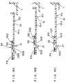
- Figs. 1 to 4 show a first embodiment of the present invention.
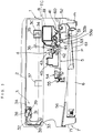
- a copying apparatus has, inside of the main body 1 thereof, (i) an optical system 3 where a document placed on a document placing plate 2 is illuminated and scanned, and light reflected from the document is guided to a photoreceptor drum 42, (ii) an image forming unit 4 where an electrostatic latent image formed on the photoreceptor drum 42 is converted into a toner image by a developing device 41, and the toner image is then transferred onto paper, and (iii) a paper delivery unit 5 where paper is pulled out from a paper feeding tray 61 in a paper housing portion 6 by a paper feeding roller 51 having a semicircular section, and the paper is passed through the image forming unit 4 and then discharged to a discharge tray 56 inside of the main body of the copying apparatus.
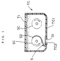
- a toner cartridge TC for supplying toner to the developing device 41.
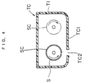
- a mechanism for opening/closing a toner falling aperture is characterized in that a sealing member S which closes a toner falling aperture TC2 in the toner cartridge TC, is adapted to be taken up by a screw conveyor SC, serving as rotary delivery means, disposed inside of the toner cartridge TC, as shown in Fig. 4.
- the copying apparatus main body 1 has a lower unit 7 partitioned by a lower casing 71, and an upper unit 8 partitioned by an upper casing 81 supported in a manner rotatable around a predetermined axis of rotation m at the lower end thereof, the upper unit 8 being relatively rotatable with respect to the lower unit 7.
- the copying apparatus main body 1 is of a so-called clamshell type in which the upper unit 8 is rotatably opened/closed with respect to the lower unit 7.
- the optical system 3 is arranged such that a document is illuminated by a fluorescent lamp 39 having a reflector plate 38 secured to a first moving frame 3A, and light reflected from the document is guided to the photoreceptor drum 42 after successively passing through a first mirror 31 secured to the first moving frame 3A, second and third mirrors 32, 33 secured to a second moving frame 3B, a lens 37, fourth and fifth mirrors 34, 35 secured to a third moving frame 3C, and a sixth mirror 36.
- the image forming unit 4 there are successively disposed, around the photoreceptor drum 42, a corona discharger 43, the developing device 41, a transferring corona discharger 44 and a cleaning device 45 in this order.
- the image forming unit 4 is arranged such that a document image is formed to form an electrostatic latent image on the outer peripheral surface of the photoreceptor drum 42 uniformly electrically charged by the corona discharger 43, the electrostatic latent image is converted into a toner image by the developing device 41, the toner image is transferred to paper by the transferring corona discharger 44, and residual toner is collected by the cleaning device 45.
- the paper delivery unit 5 comprises: the paper feeding roller 51 adapted to pull out paper, one by one, from the paper feeding tray 61; a delivery roller 52 for delivering paper from a manual paper feeding part 60 or the paper feeding tray 61; resist means 53 with which the tip of paper delivered by the delivery roller 52 comes in contact, causing the paper to temporarily wait, the resist means 53 being formed by driving roller means 53a and driven roller means 53b; a fixing unit 54 for fixing a toner image transferred onto paper; and a pair of discharging roller means 55.
- the toner cartridge TC comprises: a container-like toner cartridge main body T1; an aperture TC2 which is formed in the bottom TC1 of the toner cartridge main body T1 and through which toner is adapted to fall toward the developing device 41; a pair of screw conveyors SC disposed inside of the toner cartridge main body T1 in the longitudinal direction thereof; and the tape-like narrow sealing member S having one end S1 which closes the aperture TC2 at the inside of the toner cartridge main body T1 while the toner cartridge TC is not under use.
- the other end S2 of the sealing member S is secured to a spiral blade SC1 of one screw conveyor SC.
- the sealing member S is sticked to the edge of the aperture TC2 by heat fusion or the like.
- the screw conveyors SC are adapted to be rotated in opposite directions (See arrows shown by chain lines in Fig. 1) to feed toner in opposite direcitons (See white arrows in Fig. 2). This causes toner to be circulated while passing on the aperture TC2 inside of the toner cartridge main body T1.
- the toner cartridge main body T1 is provided at the pulling-side end thereof with a channel-like movable grip T2.
- the grip T2 can be housed in a concave portion T3 formed at the pulling-side end such that the grip T2 does not project from the pulling-side end when the grip T2 is not under use.
- the sealing member S is taken up by one of the screw conveyors SC under rotation. This causes the sealing member S to be torn off from the aperture TC2, thus opening the aperture TC2 (See Fig. 4).
- the sealing member S to which toner is sticked is taken up inside of the toner cartridge main body T1. This prevents toner from scattering outside of the toner cartridge TC when the toner cartridge TC is replaced. Accordingly, no toner scatters inside and outside of the copying apparatus main body 1 when the toner cartridge TC is replaced.
- the sealing member S is in the form of a narrow tape. Accordingly, even though the sealing member S is wound on a portion of the screw conveyor SC, no adverse effect is substantially exerted on the delivery performance of the screw conveyor SC.
- a toner stirring and delivery mechanism DM as shown in Fig. 5.
- a plurality of rotary plate-like stirring blades DM1 and the like are disposed in the toner delivery direction so that toner is stirred and delivered.
- a sealing member S can be taken up by one of the stirring blades DM1, and similar effects to those produced in the embodiment in Fig. 1, can be produced.
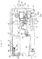
- a developing device 41 is arranged in the form of an integral developing unit GU, and toner is to be supplied by a replaceable toner cartridge TC.
- Other component elements in Fig. 7 are similar to those shown in Fig. 3. Thus, like parts in Fig. 7 are designated by like reference numerals used in Fig. 3, and the description thereof is here omitted.
- a copying apparatus is arranged such that the developing unit GU and the toner cartridge TC are integrally or individually inserted in and removed from a predetermined part of the copying apparatus main body 1 (the inserting direction is shown by K1, while the removing direction is shown by K2).
- an upper shutter member US and a lower shutter member SS are disposed for opening/closing a toner falling aperture TC2 of the toner cartridge TC and a toner falling aperture GU2 of the developing unit GU, respectively, and are adapted to be interlockingly operated.
- the developing unit GU and the toner cartridge TC are stopped when the insertion-side ends thereof come in contact with a stopper L (See Fig. 6C) at a predetermined insertion stroke position.
- the developing unit main body G1 has guide grooves GU3 in which both lateral edges of the lower shutter member SS are inserted. This enables the lower shutter member SS to be slided on the top surface GU1 of the developing unit main body G1. Further, the developing unit main body G1 has guide grooves GU4 in which projections TC3 of the toner cartridge TC are inserted. This enables the toner cartridge TC to be slidably inserted in and removed from the developing unit GU.
- the lower shutter member SS is made of a plate member and has a lower communicating aperture SS1 which is adapted to communicate with the aperture GU2 in the developing unit GU when the lower shutter member SS is slided to a predetermined position.
- the lower shutter member SS is provided on the top surface thereof with an upward projection SS2 engageable with a groove US2 in the upper shutter member US.
- the lower shutter member SS is provided at the underside thereof with a downward projection SS3, serving as first engaging means, which passes through a slit GU5 in the top surface GU1 of the developing unit GU and which is engageable with a projection J1 of the copying apparatus main body 1.
- the lower shutter member SS is normally biased toward the inserting direction K1 such that the aperture SS1 is positionally shifted toward the inserting direction K1 with respect to the aperture GU2 in the developing unit GU. That is, the lower shutter member SS is biased to close the aperture GU2.
- the lower shutter member SS When the downward projection SS3 of the lower shutter member SS is engaged with the projection J1 of the copying apparatus main body 1, the lower shutter member SS opens/closes the aperture GU2 in association with the insertion and removal of the developing unit GU.
- the groove US2 in the upper shutter member US and the upward projection SS2 of the lower shutter member SS form second engaging means for interlockingly operating the upper and lower shutter members US, SS.
- the toner cartridge main body T1 is a box-like container. Slidably attached to the toner cartridge main body T1 is the upper shutter member US for opening/closing the toner falling aperture TC2 formed in the bottom TC1 of the toner cartridge main body T1.
- the upper shutter member US has an upper communicating aperture US1 which is adapted to communicate with the aperture TC2 in the toner cartridge TC when the upper shutter member US is slided to a predetermined position.
- the upper shutter member US has the groove US2 engageble with the upward projection SS2 of the lower shutter member SS when the upper shutter member US is slided to a predetermined position.
- the upper shutter member US is normally biased toward the inserting direction K1 such that the aperture US1 is positionally shifted toward the inserting direction K1 with respect to the aperture TC2 in the toner cartridge TC. That is, the upper shutter member US is biased to close the aperture TC2.
- the compression coiled spring FS is contracted and the developing unit GU is relatively moved with respect to the lower shutter member SS, so that the aperture GU2 in the developing unit GU is opened.
- the developing unit GU is stopped as coming in contact with the stopper L (Fig. 15C).
- the operations above-mentioned may be reversed. That is, the developing unit GU may be removed with the aperture GU2 closed by the lower shutter member SS.
- the developing unit GU and the toner cartridge TC connected thereto are integrally inserted.
- the groove US2 in the upper shutter member US is engaged with the upward projection SS2 of the lower shutter member SS, and the apertures US1, SS1 in the both upper and lower shutter members US, SS communicate with each other.
- the developing unit GU and the toner cartridge TC are stopped as coming in contact with the stopper L (Fig. 6C).
- the operations above-mentioned may be reversed. That is, the developing unit GU and the toner cartridge TC may be removed with the apertures TC2, GU2 closed by the shutter members US, SS.
- the upper and lower shutter members US, SS for the toner cartridge TC and the developing unit GU are so biased as to close the apertures TC2, GU2. Accordingly, even though the toner cartridge TC alone or the developing unit GU alone is removed, no toner falls through the aperture TC2 or GU2.
- the upward projection SS2 and the groove US2 serving as engaging means for interlockingly operating the shutter members US, SS, are disposed between the bottom TC1 of the toner cartridge main body T1 and the top surface GU1 of the developing unit main body G1 and between the pair of guide grooves GU4. It is now supposed that the upward projection SS2 crosses the guide grooves GU4. In such a case, it is required to provide a space in which the upward projection SS2 is relatively moved with respect to the guide grooves GU4. It is difficult to seal such a space. According to the third embodiment, however, it is easy to seal the space between the bottom TC1 of the toner cartridge main body T1 and the top surface GU1 of the developing unit main body G1.
- Figs. 16A, 16B, 16C show a fourth embodiment of the present invention.
- the fourth embodiment differs from the third embodiment in Figs. 6A, 6B, 6C in the following two points.
Landscapes
- Physics & Mathematics (AREA)
- General Physics & Mathematics (AREA)
- Dry Development In Electrophotography (AREA)
- Electrophotography Configuration And Component (AREA)
Priority Applications (2)
| Application Number | Priority Date | Filing Date | Title |
|---|---|---|---|
| SG1996006229A SG52569A1 (en) | 1992-12-28 | 1993-12-28 | Mechanism for opening/closing a toner falling aperture |
| EP99124346A EP0985981B1 (de) | 1992-12-28 | 1993-12-28 | Öffnungs-/Schliessmechanismus für eine Tonerausgabeöffnung, welche dem Toner erlaubt herauszufallen |
Applications Claiming Priority (6)
| Application Number | Priority Date | Filing Date | Title |
|---|---|---|---|
| JP04348246A JP3103226B2 (ja) | 1992-12-28 | 1992-12-28 | トナーカートリッジの開封機構 |
| JP348246/92 | 1992-12-28 | ||
| JP34824692 | 1992-12-28 | ||
| JP2745/93 | 1993-01-11 | ||
| JP00274593A JP3187584B2 (ja) | 1993-01-11 | 1993-01-11 | 開口シャッタ開閉機構 |
| JP274593 | 1993-01-11 |
Related Child Applications (1)
| Application Number | Title | Priority Date | Filing Date |
|---|---|---|---|
| EP99124346A Division EP0985981B1 (de) | 1992-12-28 | 1993-12-28 | Öffnungs-/Schliessmechanismus für eine Tonerausgabeöffnung, welche dem Toner erlaubt herauszufallen |
Publications (3)
| Publication Number | Publication Date |
|---|---|
| EP0604991A2 true EP0604991A2 (de) | 1994-07-06 |
| EP0604991A3 EP0604991A3 (en) | 1996-07-10 |
| EP0604991B1 EP0604991B1 (de) | 2001-10-31 |
Family
ID=26336214
Family Applications (2)
| Application Number | Title | Priority Date | Filing Date |
|---|---|---|---|
| EP99124346A Expired - Lifetime EP0985981B1 (de) | 1992-12-28 | 1993-12-28 | Öffnungs-/Schliessmechanismus für eine Tonerausgabeöffnung, welche dem Toner erlaubt herauszufallen |
| EP93121036A Expired - Lifetime EP0604991B1 (de) | 1992-12-28 | 1993-12-28 | Öffnungs-/Schliessmechanismus für eine Tonerausgabeöffnung, welche dem Toner erlaubt herauszufallen |
Family Applications Before (1)
| Application Number | Title | Priority Date | Filing Date |
|---|---|---|---|
| EP99124346A Expired - Lifetime EP0985981B1 (de) | 1992-12-28 | 1993-12-28 | Öffnungs-/Schliessmechanismus für eine Tonerausgabeöffnung, welche dem Toner erlaubt herauszufallen |
Country Status (6)
| Country | Link |
|---|---|
| US (1) | US5402216A (de) |
| EP (2) | EP0985981B1 (de) |
| KR (1) | KR940015725A (de) |
| CN (1) | CN1054217C (de) |
| DE (2) | DE69331040T2 (de) |
| TW (1) | TW245781B (de) |
Cited By (11)
| Publication number | Priority date | Publication date | Assignee | Title |
|---|---|---|---|---|
| EP0670530A2 (de) * | 1994-03-03 | 1995-09-06 | Kyocera Corporation | Tonerspeichereinheit, Resttonersammeleinheit, Tonercontainer mit diesen Einheiten und Bilderzeugungsgerät mit einem solchen Tonercontainer |
| EP0736814A1 (de) * | 1995-04-05 | 1996-10-09 | Mita Industrial Co. Ltd. | Entwicklungsvorrichtung mit abnehmbarer Tonerkartusche |
| EP0816936A2 (de) * | 1996-06-28 | 1998-01-07 | Mita Industrial Co. Ltd. | Tonernachfüllvorrichtung in einem bilderzeugenden Gerät und zugehörige Tonerkassette |
| EP1103865A2 (de) * | 1999-11-29 | 2001-05-30 | Canon Kabushiki Kaisha | Entwicklerzuführbehälter, Entwicklervorratsbehälter, Arbeitseinheit und Bilderzeugungsgerät |
| EP1184741A2 (de) * | 2000-09-01 | 2002-03-06 | Canon Kabushiki Kaisha | Einheit mit Entwicklerzufuhröffnung und damit versehenes Bilderzeugungsgerät |
| EP1041452A3 (de) * | 1999-03-29 | 2004-01-21 | Canon Kabushiki Kaisha | Entwicklernachfüllbehälter, Bilderzeugungseinheit und Gerät |
| WO2007091982A2 (en) * | 2006-02-09 | 2007-08-16 | Goset, S.R.O. | Seal of a toner container |
| EP1857887A1 (de) * | 2006-05-18 | 2007-11-21 | Kabushiki Kaisha Toshiba | Tonerkartusche |
| US7457569B2 (en) | 2006-03-10 | 2008-11-25 | Canon Kabushiki Kaisha | Process cartridge, developer supply cartridge and electrophotographic image forming apparatus |
| EP3255498A1 (de) * | 2016-06-08 | 2017-12-13 | Kyocera Document Solutions Inc. | Tonerbehälter, bilderzeugungsvorrichtung |
| US20220276585A1 (en) * | 2021-02-26 | 2022-09-01 | Canon Kabushiki Kaisha | Image forming apparatus |
Families Citing this family (26)
| Publication number | Priority date | Publication date | Assignee | Title |
|---|---|---|---|---|
| JP3368205B2 (ja) * | 1997-06-19 | 2003-01-20 | キヤノン株式会社 | トナー補給容器及び電子写真画像形成装置 |
| US5960840A (en) * | 1998-04-27 | 1999-10-05 | Link Research And Development, Inc. | Controlled product dispensing system |
| US6276563B1 (en) * | 1999-10-12 | 2001-08-21 | Motorola, Inc. | Verification and lockout apparatus for bulk feeder |
| US7149467B2 (en) * | 2004-03-26 | 2006-12-12 | Lenmark International, Inc. | Waste toner system for an image forming device |
| US7257363B2 (en) * | 2005-09-22 | 2007-08-14 | Lexmark International, Inc. | Device for moving toner within an image forming device |
| JP2007298908A (ja) * | 2006-05-08 | 2007-11-15 | Fuji Xerox Co Ltd | プロセスカートリッジ、画像形成装置及びプロセスカートリッジの組立て方法 |
| JP4293214B2 (ja) * | 2006-09-12 | 2009-07-08 | 村田機械株式会社 | 画像形成装置 |
| KR101347158B1 (ko) * | 2007-01-29 | 2014-01-03 | 삼성전자주식회사 | 유로 개폐장치를 구비한 화상형성장치 |
| KR101079576B1 (ko) * | 2007-02-13 | 2011-11-03 | 삼성전자주식회사 | 화상형성장치 |
| JP5130783B2 (ja) * | 2007-05-15 | 2013-01-30 | 富士ゼロックス株式会社 | 現像剤収容器および画像形成装置 |
| JP4601641B2 (ja) * | 2007-06-01 | 2010-12-22 | シャープ株式会社 | トナーカートリッジ及び画像形成装置 |
| JP4469888B2 (ja) * | 2007-12-28 | 2010-06-02 | シャープ株式会社 | 画像形成装置 |
| JP4862911B2 (ja) * | 2009-03-26 | 2012-01-25 | 富士ゼロックス株式会社 | トナーカートリッジ取付構造及び画像形成装置 |
| JP4951685B2 (ja) * | 2010-03-12 | 2012-06-13 | シャープ株式会社 | トナーカートリッジおよびそれを備えた画像形成装置 |
| JP5420026B2 (ja) | 2011-07-14 | 2014-02-19 | キヤノン株式会社 | 現像剤収納容器、現像剤収納ユニット、プロセスカートリッジ、電子写真画像形成装置 |
| JP2013105095A (ja) * | 2011-11-15 | 2013-05-30 | Canon Inc | 現像剤搬送装置、プロセスカートリッジ |
| JP5645860B2 (ja) | 2012-03-13 | 2014-12-24 | 京セラドキュメントソリューションズ株式会社 | 現像装置及び画像形成装置 |
| JP5656903B2 (ja) * | 2012-03-29 | 2015-01-21 | 京セラドキュメントソリューションズ株式会社 | 現像装置及びそれを備えた画像形成装置 |
| US8948659B2 (en) * | 2012-04-30 | 2015-02-03 | Lexmark International, Inc. | Shutter for a developer unit for use with an image forming device |
| KR101996635B1 (ko) * | 2013-05-30 | 2019-07-04 | 가부시키가이샤 리코 | 토너 용기, 프로세스 카트리지, 및 화상 형성 장치 |
| CN103472698B (zh) * | 2013-09-23 | 2016-08-24 | 珠海天威飞马打印耗材有限公司 | 粉盒 |
| JP6395490B2 (ja) * | 2014-07-30 | 2018-09-26 | キヤノン株式会社 | 画像形成装置 |
| JP6651950B2 (ja) * | 2016-03-31 | 2020-02-19 | ブラザー工業株式会社 | 現像剤カートリッジ |
| JP6733265B2 (ja) * | 2016-03-31 | 2020-07-29 | ブラザー工業株式会社 | 現像カートリッジ |
| US10599071B2 (en) * | 2016-04-20 | 2020-03-24 | Clover Imaging Group, Llc | Toner cartridge and method of sealing the same |
| JP2023124214A (ja) * | 2022-02-25 | 2023-09-06 | 沖電気工業株式会社 | 現像剤供給装置、現像装置および画像形成装置 |
Citations (8)
| Publication number | Priority date | Publication date | Assignee | Title |
|---|---|---|---|---|
| JPS5817465A (ja) * | 1981-07-23 | 1983-02-01 | Canon Inc | 現像剤補給装置 |
| DE3326198A1 (de) * | 1983-07-20 | 1985-01-31 | Agfa-Gevaert Ag, 5090 Leverkusen | Entwicklungseinrichtung fuer elektrofotografische kopiergeraete |
| US4625895A (en) * | 1984-01-20 | 1986-12-02 | Ricoh Company, Ltd. | Dry-process developer replacing and supplying device for electrophotographic recording apparatus |
| JPS6250862A (ja) * | 1985-08-30 | 1987-03-05 | Mita Ind Co Ltd | 静電記録装置の現像剤収納カ−トリツジ |
| JPS63123074A (ja) * | 1986-11-12 | 1988-05-26 | Toshiba Corp | 現像剤補給装置 |
| EP0514666A2 (de) * | 1991-04-19 | 1992-11-25 | Mita Industrial Co. Ltd. | Mit einem Abdichtteil abgedichtete Tonerausgabeöffnung besitzender Tonerbehälter und ein Verfahren, um dieses Abdichtteil zu entfernen |
| US5235130A (en) * | 1991-09-20 | 1993-08-10 | Sharp Kabushiki Kaisha | Developer cartridge |
| US5264901A (en) * | 1992-12-28 | 1993-11-23 | Future Communications Corporation | Toner cartridge seal |
Family Cites Families (7)
| Publication number | Priority date | Publication date | Assignee | Title |
|---|---|---|---|---|
| JPS6314187A (ja) * | 1986-07-04 | 1988-01-21 | Sharp Corp | 現像剤回収装置 |
| US4942432A (en) * | 1989-06-28 | 1990-07-17 | Eastman Kodak Company | Apparatus for adding toner to an electrostatographic development station |
| JP2565575B2 (ja) * | 1989-12-08 | 1996-12-18 | 三田工業株式会社 | トナーカートリッジ |
| JPH03245172A (ja) * | 1990-02-19 | 1991-10-31 | Nippon Kentek Kaisha Ltd | トナー補給容器及びトナー補給容器を固定する装置 |
| US5235390A (en) * | 1990-03-20 | 1993-08-10 | Kabushiki Kaisha Toshiba | Developing device with toner cartridge cover shaped to prevent leakage |
| JP2517201Y2 (ja) * | 1990-06-01 | 1996-11-20 | 株式会社リコー | 廃トナー回収装置 |
| US5142335A (en) * | 1990-11-26 | 1992-08-25 | Mita Industrial Co., Ltd. | Electrostatic latent image-developing device and toner cartridge used therefor |
-
1993
- 1993-12-15 US US08/166,948 patent/US5402216A/en not_active Expired - Lifetime
- 1993-12-24 TW TW082110988A patent/TW245781B/zh active
- 1993-12-28 KR KR1019930031754A patent/KR940015725A/ko not_active Application Discontinuation
- 1993-12-28 EP EP99124346A patent/EP0985981B1/de not_active Expired - Lifetime
- 1993-12-28 CN CN93121749A patent/CN1054217C/zh not_active Expired - Fee Related
- 1993-12-28 DE DE69331040T patent/DE69331040T2/de not_active Expired - Lifetime
- 1993-12-28 EP EP93121036A patent/EP0604991B1/de not_active Expired - Lifetime
- 1993-12-28 DE DE69332509T patent/DE69332509T2/de not_active Expired - Lifetime
Patent Citations (8)
| Publication number | Priority date | Publication date | Assignee | Title |
|---|---|---|---|---|
| JPS5817465A (ja) * | 1981-07-23 | 1983-02-01 | Canon Inc | 現像剤補給装置 |
| DE3326198A1 (de) * | 1983-07-20 | 1985-01-31 | Agfa-Gevaert Ag, 5090 Leverkusen | Entwicklungseinrichtung fuer elektrofotografische kopiergeraete |
| US4625895A (en) * | 1984-01-20 | 1986-12-02 | Ricoh Company, Ltd. | Dry-process developer replacing and supplying device for electrophotographic recording apparatus |
| JPS6250862A (ja) * | 1985-08-30 | 1987-03-05 | Mita Ind Co Ltd | 静電記録装置の現像剤収納カ−トリツジ |
| JPS63123074A (ja) * | 1986-11-12 | 1988-05-26 | Toshiba Corp | 現像剤補給装置 |
| EP0514666A2 (de) * | 1991-04-19 | 1992-11-25 | Mita Industrial Co. Ltd. | Mit einem Abdichtteil abgedichtete Tonerausgabeöffnung besitzender Tonerbehälter und ein Verfahren, um dieses Abdichtteil zu entfernen |
| US5235130A (en) * | 1991-09-20 | 1993-08-10 | Sharp Kabushiki Kaisha | Developer cartridge |
| US5264901A (en) * | 1992-12-28 | 1993-11-23 | Future Communications Corporation | Toner cartridge seal |
Non-Patent Citations (3)
| Title |
|---|
| PATENT ABSTRACTS OF JAPAN vol. 007, no. 090 (P-191), 14 April 1983 & JP-A-58 017465 (CANON KK), 1 February 1983, * |
| PATENT ABSTRACTS OF JAPAN vol. 011, no. 239 (P-602), 6 August 1987 & JP-A-62 050862 (MITA IND CO LTD), 5 March 1987, * |
| PATENT ABSTRACTS OF JAPAN vol. 012, no. 377 (P-768), 7 October 1988 & JP-A-63 123074 (TOSHIBA CORP), 26 May 1988, * |
Cited By (38)
| Publication number | Priority date | Publication date | Assignee | Title |
|---|---|---|---|---|
| EP0670530A3 (de) * | 1994-03-03 | 1996-10-02 | Kyocera Corp | Tonerspeichereinheit, Resttonersammeleinheit, Tonercontainer mit diesen Einheiten und Bilderzeugungsgerät mit einem solchen Tonercontainer. |
| EP0670530A2 (de) * | 1994-03-03 | 1995-09-06 | Kyocera Corporation | Tonerspeichereinheit, Resttonersammeleinheit, Tonercontainer mit diesen Einheiten und Bilderzeugungsgerät mit einem solchen Tonercontainer |
| EP0736814A1 (de) * | 1995-04-05 | 1996-10-09 | Mita Industrial Co. Ltd. | Entwicklungsvorrichtung mit abnehmbarer Tonerkartusche |
| US5629759A (en) * | 1995-04-05 | 1997-05-13 | Mita Industrial Co., Ltd. | Developing device with a detachably mounted toner cartridge |
| EP0816936A2 (de) * | 1996-06-28 | 1998-01-07 | Mita Industrial Co. Ltd. | Tonernachfüllvorrichtung in einem bilderzeugenden Gerät und zugehörige Tonerkassette |
| EP0816936A3 (de) * | 1996-06-28 | 2000-05-03 | Mita Industrial Co. Ltd. | Tonernachfüllvorrichtung in einem bilderzeugenden Gerät und zugehörige Tonerkassette |
| EP1276018A3 (de) * | 1996-06-28 | 2006-08-23 | Kyocera Mita Corporation | Tonernachfüllvorrichtung in einem bilderzeugenden Gerät und zugehörige Tonerkassette |
| EP1276018A2 (de) * | 1996-06-28 | 2003-01-15 | Kyocera Mita Corporation | Tonernachfüllvorrichtung in einem bilderzeugenden Gerät und zugehörige Tonerkassette |
| EP1041452A3 (de) * | 1999-03-29 | 2004-01-21 | Canon Kabushiki Kaisha | Entwicklernachfüllbehälter, Bilderzeugungseinheit und Gerät |
| US7409181B2 (en) | 1999-11-29 | 2008-08-05 | Canon Kabushiki Kaisha | Developer supplying cartridge, developer receiving cartridge, process cartridge, and image forming apparatus |
| US7620350B2 (en) | 1999-11-29 | 2009-11-17 | Canon Kabushiki Kaisha | Developer supplying cartridge, developer receiving cartridge, process cartridge, and image forming apparatus |
| US8532541B2 (en) | 1999-11-29 | 2013-09-10 | Canon Kabushiki Kaisha | Developer supplying cartridge, developer receiving cartridge, process cartridge, and image forming apparatus |
| US7010250B1 (en) | 1999-11-29 | 2006-03-07 | Canon Kabushiki Kaisha | Developer supplying cartridge, developer receiving cartridge, process cartridge, and image forming apparatus |
| US7095970B2 (en) | 1999-11-29 | 2006-08-22 | Canon Kabushiki Kaisha | Developer supplying cartridge, developer receiving cartridge, process cartridge, and image forming apparatus |
| US8139987B2 (en) | 1999-11-29 | 2012-03-20 | Canon Kabushiki Kaisha | Developer supplying cartridge, developer receiving cartridge, process cartridge, and image forming apparatus |
| US7894752B2 (en) | 1999-11-29 | 2011-02-22 | Canon Kabushiki Kaisha | Developer supplying cartridge, developer receiving cartridge, process cartridge, and image forming apparatus |
| US7751758B2 (en) | 1999-11-29 | 2010-07-06 | Canon Kabushiki Kaisha | Developer supplying cartridge, developer receiving cartridge, process cartridge, and image forming apparatus |
| US7400847B2 (en) | 1999-11-29 | 2008-07-15 | Canon Kabushiki Kaisha | Developer supplying cartridge, developer receiving cartridge, process cartridge, and image forming apparatus |
| EP1103865A2 (de) * | 1999-11-29 | 2001-05-30 | Canon Kabushiki Kaisha | Entwicklerzuführbehälter, Entwicklervorratsbehälter, Arbeitseinheit und Bilderzeugungsgerät |
| US7729643B2 (en) | 1999-11-29 | 2010-06-01 | Canon Kabushiki Kaisha | Developer supplying cartridge, developer receiving cartridge, process cartridge, and image forming apparatus |
| EP1103865A3 (de) * | 1999-11-29 | 2004-06-23 | Canon Kabushiki Kaisha | Entwicklerzuführbehälter, Entwicklervorratsbehälter, Arbeitseinheit und Bilderzeugungsgerät |
| US7496321B2 (en) | 1999-11-29 | 2009-02-24 | Canon Kabushiki Kaisha | Developer supplying cartridge, developer receiving cartridge, process cartridge, and image forming apparatus |
| US7593673B2 (en) | 1999-11-29 | 2009-09-22 | Canon Kabushiki Kaisha | Developer supplying cartridge, developer receiving cartridge, process cartridge, and image forming apparatus |
| EP1184741A2 (de) * | 2000-09-01 | 2002-03-06 | Canon Kabushiki Kaisha | Einheit mit Entwicklerzufuhröffnung und damit versehenes Bilderzeugungsgerät |
| EP1184741A3 (de) * | 2000-09-01 | 2004-11-10 | Canon Kabushiki Kaisha | Einheit mit Entwicklerzufuhröffnung und damit versehenes Bilderzeugungsgerät |
| EP2048546A3 (de) * | 2000-09-01 | 2011-03-16 | Canon Kabushiki Kaisha | Kartusche mit Entwicklerzufuhröffnung und Bilderzeugungsvorrichtung, die damit verwendbar ist |
| WO2007091982A2 (en) * | 2006-02-09 | 2007-08-16 | Goset, S.R.O. | Seal of a toner container |
| WO2007091982A3 (en) * | 2006-02-09 | 2008-11-06 | Goset S R O | Seal of a toner container |
| US8180262B2 (en) | 2006-03-10 | 2012-05-15 | Canon Kabushiki Kaisha | Process cartridge, developer supply cartridge and electrophotographic image forming apparatus |
| US7457569B2 (en) | 2006-03-10 | 2008-11-25 | Canon Kabushiki Kaisha | Process cartridge, developer supply cartridge and electrophotographic image forming apparatus |
| US7848684B2 (en) | 2006-03-10 | 2010-12-07 | Canon Kabushiki Kaisha | Process cartridge, developer supply cartridge and electrophotographic image forming apparatus |
| US7555249B2 (en) | 2006-03-10 | 2009-06-30 | Canon Kabushiki Kaisha | Process cartridge, developer supply cartridge and electrophotographic image forming apparatus |
| US8045899B2 (en) | 2006-03-10 | 2011-10-25 | Canon Kabushiki Kaisha | Process cartridge, developer supply cartridge and electrophotographic image forming apparatus |
| US8064805B2 (en) | 2006-05-18 | 2011-11-22 | Kabushiki Kaisha Toshiba | Toner cartridge |
| EP1857887A1 (de) * | 2006-05-18 | 2007-11-21 | Kabushiki Kaisha Toshiba | Tonerkartusche |
| EP3255498A1 (de) * | 2016-06-08 | 2017-12-13 | Kyocera Document Solutions Inc. | Tonerbehälter, bilderzeugungsvorrichtung |
| US20220276585A1 (en) * | 2021-02-26 | 2022-09-01 | Canon Kabushiki Kaisha | Image forming apparatus |
| US11789379B2 (en) * | 2021-02-26 | 2023-10-17 | Canon Kabushiki Kaisha | Image forming apparatus which controls the movement of a toner cartridge during attaching and detaching of the toner cartridge from the image forming apparatus |
Also Published As
| Publication number | Publication date |
|---|---|
| EP0604991A3 (en) | 1996-07-10 |
| DE69331040T2 (de) | 2002-07-11 |
| US5402216A (en) | 1995-03-28 |
| DE69332509D1 (de) | 2003-01-02 |
| EP0985981B1 (de) | 2002-11-20 |
| DE69332509T2 (de) | 2003-10-02 |
| TW245781B (de) | 1995-04-21 |
| CN1054217C (zh) | 2000-07-05 |
| KR940015725A (ko) | 1994-07-21 |
| CN1090659A (zh) | 1994-08-10 |
| EP0985981A1 (de) | 2000-03-15 |
| DE69331040D1 (de) | 2001-12-06 |
| EP0604991B1 (de) | 2001-10-31 |
Similar Documents
| Publication | Publication Date | Title |
|---|---|---|
| US5402216A (en) | Mechanism for opening/closing a toner falling aperture | |
| KR0139824B1 (ko) | 토너 카트리지 | |
| EP1533664B1 (de) | Entwicklerzufuhrbehälter | |
| US7095970B2 (en) | Developer supplying cartridge, developer receiving cartridge, process cartridge, and image forming apparatus | |
| AU8953198A (en) | Toner replenishing device of image forming machine and toner cartridge for use therein | |
| US5737675A (en) | Toner supply device including toner cartridge and guide | |
| US5253015A (en) | Sheet load system for image forming apparatus | |
| US20220317594A1 (en) | Image forming apparatus and toner storage container attachment/detachment method | |
| JP3187584B2 (ja) | 開口シャッタ開閉機構 | |
| EP0854393A1 (de) | Tonernachfüllvorrichtung für ein Bilderzeugungsgerät und Tonerkassette hierfür | |
| US9304482B2 (en) | Image forming apparatus with detachable components | |
| US5840003A (en) | Stalled sheet folding and flattening apparatus in an electrostatographic machine | |
| EP0507528A2 (de) | Arbeitseinheit und damit ausgestattetes Bilderzeugungssystem | |
| JPH05232845A (ja) | 現像剤のリサイクル装置 | |
| JP3283740B2 (ja) | 画像形成装置のクリーニング装置 | |
| EP0448068B1 (de) | Bilderzeugungsgerät | |
| JP2000259061A (ja) | 画像形成装置 | |
| JP3487838B2 (ja) | 画像形成装置のクリーニング装置 | |
| JPH063954A (ja) | 現像剤補給装置 | |
| JPH04109271A (ja) | トナーカートリッジ | |
| JPH0643740A (ja) | 現像器 | |
| JPH0727318B2 (ja) | 静電記録装置 |
Legal Events
| Date | Code | Title | Description |
|---|---|---|---|
| PUAI | Public reference made under article 153(3) epc to a published international application that has entered the european phase |
Free format text: ORIGINAL CODE: 0009012 |
|
| AK | Designated contracting states |
Kind code of ref document: A2 Designated state(s): CH DE ES FR GB IT LI |
|
| PUAL | Search report despatched |
Free format text: ORIGINAL CODE: 0009013 |
|
| AK | Designated contracting states |
Kind code of ref document: A3 Designated state(s): CH DE ES FR GB IT LI |
|
| 17P | Request for examination filed |
Effective date: 19960925 |
|
| 17Q | First examination report despatched |
Effective date: 19990318 |
|
| RAP1 | Party data changed (applicant data changed or rights of an application transferred) |
Owner name: KYOCERA MITA CORPORATION |
|
| GRAG | Despatch of communication of intention to grant |
Free format text: ORIGINAL CODE: EPIDOS AGRA |
|
| GRAG | Despatch of communication of intention to grant |
Free format text: ORIGINAL CODE: EPIDOS AGRA |
|
| GRAH | Despatch of communication of intention to grant a patent |
Free format text: ORIGINAL CODE: EPIDOS IGRA |
|
| GRAH | Despatch of communication of intention to grant a patent |
Free format text: ORIGINAL CODE: EPIDOS IGRA |
|
| GRAA | (expected) grant |
Free format text: ORIGINAL CODE: 0009210 |
|
| AK | Designated contracting states |
Kind code of ref document: B1 Designated state(s): CH DE ES FR GB IT LI |
|
| PG25 | Lapsed in a contracting state [announced via postgrant information from national office to epo] |
Ref country code: IT Free format text: LAPSE BECAUSE OF FAILURE TO SUBMIT A TRANSLATION OF THE DESCRIPTION OR TO PAY THE FEE WITHIN THE PRE;WARNING: LAPSES OF ITALIAN PATENTS WITH EFFECTIVE DATE BEFORE 2007 MAY HAVE OCCURRED AT ANY TIME BEFORE 2007. THE CORRECT EFFECTIVE DATE MAY BE DIFFERENT FROM THE ONE RECORDED.SCRIBED TIME-LIMIT Effective date: 20011031 Ref country code: FR Free format text: LAPSE BECAUSE OF FAILURE TO SUBMIT A TRANSLATION OF THE DESCRIPTION OR TO PAY THE FEE WITHIN THE PRESCRIBED TIME-LIMIT Effective date: 20011031 |
|
| REG | Reference to a national code |
Ref country code: CH Ref legal event code: EP |
|
| REG | Reference to a national code |
Ref country code: CH Ref legal event code: NV Representative=s name: TROESCH SCHEIDEGGER WERNER AG |
|
| REF | Corresponds to: |
Ref document number: 69331040 Country of ref document: DE Date of ref document: 20011206 |
|
| REG | Reference to a national code |
Ref country code: GB Ref legal event code: IF02 |
|
| PG25 | Lapsed in a contracting state [announced via postgrant information from national office to epo] |
Ref country code: ES Free format text: LAPSE BECAUSE OF FAILURE TO SUBMIT A TRANSLATION OF THE DESCRIPTION OR TO PAY THE FEE WITHIN THE PRESCRIBED TIME-LIMIT Effective date: 20020430 |
|
| PLBE | No opposition filed within time limit |
Free format text: ORIGINAL CODE: 0009261 |
|
| STAA | Information on the status of an ep patent application or granted ep patent |
Free format text: STATUS: NO OPPOSITION FILED WITHIN TIME LIMIT |
|
| 26N | No opposition filed | ||
| PGFP | Annual fee paid to national office [announced via postgrant information from national office to epo] |
Ref country code: CH Payment date: 20091215 Year of fee payment: 17 |
|
| PGFP | Annual fee paid to national office [announced via postgrant information from national office to epo] |
Ref country code: GB Payment date: 20091223 Year of fee payment: 17 |
|
| PGFP | Annual fee paid to national office [announced via postgrant information from national office to epo] |
Ref country code: DE Payment date: 20091224 Year of fee payment: 17 |
|
| REG | Reference to a national code |
Ref country code: CH Ref legal event code: PL |
|
| GBPC | Gb: european patent ceased through non-payment of renewal fee |
Effective date: 20101228 |
|
| PG25 | Lapsed in a contracting state [announced via postgrant information from national office to epo] |
Ref country code: CH Free format text: LAPSE BECAUSE OF NON-PAYMENT OF DUE FEES Effective date: 20101231 Ref country code: LI Free format text: LAPSE BECAUSE OF NON-PAYMENT OF DUE FEES Effective date: 20101231 |
|
| PG25 | Lapsed in a contracting state [announced via postgrant information from national office to epo] |
Ref country code: GB Free format text: LAPSE BECAUSE OF NON-PAYMENT OF DUE FEES Effective date: 20101228 Ref country code: DE Free format text: LAPSE BECAUSE OF NON-PAYMENT OF DUE FEES Effective date: 20110701 |
|
| REG | Reference to a national code |
Ref country code: DE Ref legal event code: R119 Ref document number: 69331040 Country of ref document: DE Effective date: 20110701 |