EP0604938A2 - Tintenstrahlaufzeichnungsgerät und Rückgewinnungsverfahren dafür - Google Patents
Tintenstrahlaufzeichnungsgerät und Rückgewinnungsverfahren dafür Download PDFInfo
- Publication number
- EP0604938A2 EP0604938A2 EP93120922A EP93120922A EP0604938A2 EP 0604938 A2 EP0604938 A2 EP 0604938A2 EP 93120922 A EP93120922 A EP 93120922A EP 93120922 A EP93120922 A EP 93120922A EP 0604938 A2 EP0604938 A2 EP 0604938A2
- Authority
- EP
- European Patent Office
- Prior art keywords
- ink
- head
- sucking
- cap
- recording head
- Prior art date
- Legal status (The legal status is an assumption and is not a legal conclusion. Google has not performed a legal analysis and makes no representation as to the accuracy of the status listed.)
- Granted
Links
Images


Classifications
-
- B—PERFORMING OPERATIONS; TRANSPORTING
- B41—PRINTING; LINING MACHINES; TYPEWRITERS; STAMPS
- B41J—TYPEWRITERS; SELECTIVE PRINTING MECHANISMS, i.e. MECHANISMS PRINTING OTHERWISE THAN FROM A FORME; CORRECTION OF TYPOGRAPHICAL ERRORS
- B41J2/00—Typewriters or selective printing mechanisms characterised by the printing or marking process for which they are designed
- B41J2/005—Typewriters or selective printing mechanisms characterised by the printing or marking process for which they are designed characterised by bringing liquid or particles selectively into contact with a printing material
- B41J2/01—Ink jet
- B41J2/135—Nozzles
- B41J2/165—Preventing or detecting of nozzle clogging, e.g. cleaning, capping or moistening for nozzles
- B41J2/16517—Cleaning of print head nozzles
- B41J2/1652—Cleaning of print head nozzles by driving a fluid through the nozzles to the outside thereof, e.g. by applying pressure to the inside or vacuum at the outside of the print head
- B41J2/16532—Cleaning of print head nozzles by driving a fluid through the nozzles to the outside thereof, e.g. by applying pressure to the inside or vacuum at the outside of the print head by applying vacuum only
-
- B—PERFORMING OPERATIONS; TRANSPORTING
- B41—PRINTING; LINING MACHINES; TYPEWRITERS; STAMPS
- B41J—TYPEWRITERS; SELECTIVE PRINTING MECHANISMS, i.e. MECHANISMS PRINTING OTHERWISE THAN FROM A FORME; CORRECTION OF TYPOGRAPHICAL ERRORS
- B41J2/00—Typewriters or selective printing mechanisms characterised by the printing or marking process for which they are designed
- B41J2/005—Typewriters or selective printing mechanisms characterised by the printing or marking process for which they are designed characterised by bringing liquid or particles selectively into contact with a printing material
- B41J2/01—Ink jet
- B41J2/135—Nozzles
- B41J2/165—Preventing or detecting of nozzle clogging, e.g. cleaning, capping or moistening for nozzles
- B41J2/16517—Cleaning of print head nozzles
- B41J2/1652—Cleaning of print head nozzles by driving a fluid through the nozzles to the outside thereof, e.g. by applying pressure to the inside or vacuum at the outside of the print head
- B41J2/16523—Waste ink collection from caps or spittoons, e.g. by suction
Definitions
- the present invention relates to an ink jet apparatus and performance recovery means for the ink jet apparatus, in particular to an ink jet apparatus comprising an exchangeable ink container and/or an exchangeable recording head, and means for preventing or correcting effectively the ejection failure which occurs at the beginning of the ink jet recording operation immediately after the ink container is exchanged, and the performance recovery means for such an ink jet apparatus.
- an ink jet recording apparatus some of them comprise a semi-permanently usable recording head (herein after, built-in recording head) which is unexchangeably assembled into the apparatus and an exchangeable ink cartridge which stores ink and is connected to the built-in recording head through a tube to supply the built-in recording head with the stored ink.
- built-in recording head semi-permanently usable recording head
- exchangeable ink cartridge which stores ink and is connected to the built-in recording head through a tube to supply the built-in recording head with the stored ink.
- an ink jet recording apparatus uses an integrated recording/ink container cartridge (hereinafter, exchangeable integrated cartridge) in which the recording head and ink container is integrated so that this integrated cartridge can be easily and reliably exchanged for every predetermined amount of ink consumption.
- exchangeable integrated cartridge an integrated recording/ink container cartridge
- the ink jet recording head used in this type of ink jet recording apparatus is provided with nozzles arranged with a pitch of 180/inch, 240/inch, or the like.
- the recording liquid evaporates from the ejection orifices of these nozzles and as a result, the viscosity of the recording liquid adjacent to these orifices increases.
- ejection failure may occur at the beginning of the following image recording operation.
- failures such as dot drop-out, positional deviation which occurs as the recording liquid droplet land on the recording medium, occurs, rendering thereby the recorded image to be unclear or incomplete.
- a cap made usually of elastic material such as rubber is placed in contact with the surface where the ejection orifices of the nozzles are arranged (hereinafter, ejection surface) so that the recording liquid is prevented from evaporating from the ejection orifices while the ink jet recording head is on standby; means is provided for ejecting the recording liquid for a predetermined period, outside the recording range, with no relation to the actual recording operation (hereinafter, preliminary ejection), so that the recording liquid with the increased viscosity which is present adjacent to the ejection orifices is discharged in advance out of the ink jet recording head before the beginning of the recording operation to prevent the production of poor recording images.
- the recording liquid within the nozzles is forced out by sucking the recording liquid through the cap, or applying pressure to the recording liquid through the ink supplying system of the ink jet recording head, so that the recording liquid within the nozzles is replaced by fresh recording liquid (hereinafter, "sucking" and “pressuring” are combinedly called “recovery operation”), and thereafter, the actual recording operation is initiated.
- the amount of the ink to be stored in the ink container cannot be too large. This causes annoyance for users such that running cost becomes higher or such that when the ink container is to be exchanged after the ink is depleted, the recording head, being integral with the ink container, is forced to be also exchanged even if it is still satisfactorily functioning, which is a problem to be solved in view of the world wide concern for environmental protection.
- separable exchangeable cartridge in which the ink jet recording head is made separable from the ink container for storing the ink to be supplied to the ink jet recording head.
- the connecting tube of the recording head, with which the recording head and ink container is connected is provided with a mesh filter in order to prevent foreign matter or the like from entering the recording head from the outside or the joined ink container.
- the ink container is replaced, the entire surface of this filter comes to be exposed to the air, whereby the ink adjacent to the filter may be lost by evaporation or the like.
- a new ink container is joined with the recording head under such a condition, it results in the presence of an air layer at the joint.
- the joint portion between the recording head and ink container in the separable-exchangeable cartridge must satisfy the following requirements: that the recording head and ink container can be reliably connected; the recording head and ink container can be easily joined or separated (removed) so that they can be easily exchanged; and in addition, the ink be prevented from leaking after the ink container is removed.
- the ink container of the separable-exchangeable cartridge is provided with an elastic valve, which is placed at the connecting portion thereof and is moved as the ink supply tube of the recording head is inserted into the ink container, to allow the ink to be supplied from within the ink container.
- the ink passage from the ink container to the supply tube of the recording head does not become straight due to the presence of the valve member, having curvatures or bents. If the bubbles come to be misplanted at such curvatures or bends of the ink passage while the recording head and ink container are replaced, it becomes difficult to remove all the bubbles by the ordinarily practiced recovery operation.
- the present invention was made as a result of the accumulation of earnest studies of the above described problems and its primary object is to provide an ink jet recording apparatus comprising a highly reliable performance recovery means which is effective in an exchangeable ink jet cartridge in which the ink jet recording head and ink container are separately exchangeable, and recovery method for such an ink jet recording apparatus.
- the ink let apparatus comprises an ink jet head; an ink container for storing ink to be ejected out of said head; a carriage for mounting an exchangeable ink jet cartridge; sucking means comprising a cap to be placed in contact with said head when the ink is to be sucked out of said recording head of said cartridge and a pump for generating a negative pressure, being connected to said cap; and controlling means for controlling the sucking operation carried out by said sucking means; wherein said controlling means controls said cap to be held away from said head for a predetermined duration of time after carrying out the first sucking operation following the exchange of said ink container by covering said head with said cap.
- the recovery method of an ink jet apparatus comprises the steps in which: an ink container is exchanged in an ink jet cartridge comprising an exchangeable ink jet head and an exchangeable ink container containing the ink to be ejected out of said head; an ink sucking cap is placed in contact with the ejection orifice surface of said recording head; said cap is connected to a pump for generating a negative pressure, whereby the ink is sucked from said ink container; and said cap is moved away from said head to allow the ink to return to said ink container, wherein said cap is held away from said head for a predetermined duration of time.
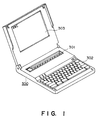
- Figure 1 is a schematic oblique view of an information processing apparatus comprising an embodiment of the recording apparatus according to the present invention.
- Figure 2 is a block diagram showing the electrical circuit structure of the information processing apparatus comprising the embodiment of the recording apparatus according to the present invention.
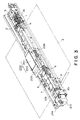
- Figure 3 is a schematic oblique view of an embodiment of the recording apparatus according to the present invention.
- Figure 4 is an oblique view of an embodiment of the recovery apparatus.
- FIG. 5 is a detailed drawing of an embodiment of the pump unit according to the present invention.
- Figure 6 is a schematic oblique view of embodiments of the cartridge type recording head and the carrier according to the present invention.
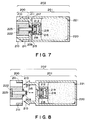
- Figure 7 is a sectional view of an embodiment of the recording cartridge, with the recording head portion and ink container portion being connected.
- Figure 8 is a sectional view of the embodiment of the recording cartridge, with the recording head portion and ink container portion being separated.
- Figure 9 is a recovery operation flow chart for the embodiment of the present invention.
- Figure 10 is a flow chart of the entire control sequence for exchanging the ink container in the first, second or third embodiment.
- Figure 11 is a flow chart of the operational control sequence for the recovery apparatus when the ink container of the first embodiment is exchanged.
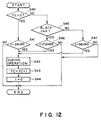
- Figure 12 is a flow chart of the operational control sequence for the recovery apparatus when the ink container of the second embodiment is exchanged.
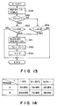
- Figure 13 is a flow chart of the operational control sequence for the recovery apparatus when the ink container of the third embodiment is exchanged.
- Figure 14 is a table showing the relation between the control timing for the operation of the recovery apparatus and a thermistor temperature T while the ink container of the third embodiment is exchanged.
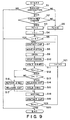
- Figure 15 is a flow chart for the sequence for the sucking and heating operations in the embodiments of the present invention.
- Figure 1 is a schematic oblique view of the external view of an information processing apparatus 300 comprising the recording apparatus according to the present invention.
- a reference numeral 301 designates a printer portion; 302, a key board portion comprising the keys for inputting letters, numbers, and other characters, and the keys for issuing various commands; and
- a reference numeral 303 designates a display portion comprising a display.
- FIG. 2 is a block diagram showing the electrical circuit structure of the information processing apparatus 300 according to the present invention.
- a reference numeral 401 designates a controller which constitutes recovery operation controlling means for controlling the recovery operation, which will be later described in detail, and also serves as the main controller;
- 402 a CPU in the form of, for example, a microcomputer, for carrying out given operational sequences;
- 403 a RAM comprising areas in which the text data or image data are developed or working areas;
- 404 a ROM storing programs corresponding to the aforementioned sequences or fixed data such as font data;
- 405 a timer needed when executable cycles for the CPU 402 are created or when images are recorded by the printer portion 301;
- a reference numeral 406 designates an interface portion for connecting the signals from the CPU 402 to the peripheral apparatuses.
- a reference numeral 407 designates a controller of the printer portion 301; 408, a heat detecting portion for detecting the recording head information such as presence or absence of the recording head 200, recording head types, output values of a sensor for detecting the temperature of the recording head 200, output values of a censor for detecting whether or not the ink is within the ink container 201; 409, a line buffer for storing the recording data for the recording head 200; 410, a head driver which supplies the recording head 200 with recording signals or electric power; 411a, 411b, and 411c, motor drivers for supplying signals and electric power necessary to driving a carrier motors 213, a sheet delivery motor 5, and an automatic sheet feeder motor 20, respectively; 412, a detecting portion for detecting the outputs of sensors such as a home position sensor 214 and a paper sensor 9; and a reference numeral 414 designates an ambient temperature detecting portion for detecting the output value of the sensor which detects the ambient temperatures of the apparatus and the recording head.
- an electric power source for supplying the above mentioned electrical circuit with the electrical power.
- this electrical power source a rechargeable battery, a disposable battery, or a converter for the AC power source employed when the main assembly of the information processing apparatus is installed in a stationary manner, are available.
- FIG 3 is a schematic oblique view of the printer portion of the ink jet apparatus shown in Figure 1.
- a carrier 203 mounted on a carrier 203 is a cartridge type recording head 202 in which a recording head 200 constituting the recording means and an ink container 201 are connected in a manner such that each of them can be individually replaced.
- the carrier 203 is engaged with a lead screw 208 on the side where the recording head 200 is, so as to be movable in the axis direction of the lead screw 203, and is provided with a guide on the other side, which is engaged with a guide rail 2 formed on a chassis 1 so as to slide in the direction parallel to the axis direction of the lead screw 203.
- the carrier 203 can be reciprocated in the axis direction of the lead screw 203.
- the recording head 200 is driven to eject ink in response to recording signals as well as in synchronization with the reciprocating movement of the carrier 203, whereby an image equivalent to a single line of recording is formed on a recording material 3.
- the recording material 3 is advanced by conveying means by a distance equivalent to a single line space to be prepared for the recording of the next line, wherein the advancement of this recording material 2 is carried out by a rotary pair of a conveyer roller 4 and a pinch roller 8 pressed thereon and another rotary pair of a discharger roller 7 and a spur roller 6.
- the conveyer roller 4 and discharge roller (unshown) are driven by a sheet delivery motor 4, wherein the driving force is transmitted through a reduction gear train 10.
- a reference numeral 9 designates a paper sensor for detecting the presence or absence of the recording material 3.
- Figure 4 is an oblique view of the recovery mechanism of the ink jet recording apparatus.
- the recovering mechanism comprises: a cap 101 for capping the ejection orifice surface of the recording head 200; a pump unit 108 for generating a negative pressure in the cap 101 so that the ink on the ejection orifice surface is sucked through the cap 101 to be delivered to a discharge ink absorbing member; a known cam for moving the cap 101 to and from the election orifice surface, for transmitting the driving force to the pump unit 108, and for driving a wiping mechanism for wiping the ink adhering to the ejection orifice surface; and a control gear 102 of the transmission mechanism comprising a gear train.
- a reference numeral 103 designates a blade, which wipes clean the ink ejecting surface of the recording head 200.
- the pump unit 108 is constructed in the form of a plunger pump as shown in Figure 5.
- a reference numeral 104 designate a cylinder comprising a cylinder portion 104a and a guide portion (unshown) for guiding a plunger 105 which will be described later, wherein a portion in the axial direction is cut away to form an ink passage; 104b, a cap lever holder formed in a manner so as to accommodate a cap lever seal; 104c, an ink sucking opening which opens at a predetermined location; 104d, discharge ink tube, the integrally formed end of which is inserted the discharge ink absorbing member; and a reference numeral 104e designates a parallel pin for opening or closing the cap, wherein when the parallel pin 104e is pushed by a cap opening/closing cam 102a of the control gear 102, the cylinder 104 rotates to open or close the cap 101, that is, to place the cap 101 firmly in contact with the ejection orifice surface of the recording head or separating it away.
- a reference numeral 106 designates a cap lever, wherein one end thereof, the ink guide (unshown), is pressed upon the cap lever seal 107 and the other end, a rotary shaft 106a, is snapped in a hole 104f of the cylinder 104, so that the cap lever can freely rotates.
- the ink guide of the cap lever 106 is pressed into the cap lever seal 107, and then the cap lever seal 107 is pressed into the cap lever holder 104b of the cylinder 104.
- FIG. 6 is a schematic oblique view of the separable-exchangeable cartridge and the carrier, the former being mounted on the latter.
- a reference numeral 200 designates a recording head which ejects ink in response to electric signals;
- 201 an ink container for storing the ink and supplying the ink to the recording head 200;
- 203 a carrier provided in the main assemble of the recording apparatus for holding the recording head 200 and ink container 201 and scanning the surface of the recording material;
- 204 a head lever for retaining or releasing the recording head;
- 205 an ink container lever for loading or unloading the ink container 201;
- 206 a head holder spring for securing the recording head 200 onto the carrier 203
- a reference numeral 207 designates a ink container case for holding the ink container 201.
- Figures 7 an 8 are schematic sectional views of the separable-exchangeable cartridge 202, wherein the recording 200 and ink container 201 are joined in Figure 7 and are separated in Figure 8.
- the recording head 200 comprises: an ink ejection orifices 222; an ink passage 223 for leading the ink to the ink ejection orifices 222; an ink supply tube 209 which is engaged with the ink container 201 so that the ink is supplied to the recording head 200; and a filter 215 provided within the ink passage 223 for preventing foreign matter or the like from reaching the ejection orifices. 222.
- the ink container 201 comprises: an ink absorbing member 220 for storing the ink; a valve mechanism 212 for opening or closing the port where the ink supply tube 209 is inserted, wherein the valve mechanism 212 further comprises an elastic sealing member 218 and a spring member 219 for generating a force to press the elastic sealing member toward the port (toward the left of the drawing); and a filter 216 provided at the interface between the valve mechanism and the ink absorbing member 220.
- the recording head 200 and ink container 201 are fixedly joined as claw members 210 provided in a pair on the ink container 210 are inserted into anchoring members 211 provided in a pair on the portions of the recording head 200.
- the ink supply tube 209 is inserted into the port of the ink container 201, pushing the elastic sealing member 218 of the valve mechanism 212 in the right direction of the drawing against the pressure of the spring member 219, whereby the leading end of the ink supply tube 209 is positioned within the ink container 201, enabling the ink to be supplied to the recording head 200.
- an O ring 217 is provided in a manner to fit around the ink supply tube 209 of the recording head 200, for preventing the ink from leaking out of the opening of the ink container while the recording head 200 and ink container 201 are in the joined state.
- the elastic sealing member 218 of the valve mechanism 212 closes the opening of the ink container 201, preventing thereby the ink from leaking out of the ink container 201.
- the filter 215 provided within the ink supply tube 209 of the recording head 200 comes in contact with the air as the ink container 201 is separated.
- the ink container 201 is exchanged with a fresh ink container 201, which is joined with the recording head 200 in the same manner as shown in Figure 7.
- a recovery sequence for exchanging the ink container will be described.
- a step S1 it is discriminated whether or not a sucking instruction is present. If there is, a step S2 is followed and if there is not, the sequence which will be described hereinafter is not followed, ending thereby the operation.
- the step S2 it is discriminated whether or not the present sucking instruction has been issued as a result of the detection of the ink container exchange.
- a step S3 is taken and if not, a step S7 is taken.
- a "0" is placed in an ink container exchange flag TC, and then, a step S7 is taken (when "O" is in the TC, it means that the ink container has not been exchanged).
- any generally conceivable means is acceptable.
- a microswitch or the like may be provided on the carrier 203 shown in Figure 3 or 6, on the surface where the ink container is placed, wherein each time the ink container is joined or disjoined, the output of this switch is reversed, indicating thereby the ink container exchange;
- a pair of a light emitter and a light receptor may be positioned across the carrier, adjacent to the carrier passage, wherein the discrimination is made by reading the output of the receptor which reverses depending on whether or not the light beam between the pair is interrupted; the discrimination may be made based on the weight of the recording head and ink container mounted on the carrier;
- a pair of electrodes may be positioned with a predetermined interval, in the ink passage, wherein the resistance value between the pair of electrodes is used for the discrimination of the ink container exchange; or many other various means.
- step S3 which is followed when it is determined in the step S2 that the ink sucking instruction has been issued after the ink tank exchange, "1" is placed in the ink container exchange flag TC (TC: tank change), and continuingly, in a step S4, a variable i is substituted by "1," wherein the variable i indicates the ordinal number of the sucking operation to be carried out next.
- step 5 it is discriminated whether or not the variable i is more than "3,” wherein when the variable i exceeds "3,” it is unnecessary to continue the sucking operation, stopping thereby the operation, and when the variable i does not exceed "3,” the step S7 is followed to carry out the sucking operation.
- variable i exceeds "3" means that more than three ink containers have been joined with the recording head. From the standpoint of the reliability of the recording head, the practical service life of the recording head in this embodiment is assumed to be equivalent to three ink containers full of ink. In other words, when the reliability of the recording head is further improved, the value with which the variable i is compared may be set higher.
- step S10 an operational sequence of the pump unit 150 is shown.
- step S11 the pump operation is suspended till the ink will have been completely sucked, whereby the ink sucking operation is prevented from being interrupted midway.
- step S12 it is discriminated whether the ink container exchange flag TC indicates "1" or "0.” If the TC does not show "1,” the sequence skips to a step S16 and if it shows "0,” the sequence advances to a step S13.
- step S13 it is discriminated whether or not the value of the variable i which indicates the ordinal number of the sucking operation is "1."
- the sequence jumps to the step S16 and if i is "1,” a step S14 is followed.
- the sucking operation to be carried out is the first one after the ink container exchange; therefore, immediately after the sucking operation is completed, the cap, having been covering the ejection orifice surface, is released in the step S14 and held released for three second in the step S15, whereby the ink having advanced through the interface between the ink container and recording head, halfway into the ink passage within the recording head is returned toward the ink container due to the negative pressure of the ink container, leaving practically no ink in the ink passage within the recording head.
- a metallic mesh filter is provided on the recording head side and the ink retaining force is generated by the meniscus of the ink formed in this filter; therefore, the ink does not retreat beyond this point toward the ink container.
- step S21 the value of the variable i, which indicates the ordinal number of the sucking operation, is increased by "1" and the sequence skips back to the step S5.
- the sequence jumps to the step S16, where even after the sucking operation is completed in the step S11, the cap is held for two seconds as it covers the ejection orifice surface. After recovering the state of full negative pressure in the pump unit and cap, the cap is released in a step S17.
- the number of consecutive sucking operation at the time of the ink container exchange and the duration in which the cap is held in contact with the ejection orifice surface may appropriately selected depending on the types of the ink jet cartridges or suction pumps, not being limited to the values indicated in Figure 15.
- the stable performance of the ink jet cartridge comprising an exchangeable ink container can be realized by improving slightly the operational sequence of the recovery suction pump, without leaving small bubbles in the ink stream when the ink container is joined (exchanged) and without wasteful ink consumption,
- the present invention can be an extremely effective means for downsizing the recording apparatuses in the future.
- the recovery operation described hereinbefore eliminates the presence of bubbles by a single sucking operation, but the presence of bubbles in the recording head can be more reliably eliminated by carrying out the recovery operation described hereinafter, which uses the changes in the states of the ink and bubbles with the passage of time.
- the first and second predetermined durations of time (Ta) and (Tb), which are the durations of time elapsed after the previous recovery operation was carried out, are 24 and 72 hours, respectively.
- a step S34 it is discriminated whether or not the ink container exchange flag TC is "0."
- that the TC is "0" means that a timer 405, a clocking means, is checked for the first time after the ink container exchange.
- This ink container exchange flag TC is processed within a non-volatile memory 413 shown in the block diagram of Figure 2.
- the clocking means is reset each time the recovery apparatus is operated.
- step S35 it is discriminated whether or nor the time t (elapsed time since the last recovery operation is carried out) of the timer, the clocking means exceeds 24 hours.
- the step S36 is taken, where the sucking operation as the second recovery operation is carried out by the pump shown in Figure 5 and then, a step S37 is followed.
- t does not exceed 24 hours in the step S37, this operation of sucking pump is ended.
- step S39 it is discriminated whether or not t exceeds 72 hours.
- the step S36 is followed where the sucking operation as the third recovery operation is performed and then the step S37 is followed.
- t is less than 72 hours, this operation of the sucking pump is ended.
- step S37 the value of the ink container exchange flag TC is increased by "1" and then a step S38 is followed.
- step S38 the clocking means t is reset to "0" and then this operation of the sucking pump is ended.
- the ink is first allowed to retreat to the ink container by releasing the cap after the first sucking operation and then the second sucking operation is carried out to fill the recording head.
- the recording head is basically filled with the ink in which no bubble are present but it is conceivable that bubbles of extremely small sizes may still present.
- an additional sucking operation that is, the third sucking operation, is carried out after the elapse of the predetermined duration of time, whereby the recording head is filled with the ink containing no bubbles.
- any known methods as follows is acceptable: a method in which the ink container and carrier are provided with one of a pair of electrodes, respectively, and the resistance value of the electrode on the ink container side is made different depending on the ink color, to discriminate the colors; a method in which a portion of the joint between the ink container and carrier is given a different shape depending on the ink color to discriminate the colors; or a like method.
- step S31 of Figure 10 After it is determined in a step S31 of Figure 10 that the ink container has been exchanged, the sequence moves to a step S32 where the sucking operation is carried out. In a step S33, which is the step after the sucking operation, "0" is placed in the ink container flag TC and this sequence is ended.
- the Ta is set at 24 hours and the Tb is set at 72 and 96 hours.
- a step S40 in Figure 12 it is discriminated whether or not the value of the ink container exchange flag TC is "0." When the TC is "0,” the sequence advances to a step S41, and when not, a step S45 is taken.
- step S41 it is discriminated whether or not the time t of the timer 405, the clocking means, is more than 24 hours. When it is over 24 hours, the sequence advances to a step S42 where the sucking operation is carried out and then a step S43 is followed. When in the step S41 the time t is not over 24 hours, this operation of sucking pump is ended.
- step S45 it is discriminated whether or not the ink color is black
- the sequence advances to a step S46, and when not, a step S47 is followed.
- step S46 it is discriminated whether or not the time t is more than 72 hours. When it is more than 72 hours, the sequence goes to a step S42 where the sucking operation is carried out and then the sequence goes to a step S43. When in the step S46 the time t is not more than 72 hours, this operation of the sucking pump is ended.
- step S47 it is discriminated whether or not the time t is more than 96 hours.
- the sequence advances to a step S42 where the sucking operation is carried out and then a step S43 is followed.
- step S47 the time t is not more than 96 hours, this operation of the sucking pump is ended.
- step S43 the value of the ink container exchange flag TC is increased by "1" and the sequence advances to a step S44.
- step S44 the clocking means t is reset to "0" and then this operation of the sucking pump is ended.
- the ink jet recording apparatus comprising the super-small recording head with separable-exchangeable ink container according to the present invention is used after it is left in an environment in which the temperature is as low as 5°C.
- the bubbles in the ink supply passage are not likely to grow. Therefore, when under this condition the recovery sequence as described in the preceding two embodiments is carried out as the control means for controlling the automatic recovery apparatus during the ink container exchange, the apparatus comes to be operated more times than necessary for the adequate recovery operation. As a result, the ink is going to be wasted.
- values A and B are the values of Ta and Tb, respectively, wherein Figure 14 is a table to be used for determining the values of Ta and Tb with reference to a temperature T detected by the aforementioned thermistor.
- the values A and B are selected according to the temperature T detected by the thermistor, referring to the table.
- step S49 it is discriminated whether or not the value of the ink container exchange flag is "0."
- the sequence advances to a step S50, and when not, a step 54 is followed.
- step S50 it is discriminated whether or not the time t is more than A hours (for example, when the value of the temperature T detected by the thermistor is 23°C, A is 24 hours). When it is more than A hours, the sequence advances to a step S51 where the sucking operation is carried out and then to a step S52. When the time t is not more than A hours, this operation of the sucking pump is ended.
- step S54 it is discriminated whether or not the time t is more than B hours. When it is more than B hours, the sequence goes to a step S51, where the sucking operation is carried out, and then to a step S52. When in the step S54 the time t is not more than B hours, this operation of sucking pump is ended.
- step S52 the value of the ink container exchange flag TC is increased by "1" and then the sequence moves to a step S53.
- step S53 the aforementioned clocking means t is reset to "0" and this operation of the sucking pump is ended.
- the time elapsing before the recovery apparatus is to be operated is set up in multiple steps; therefore, not only can the bubbles in the recording head be reliably discharged, but also the ink is prevented from being wastefully consumed, that is, consumed more than necessary, during the recovery operation.
- the ejection orifices are covered with the cap but it is not the case that the recording liquid is perfectly prevented from evaporating only because they are covered.
- the recording liquid cannot be completely prevent from evaporating; therefore, the recording liquid in these areas increases its viscosity or solidifies.
- the recovery operation is carried out under such a condition, even through it can flow the recording liquid itself, it cannot completely remove the recording liquid with the increased viscosity and the solidified recording liquid, which are present adjacent to the ejection orifices, failing thereby to recover sufficiently the recording head performance.
- sufficient recovery means that the recording head sufficiently regains its characteristics related to the direction in which the ink droplets are ejected and the amount by which the ink is ejected, during the recording operation following immediately after the recovery operation.
- the entire recording liquid within the system decreases its viscosity, which invites the decline in the flowability of the recording liquid during the recovery operation also. Therefore, it is possible that the satisfactory state of recovery cannot be accomplished by the recovery means which depends solely on the flow of the recording liquid, unless such a recovery operation is repeated for a while.
- the following steps may he taken: after closing the recording liquid sucking opening which is in communication with the ink jet recording head, the piston is moved in the vacuum pump constituting the recording liquid sucking apparatus, in order to create a state or vacuum within the cylinder of the pump, but just before the piston begins to be moved, the energy for ejecting the recording liquid is given, whereby the increased viscosity of the ink within the nozzles which have not been used before this operation can be reduced; the fluidity of the ink is increased by increasing the ink temperature.
- this energy is applied just before the recording liquid is made to actually flow, the application efficiency is extremely high.
- the piston movement and energy application are not allowed to occur at the same time; they are differentiated in terms of timing, which brings forth the following large effects. That is, when the piston of the suction pump is moved, a power source (mainly, a motor) is needed, and when the recording apparatus is small, the power consumed for moving the piston alone is relatively large, affording thereby little to be spared. Therefore, if the energy is applied while the piston is moved, the current demand may exceed the capacity of the apparatus. Thus, differentiating the timings for two actions is effective to preventing the current demand from exceeding the capacity of the power source. The smaller the apparatus is, the more important this point is.
- a power source mainly, a motor
- the amount of energy to be applied when the operation of the suction pump is not limited to once; when the operation is to be repeated several times, it does not need to be the same each time; such a method in which an appropriate amount of energy is selected in response to the state of each suction pump operation is more effective.
- the amount of energy may be differentiated between when the piston begins to be moved for reducing the internal pressure of the pump and when for discharging the recording liquid; various amounts of energy may be matched with each of the several operations repeated by the suction pump.
- the amount of energy to be applied may be determined in consideration of such factors as the structure of the recording head to be used; the ways the recording head is disposed in the apparatus; and ambient conditions such as temperature, humidity, or the like of the environment in which the recording apparatus is to be placed.
- Figure 15 is a flow chart showing the operational flow of this embodiment.
- step S61 after a command for sucking operation is issued, the cap is placed in contact with the ejection surface of the ink jet recording head .
- step S62 the piston is first moved in a J direction to discharge the ink within the pump chamber.
- the movement of the piston is stopped in a step S63.
- This stoppage of the piston is also a preparation for next movement, a reverse movement of the piston, and during this stoppage the power is supplied to the ink-ejecting exothermic elements of the ink jet recording head in a step S64; preheating occurs.
- the power is supplied in the form of 500 pulse signals.
- a step S65 is followed where the piston is moved in the reverse direction. And in a step S66, the piston is stopped as soon as the retainer of the piston passes the ink passage, and next in a step S67, the power is supplied to the ink-ejecting exothermal elements of the recording head, wherein the heating and sucking operations are simultaneously carried out. As soon as the sucking and heating are ended, a step S68 is followed where the cap is moved away from the ejection surface of the ink jet recording head.
- Table 1 Pre-heating Heating-while-sucking 500 500
- the timings for both preheating and heating-while-sucking operations are different from the timing for the rotation of the timing gear for driving the pump; while the heating goes on, the timing gear does not move. Therefore, it is unnecessary to increase the capacity of the power source. Further, the number of pulses for the preheating and heating-while-sucking operations have only to be set at an appropriate value according to the characteristics of the recording head and recording system.
- Table 2 shows various settings for the number of pulses for the preheating and heating-while-sucking operations while the recovery-by-sucking operation is carried out. The energy for heating can be more effectively used by selecting such settings. Table 2 Pre-heating Heating-while-sucking 500 1000
- this embodiment offers a system capable of recovering the performance of even the recording head in which the ink container may be frequently exchanged.
- An ink jet apparatus an ink jet head; an ink container for storing ink to be ejected out of the head; a carriage for mounting an exchangeable ink jet cartridge; a sucking device comprising a cap to be placed in contact with the head when the ink is to be sucked out of the recording head of the cartridge and a pump for generating a negative pressure, being connected to the cap; and a controller for controlling the sucking operation carried out by the sucking device; wherein the controller controls the cap to be held away from the head for a predetermined duration of time after carrying out the first sucking operation following the exchange of the ink container by covering the head with the cap.
Applications Claiming Priority (6)
| Application Number | Priority Date | Filing Date | Title |
|---|---|---|---|
| JP34743992A JPH06191054A (ja) | 1992-12-28 | 1992-12-28 | インクジェット記録装置 |
| JP347439/92 | 1992-12-28 | ||
| JP34743892A JP3119399B2 (ja) | 1992-12-28 | 1992-12-28 | インクジェット記録装置 |
| JP347438/92 | 1992-12-28 | ||
| JP16088993A JPH07132618A (ja) | 1993-06-30 | 1993-06-30 | インクジェット記録装置およびインクジェット記録ヘッドの吐出状態回復方法 |
| JP160889/93 | 1993-06-30 |
Publications (3)
| Publication Number | Publication Date |
|---|---|
| EP0604938A2 true EP0604938A2 (de) | 1994-07-06 |
| EP0604938A3 EP0604938A3 (de) | 1995-01-04 |
| EP0604938B1 EP0604938B1 (de) | 1997-05-07 |
Family
ID=27321760
Family Applications (1)
| Application Number | Title | Priority Date | Filing Date |
|---|---|---|---|
| EP93120922A Expired - Lifetime EP0604938B1 (de) | 1992-12-28 | 1993-12-27 | Tintenstrahlaufzeichnungsgerät und Rückgewinnungsverfahren dafür |
Country Status (4)
| Country | Link |
|---|---|
| US (1) | US6149261A (de) |
| EP (1) | EP0604938B1 (de) |
| AT (1) | ATE152671T1 (de) |
| DE (1) | DE69310488T2 (de) |
Cited By (4)
| Publication number | Priority date | Publication date | Assignee | Title |
|---|---|---|---|---|
| EP0736388A2 (de) * | 1995-04-07 | 1996-10-09 | Canon Kabushiki Kaisha | Tintenstrahldruckgerät |
| EP0755028A2 (de) * | 1995-06-19 | 1997-01-22 | Francotyp-Postalia Aktiengesellschaft & Co. | Anordnung für eine elektronische Handfrankiermaschine |
| EP0997286A1 (de) * | 1996-12-24 | 2000-05-03 | Seiko Epson Corporation | Tintenstrahlaufzeichnungsgerät |
| US6189997B1 (en) | 1995-08-30 | 2001-02-20 | Canon Kabushiki Kaisha | Uncapping ink jet heads |
Families Citing this family (8)
| Publication number | Priority date | Publication date | Assignee | Title |
|---|---|---|---|---|
| JP3718986B2 (ja) | 1997-04-03 | 2005-11-24 | ブラザー工業株式会社 | インクジェット記録装置 |
| JP3884878B2 (ja) | 1999-02-24 | 2007-02-21 | キヤノン株式会社 | 記録装置及び吸引回復制御方法 |
| US7547089B2 (en) * | 2004-03-23 | 2009-06-16 | Canon Kabushiki Kaisha | Ink jet recording apparatus |
| JP4859231B2 (ja) * | 2006-12-21 | 2012-01-25 | キヤノン株式会社 | インクジェット記録装置およびインク消費量算出方法 |
| US8191989B2 (en) * | 2009-04-28 | 2012-06-05 | Canon Kabushiki Kaisha | Printing apparatus and recovering method therefor |
| JP5921136B2 (ja) | 2011-10-21 | 2016-05-24 | キヤノン株式会社 | インクジェット記録装置および物流インクの排出方法 |
| JP5917083B2 (ja) | 2011-10-21 | 2016-05-11 | キヤノン株式会社 | インクジェット記録装置およびメンテナンス方法 |
| JP6045191B2 (ja) | 2012-05-21 | 2016-12-14 | キヤノン株式会社 | インクジェット記録装置および記録方法 |
Citations (4)
| Publication number | Priority date | Publication date | Assignee | Title |
|---|---|---|---|---|
| EP0448967A1 (de) * | 1990-02-26 | 1991-10-02 | Canon Kabushiki Kaisha | Tintenstrahlaufzeichnungsgerät und Verfahren zum Reinigen des Aufzeichnungskopfes |
| EP0535686A2 (de) * | 1991-10-03 | 1993-04-07 | Canon Kabushiki Kaisha | Tintenstrahlvorrichtung mit Möglichkeit zur Durchführung einer Rückgewinnungsoperation |
| JPH05169675A (ja) * | 1991-12-19 | 1993-07-09 | Canon Inc | インクジェット記録装置及びその回復方法 |
| EP0553561A2 (de) * | 1991-12-25 | 1993-08-04 | Canon Kabushiki Kaisha | Tintenstrahlaufzeichnungsvorrichtung |
Family Cites Families (14)
| Publication number | Priority date | Publication date | Assignee | Title |
|---|---|---|---|---|
| JPS52150029A (en) * | 1976-06-07 | 1977-12-13 | Konishiroku Photo Ind Co Ltd | Ink jet recording device |
| US4819012A (en) * | 1983-06-10 | 1989-04-04 | Canon Kabushiki Kaisha | Ink-jet printer with cap means |
| JPH089231B2 (ja) * | 1984-01-31 | 1996-01-31 | キヤノン株式会社 | 吐出回復方法 |
| US4999643A (en) * | 1984-11-19 | 1991-03-12 | Canon Kabushiki Kaisha | Discharge recovery device and apparatus having suction means and vent means communicating with capping means |
| US4745414A (en) * | 1986-04-09 | 1988-05-17 | Canon Kabushiki Kaisha | Recovery device for an ink jet recorder and a recovery method thereof |
| JP2522770B2 (ja) * | 1986-08-05 | 1996-08-07 | キヤノン株式会社 | インクジェット装置 |
| US5068674A (en) * | 1988-06-07 | 1991-11-26 | Canon Kabushiki Kaisha | Liquid jet recording head stabilization |
| US5109233A (en) * | 1988-06-08 | 1992-04-28 | Canon Kabushiki Kaisha | Method of discharging liquid during a discharge stabilizing process and an ink jet recording head and apparatus using same |
| DE69029780T2 (de) * | 1989-08-31 | 1997-07-10 | Canon Kk | Absaug-Regeneriervorrichtung für ein Tintenstrahlaufzeichnungsgerät |
| US5148203A (en) * | 1989-09-18 | 1992-09-15 | Canon Kabushiki Kaisha | Ink jet recording apparatus including a drive mechanism for an ink ejection recovery systems |
| SG73428A1 (en) * | 1990-02-28 | 2000-06-20 | Canon Kk | An ink jet apparatus |
| US5103244A (en) * | 1990-07-05 | 1992-04-07 | Hewlett-Packard Company | Method and apparatus for cleaning ink-jet printheads |
| JPH0531909A (ja) * | 1991-07-26 | 1993-02-09 | Canon Inc | インクジエツト記録装置 |
| CA2085550C (en) * | 1991-12-19 | 1999-07-06 | Kentaro Yano | Method of controlling an ink-jet recording apparatus according to recording head information, and ink-jet recording apparatus in which the method is implemented |
-
1993
- 1993-12-27 EP EP93120922A patent/EP0604938B1/de not_active Expired - Lifetime
- 1993-12-27 AT AT93120922T patent/ATE152671T1/de not_active IP Right Cessation
- 1993-12-27 DE DE69310488T patent/DE69310488T2/de not_active Expired - Lifetime
-
1996
- 1996-08-13 US US08/689,684 patent/US6149261A/en not_active Expired - Lifetime
Patent Citations (4)
| Publication number | Priority date | Publication date | Assignee | Title |
|---|---|---|---|---|
| EP0448967A1 (de) * | 1990-02-26 | 1991-10-02 | Canon Kabushiki Kaisha | Tintenstrahlaufzeichnungsgerät und Verfahren zum Reinigen des Aufzeichnungskopfes |
| EP0535686A2 (de) * | 1991-10-03 | 1993-04-07 | Canon Kabushiki Kaisha | Tintenstrahlvorrichtung mit Möglichkeit zur Durchführung einer Rückgewinnungsoperation |
| JPH05169675A (ja) * | 1991-12-19 | 1993-07-09 | Canon Inc | インクジェット記録装置及びその回復方法 |
| EP0553561A2 (de) * | 1991-12-25 | 1993-08-04 | Canon Kabushiki Kaisha | Tintenstrahlaufzeichnungsvorrichtung |
Non-Patent Citations (1)
| Title |
|---|
| PATENT ABSTRACTS OF JAPAN vol. 17, no. 576 (M-1499) 20 October 1993 & JP-A-05 169 675 (CANON INC.) 9 July 1993 * |
Cited By (9)
| Publication number | Priority date | Publication date | Assignee | Title |
|---|---|---|---|---|
| EP0736388A2 (de) * | 1995-04-07 | 1996-10-09 | Canon Kabushiki Kaisha | Tintenstrahldruckgerät |
| EP0736388A3 (de) * | 1995-04-07 | 1997-11-05 | Canon Kabushiki Kaisha | Tintenstrahldruckgerät |
| US5988782A (en) * | 1995-04-07 | 1999-11-23 | Canon Kabushiki Kaisha | Ink-jet printing apparatus |
| US6488348B1 (en) | 1995-04-07 | 2002-12-03 | Canon Kabushiki Kaisha | Ink-jet printing apparatus |
| EP0755028A2 (de) * | 1995-06-19 | 1997-01-22 | Francotyp-Postalia Aktiengesellschaft & Co. | Anordnung für eine elektronische Handfrankiermaschine |
| EP0755028A3 (de) * | 1995-06-19 | 1999-12-29 | Francotyp-Postalia Aktiengesellschaft & Co. | Anordnung für eine elektronische Handfrankiermaschine |
| US6189997B1 (en) | 1995-08-30 | 2001-02-20 | Canon Kabushiki Kaisha | Uncapping ink jet heads |
| EP0997286A1 (de) * | 1996-12-24 | 2000-05-03 | Seiko Epson Corporation | Tintenstrahlaufzeichnungsgerät |
| US6305778B1 (en) | 1996-12-24 | 2001-10-23 | Seiko Epson Corporation | Ink-jet recording apparatus |
Also Published As
| Publication number | Publication date |
|---|---|
| DE69310488D1 (de) | 1997-06-12 |
| EP0604938B1 (de) | 1997-05-07 |
| DE69310488T2 (de) | 1997-12-04 |
| EP0604938A3 (de) | 1995-01-04 |
| US6149261A (en) | 2000-11-21 |
| ATE152671T1 (de) | 1997-05-15 |
Similar Documents
| Publication | Publication Date | Title |
|---|---|---|
| KR970004232B1 (ko) | 잉크 로딩 장치, 이를 갖는 기록 장치 및 잉크 로딩 방법 | |
| EP0674996B1 (de) | Abdeckverfahren für Farbstrahlaufzeichnungsvorrichtung | |
| EP1147904B1 (de) | Verbindungsvorrichtung, Tintenstrahlaufzeichnungsgerät mit dieser Vorrichtung, und Tintenversorgungsvorrichtung und -verfahren | |
| US5917518A (en) | Ink jet recording apparatus with support for recording head carriage | |
| EP0604938B1 (de) | Tintenstrahlaufzeichnungsgerät und Rückgewinnungsverfahren dafür | |
| JPH11188890A (ja) | 液体補充方法及び該方法を用いた液体吐出記録装置 | |
| EP0931662A2 (de) | Tintenstrahldrucker und sein Steuerverfahren | |
| KR19990014295A (ko) | 잉크젯 프린터 | |
| JP2008238787A (ja) | 液体供給システム、液体供給装置、および液体供給方法 | |
| EP1080915B1 (de) | Flüssigkeitausstosskopfeinheit | |
| EP1080929B1 (de) | Flüssigkeitsdruckkopf, Drucker, und Verfahren zum positionieren des Flüssigkeitsdruckkopfs im Drucker | |
| JP3363760B2 (ja) | インク供給装置およびプリント装置 | |
| US7201465B2 (en) | Ink jet printing apparatus | |
| JPH04140146A (ja) | インクジェット記録装置 | |
| JP2002137418A (ja) | インクジェット式記録装置 | |
| JP2005022200A (ja) | インクジェット記録装置 | |
| JP2675909B2 (ja) | インクジェット記録装置 | |
| JP4401493B2 (ja) | プリント装置 | |
| JPH0825653A (ja) | インクジェットプリント装置 | |
| JP4089147B2 (ja) | インクジェット記録装置 | |
| JPH0717058A (ja) | インクジェット記録装置 | |
| JP3978995B2 (ja) | インクジェット記録装置 | |
| EP1199175B1 (de) | Flüssigkeitsausstossgerät und Ausstossrückgewinnungsverfahren | |
| JP2675908B2 (ja) | インクジェット記録装置 | |
| JP2698698B2 (ja) | 吸引ポンプおよびそれを用いるインクジェット記録装置 |
Legal Events
| Date | Code | Title | Description |
|---|---|---|---|
| PUAI | Public reference made under article 153(3) epc to a published international application that has entered the european phase |
Free format text: ORIGINAL CODE: 0009012 |
|
| 17P | Request for examination filed |
Effective date: 19931227 |
|
| AK | Designated contracting states |
Kind code of ref document: A2 Designated state(s): AT BE CH DE DK ES FR GB GR IE IT LI LU NL PT SE |
|
| PUAL | Search report despatched |
Free format text: ORIGINAL CODE: 0009013 |
|
| AK | Designated contracting states |
Kind code of ref document: A3 Designated state(s): AT BE CH DE DK ES FR GB GR IE IT LI LU NL PT SE |
|
| GRAG | Despatch of communication of intention to grant |
Free format text: ORIGINAL CODE: EPIDOS AGRA |
|
| 17Q | First examination report despatched |
Effective date: 19960308 |
|
| GRAH | Despatch of communication of intention to grant a patent |
Free format text: ORIGINAL CODE: EPIDOS IGRA |
|
| GRAH | Despatch of communication of intention to grant a patent |
Free format text: ORIGINAL CODE: EPIDOS IGRA |
|
| GRAA | (expected) grant |
Free format text: ORIGINAL CODE: 0009210 |
|
| AK | Designated contracting states |
Kind code of ref document: B1 Designated state(s): AT BE CH DE DK ES FR GB GR IE IT LI LU NL PT SE |
|
| PG25 | Lapsed in a contracting state [announced via postgrant information from national office to epo] |
Ref country code: NL Free format text: LAPSE BECAUSE OF FAILURE TO SUBMIT A TRANSLATION OF THE DESCRIPTION OR TO PAY THE FEE WITHIN THE PRESCRIBED TIME-LIMIT Effective date: 19970507 Ref country code: LI Effective date: 19970507 Ref country code: GR Free format text: LAPSE BECAUSE OF FAILURE TO SUBMIT A TRANSLATION OF THE DESCRIPTION OR TO PAY THE FEE WITHIN THE PRESCRIBED TIME-LIMIT Effective date: 19970507 Ref country code: ES Free format text: THE PATENT HAS BEEN ANNULLED BY A DECISION OF A NATIONAL AUTHORITY Effective date: 19970507 Ref country code: DK Effective date: 19970507 Ref country code: CH Effective date: 19970507 Ref country code: BE Effective date: 19970507 Ref country code: AT Effective date: 19970507 |
|
| REF | Corresponds to: |
Ref document number: 152671 Country of ref document: AT Date of ref document: 19970515 Kind code of ref document: T |
|
| REG | Reference to a national code |
Ref country code: CH Ref legal event code: EP |
|
| ITF | It: translation for a ep patent filed |
Owner name: SOCIETA' ITALIANA BREVETTI S.P.A. |
|
| REF | Corresponds to: |
Ref document number: 69310488 Country of ref document: DE Date of ref document: 19970612 |
|
| ET | Fr: translation filed | ||
| REG | Reference to a national code |
Ref country code: IE Ref legal event code: FG4D Free format text: 73786 |
|
| PG25 | Lapsed in a contracting state [announced via postgrant information from national office to epo] |
Ref country code: SE Effective date: 19970807 Ref country code: PT Effective date: 19970807 |
|
| NLV1 | Nl: lapsed or annulled due to failure to fulfill the requirements of art. 29p and 29m of the patents act | ||
| REG | Reference to a national code |
Ref country code: CH Ref legal event code: PL |
|
| PG25 | Lapsed in a contracting state [announced via postgrant information from national office to epo] |
Ref country code: LU Free format text: LAPSE BECAUSE OF NON-PAYMENT OF DUE FEES Effective date: 19971227 Ref country code: IE Free format text: LAPSE BECAUSE OF NON-PAYMENT OF DUE FEES Effective date: 19971227 |
|
| PLBE | No opposition filed within time limit |
Free format text: ORIGINAL CODE: 0009261 |
|
| STAA | Information on the status of an ep patent application or granted ep patent |
Free format text: STATUS: NO OPPOSITION FILED WITHIN TIME LIMIT |
|
| 26N | No opposition filed | ||
| REG | Reference to a national code |
Ref country code: GB Ref legal event code: IF02 |
|
| PGFP | Annual fee paid to national office [announced via postgrant information from national office to epo] |
Ref country code: IT Payment date: 20081220 Year of fee payment: 16 |
|
| PGFP | Annual fee paid to national office [announced via postgrant information from national office to epo] |
Ref country code: FR Payment date: 20081222 Year of fee payment: 16 |
|
| REG | Reference to a national code |
Ref country code: FR Ref legal event code: ST Effective date: 20100831 |
|
| PG25 | Lapsed in a contracting state [announced via postgrant information from national office to epo] |
Ref country code: FR Free format text: LAPSE BECAUSE OF NON-PAYMENT OF DUE FEES Effective date: 20091231 |
|
| PG25 | Lapsed in a contracting state [announced via postgrant information from national office to epo] |
Ref country code: IT Free format text: LAPSE BECAUSE OF NON-PAYMENT OF DUE FEES Effective date: 20091227 |
|
| PGFP | Annual fee paid to national office [announced via postgrant information from national office to epo] |
Ref country code: GB Payment date: 20101223 Year of fee payment: 18 |
|
| PGFP | Annual fee paid to national office [announced via postgrant information from national office to epo] |
Ref country code: DE Payment date: 20101231 Year of fee payment: 18 |
|
| GBPC | Gb: european patent ceased through non-payment of renewal fee |
Effective date: 20121227 |
|
| REG | Reference to a national code |
Ref country code: DE Ref legal event code: R119 Ref document number: 69310488 Country of ref document: DE Effective date: 20130702 |
|
| PG25 | Lapsed in a contracting state [announced via postgrant information from national office to epo] |
Ref country code: DE Free format text: LAPSE BECAUSE OF NON-PAYMENT OF DUE FEES Effective date: 20130702 |
|
| PG25 | Lapsed in a contracting state [announced via postgrant information from national office to epo] |
Ref country code: GB Free format text: LAPSE BECAUSE OF NON-PAYMENT OF DUE FEES Effective date: 20121227 |