EP0602038B1 - Procede et appareil servant a usiner des engrenages droits et des engrenages helicoidaux - Google Patents
Procede et appareil servant a usiner des engrenages droits et des engrenages helicoidaux Download PDFInfo
- Publication number
- EP0602038B1 EP0602038B1 EP92906389A EP92906389A EP0602038B1 EP 0602038 B1 EP0602038 B1 EP 0602038B1 EP 92906389 A EP92906389 A EP 92906389A EP 92906389 A EP92906389 A EP 92906389A EP 0602038 B1 EP0602038 B1 EP 0602038B1
- Authority
- EP
- European Patent Office
- Prior art keywords
- tool
- grinding wheel
- gear
- width
- stock removing
- Prior art date
- Legal status (The legal status is an assumption and is not a legal conclusion. Google has not performed a legal analysis and makes no representation as to the accuracy of the status listed.)
- Expired - Lifetime
Links
- 238000000034 method Methods 0.000 title claims abstract description 72
- 238000003754 machining Methods 0.000 title claims description 17
- 238000000227 grinding Methods 0.000 claims abstract description 144
- 239000003082 abrasive agent Substances 0.000 claims description 2
- 239000000463 material Substances 0.000 claims description 2
- 239000011248 coating agent Substances 0.000 claims 1
- 238000000576 coating method Methods 0.000 claims 1
- 230000008569 process Effects 0.000 abstract description 42
- 206010006514 bruxism Diseases 0.000 abstract 1
- 230000008901 benefit Effects 0.000 description 7
- 230000008859 change Effects 0.000 description 4
- 229910003460 diamond Inorganic materials 0.000 description 4
- 239000010432 diamond Substances 0.000 description 4
- 239000002826 coolant Substances 0.000 description 3
- LOAGCJGEULMKRJ-UHFFFAOYSA-N Fragin Natural products CCCCCCCC(=O)NCC(C(C)C)N(O)N=O LOAGCJGEULMKRJ-UHFFFAOYSA-N 0.000 description 2
- 230000001419 dependent effect Effects 0.000 description 2
- 238000007747 plating Methods 0.000 description 2
- 230000004044 response Effects 0.000 description 2
- 229910052582 BN Inorganic materials 0.000 description 1
- PZNSFCLAULLKQX-UHFFFAOYSA-N Boron nitride Chemical compound N#B PZNSFCLAULLKQX-UHFFFAOYSA-N 0.000 description 1
- 230000009471 action Effects 0.000 description 1
- 238000005520 cutting process Methods 0.000 description 1
- 230000003247 decreasing effect Effects 0.000 description 1
- 230000007812 deficiency Effects 0.000 description 1
- 230000008021 deposition Effects 0.000 description 1
- 238000004519 manufacturing process Methods 0.000 description 1
- 230000007246 mechanism Effects 0.000 description 1
- 230000004048 modification Effects 0.000 description 1
- 238000012986 modification Methods 0.000 description 1
- TWNQGVIAIRXVLR-UHFFFAOYSA-N oxo(oxoalumanyloxy)alumane Chemical compound O=[Al]O[Al]=O TWNQGVIAIRXVLR-UHFFFAOYSA-N 0.000 description 1
- 238000002360 preparation method Methods 0.000 description 1
- 230000001360 synchronised effect Effects 0.000 description 1
Images


Classifications
-
- B—PERFORMING OPERATIONS; TRANSPORTING
- B23—MACHINE TOOLS; METAL-WORKING NOT OTHERWISE PROVIDED FOR
- B23F—MAKING GEARS OR TOOTHED RACKS
- B23F1/00—Making gear teeth by tools of which the profile matches the profile of the required surface
- B23F1/02—Making gear teeth by tools of which the profile matches the profile of the required surface by grinding
- B23F1/023—Making gear teeth by tools of which the profile matches the profile of the required surface by grinding the tool being a grinding worm
-
- B—PERFORMING OPERATIONS; TRANSPORTING
- B23—MACHINE TOOLS; METAL-WORKING NOT OTHERWISE PROVIDED FOR
- B23F—MAKING GEARS OR TOOTHED RACKS
- B23F23/00—Accessories or equipment combined with or arranged in, or specially designed to form part of, gear-cutting machines
- B23F23/006—Equipment for synchronising movement of cutting tool and workpiece, the cutting tool and workpiece not being mechanically coupled
-
- B—PERFORMING OPERATIONS; TRANSPORTING
- B23—MACHINE TOOLS; METAL-WORKING NOT OTHERWISE PROVIDED FOR
- B23F—MAKING GEARS OR TOOTHED RACKS
- B23F23/00—Accessories or equipment combined with or arranged in, or specially designed to form part of, gear-cutting machines
- B23F23/12—Other devices, e.g. tool holders; Checking devices for controlling workpieces in machines for manufacturing gear teeth
- B23F23/1225—Arrangements of abrasive wheel dressing devices on gear-cutting machines
- B23F23/1231—Arrangements of abrasive wheel dressing devices on gear-cutting machines using a gear-shaped dressing tool
-
- B—PERFORMING OPERATIONS; TRANSPORTING
- B23—MACHINE TOOLS; METAL-WORKING NOT OTHERWISE PROVIDED FOR
- B23F—MAKING GEARS OR TOOTHED RACKS
- B23F23/00—Accessories or equipment combined with or arranged in, or specially designed to form part of, gear-cutting machines
- B23F23/12—Other devices, e.g. tool holders; Checking devices for controlling workpieces in machines for manufacturing gear teeth
- B23F23/1237—Tool holders
- B23F23/1275—Grinding or honing worm holders
-
- B—PERFORMING OPERATIONS; TRANSPORTING
- B24—GRINDING; POLISHING
- B24B—MACHINES, DEVICES, OR PROCESSES FOR GRINDING OR POLISHING; DRESSING OR CONDITIONING OF ABRADING SURFACES; FEEDING OF GRINDING, POLISHING, OR LAPPING AGENTS
- B24B53/00—Devices or means for dressing or conditioning abrasive surfaces
- B24B53/06—Devices or means for dressing or conditioning abrasive surfaces of profiled abrasive wheels
- B24B53/08—Devices or means for dressing or conditioning abrasive surfaces of profiled abrasive wheels controlled by information means, e.g. patterns, templets, punched tapes or the like
- B24B53/085—Devices or means for dressing or conditioning abrasive surfaces of profiled abrasive wheels controlled by information means, e.g. patterns, templets, punched tapes or the like for workpieces having a grooved profile, e.g. gears, splined shafts, threads, worms
-
- Y—GENERAL TAGGING OF NEW TECHNOLOGICAL DEVELOPMENTS; GENERAL TAGGING OF CROSS-SECTIONAL TECHNOLOGIES SPANNING OVER SEVERAL SECTIONS OF THE IPC; TECHNICAL SUBJECTS COVERED BY FORMER USPC CROSS-REFERENCE ART COLLECTIONS [XRACs] AND DIGESTS
- Y10—TECHNICAL SUBJECTS COVERED BY FORMER USPC
- Y10T—TECHNICAL SUBJECTS COVERED BY FORMER US CLASSIFICATION
- Y10T409/00—Gear cutting, milling, or planing
- Y10T409/10—Gear cutting
- Y10T409/101431—Gear tooth shape generating
- Y10T409/103816—Milling with radial faced tool
- Y10T409/103975—Process
-
- Y—GENERAL TAGGING OF NEW TECHNOLOGICAL DEVELOPMENTS; GENERAL TAGGING OF CROSS-SECTIONAL TECHNOLOGIES SPANNING OVER SEVERAL SECTIONS OF THE IPC; TECHNICAL SUBJECTS COVERED BY FORMER USPC CROSS-REFERENCE ART COLLECTIONS [XRACs] AND DIGESTS
- Y10—TECHNICAL SUBJECTS COVERED BY FORMER USPC
- Y10T—TECHNICAL SUBJECTS COVERED BY FORMER US CLASSIFICATION
- Y10T409/00—Gear cutting, milling, or planing
- Y10T409/10—Gear cutting
- Y10T409/107791—Using rotary cutter
- Y10T409/10795—Process
Definitions
- the present invention is directed to a machine and process for machining workpieces utilizing a tool having a generally hourglass shape along the width thereof and at least one stock removing surface arranged and spaced along the tool width.
- the process includes rotating the grinding wheel about its axis which in turn causes a theoretical ring gear to rotate about its axis.
- a work gear is rotated about its axis and brought into mesh with the internal tooth surfaces of the rotating theoretical ring gear.
- the work gear is traversed in mesh relatively across the width of the grinding wheel in a plane substantially perpendicular to the axis of rotation of the work gear.
- the present invention enables inter alia usable, non-concave tooth surfaces to be formed on the work gear because it is characterized by the stock removing surface having a continually changing profile shape in a direction along that surface.
- the method of the present invention may be computer controlled and carried out on a machine having a plurality of computer controlled axes for positioning and operatively engaging a tool with a work gear.
- the method comprises computing rotational speeds and initial positions of the tool and the work gear in response to setup parameters input to the machine whereby the rotation of the tool is synchronized with the rotation of the work gear as though both were rotating in mesh with a rotating theoretical ring gear.
- Computing further operating positions of the axes in response to operating parameters input to the machine.
- Moving the computer controlled axes to the further operating positions includes, substantially simultaneously with the rotation, moving the computer controlled axes to traverse the work gear in mesh along a path relatively across the width of the tool in a plane perpendicular to the axis of rotation of the work gear.
- the steps of computing further operating positions and moving the computer controlled axes to the further operating positions are repeated for completing the machining operation.
- the present process allows a range of work gears to be machined with a single grinding wheel and permits gears having larger face widths to be machined.
- Another advantage of the present process is that any instant, the area of engagement between the work gear and grinding wheel is relatively small which means that forces acting on the machine are also small.
- contact between the work gear and grinding wheel is instantaneous point contact (through possibly at two points) which generates less heat and provides better coolant access.
- the inventive process also allows a greater portion of the width of the grinding wheel to be utilized in the grinding process.
- the present invention also includes a method of dressing a grinding wheel having a generally hourglass shape along the width thereof.
- the dressing is similar to the grinding process except for minor dimensional changes in the geometry of the dressing tool compared to the geometry of the desired work gear.
- Figure 1 illustrates a stock removing tool such as a grinding wheel 2 having an axis of rotation 5 and a width extending in the axial direction of the grinding wheel.
- the grinding wheel 2 comprises a generally hourglass shape along its width and is made of a suitable abrasive material such as aluminum oxide or cubic boron nitride (CBN).
- CBN cubic boron nitride
- the grinding wheel 2 has a diameter and at least one stock removing surface 3 generally helically arranged around the periphery thereof and extending along its width.
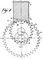
- the rotational speed of the work gear 8 will necessarily be greater than the speed of the theoretical ring gear 6. It is to be noted that although the rotations of the theoretical ring gear 6 and the work gear 8 are shown to be in a clockwise direction, the present invention is not limited to a particular direction of rotation. A particular direction of rotation is shown for reference purposes only.
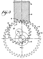
- FIG. 3 shows the position of the work gear 2 at the beginning of the grinding process. The traversal is necessary since, at the position shown in Figure 3, only limited tooth surface contact will occur between the work gear 8 and grinding wheel 2 in this position.
- the work gear 8 meshes with the grinding wheel 2 as the former is traversed in a plane substantially perpendicular to the axis of rotation of the work gear 8.
- the path of traversal is controlled by moving the center of the work gear, X W , in a path about the center, X I , of the theoretical ring gear 6.
- the path taken by the work gear 8 may be circular such as shown by Figure 3 wherein the work gear center, X W , moves about the center, X I , of the theoretical ring gear 6 at a constant radius, R.
- the path of the work gear need not be limited to circular movement.
- Axes 48 (Y-axis) and 72 (X-axis) are arranged perpendicular to each other. It can be seen that the direction of movement of the tool housing 30 and work spindle housing 60 could be reversed, that is, tool housing 30 could move in the X direction and work spindle housing 60 could move in the Y direction. Also, either the tool housing 30 or the work spindle housing 60 could move in both X and Y directions.
- the present inventive grinding process is not limited, as in the prior art plunge-type processes, to decreasing the face width capable of being machined on a work gear as the number of teeth decrease on a work gear.
- the present process also allows a greater portion of the grinding wheel to be utilized during grinding. This is primarily due to the circumferential direction of feeding the work gear into the grinding wheel in contrast to the radial feed direction of the prior art methods.
Landscapes
- Engineering & Computer Science (AREA)
- Mechanical Engineering (AREA)
- Grinding-Machine Dressing And Accessory Apparatuses (AREA)
- Polishing Bodies And Polishing Tools (AREA)
Abstract
Claims (17)
- Procédé pour usiner des engrenages droits et hélicoïdaux, ledit procédé comprenant les étapes consistant à :prévoir un outil d'enlèvement de matériau (2) ayant un axe de rotation (5), une largeur s'étendant dans la direction axiale dudit outil d'enlèvement de matériau et un diamètre, ledit outil d'enlèvement de matériau (2) ayant une forme généralement en sablier le long de ladite largeur et comportant au moins une surface d'enlèvement de matériau (3) agencée généralement hélicoïdalement autour de l'axe et s'étendant le long de ladite largeur dudit outil d'enlèvement de matériau, ladite au moins une surface d'enlèvement de matériau étant conjuguée le long de l'ensemble de ladite largeur avec des surfaces de dents (4) d'un engrenage annulaire théorique (6), faire tourner un engrenage comme pièce (8) ayant un axe de rotation (Xw) et ayant un diamètre inférieur au diamètre dudit engrenage annulaire théorique autour de son axe de rotation,faire tourner ledit outil d'enlèvement de matériau (2) autour de son axe de rotation, ledit engrenage annulaire théorique (6) tournant en engrènement avec ledit outil d'enlèvement de matériau,faire traverser ledit engrenage tournant (8) relativement sur ladite largeur dudit outil d'enlèvement de matériau, ladite traversée comprenant la rotation dudit engrenage à une vitesse où il engrène avec les surfaces dentées internes dudit engrenage annulaire théorique tournant et déplacer simultanément ledit engrenage le long d'un trajet autour du centre (X1) dudit engrenage annulaire théorique par quoi ledit engrenage traverse en engrènement avec ladite au moins une surface d'enlèvement de matériau relativement sur ladite largeur dudit outil d'enlèvement de matériau,
caractérisé en ce que ladite surface d'enlèvement de matériau a une forme de profil qui change continuellement dans une direction le long de ladite surface d'enlèvement de matériau agencée généralement helicoïdalement. - Procédé selon la revendication 1, où ledit trajet autour dudit centre dudit engrenage annulaire théorique est un trajet sensiblement circulaire.
- Procédé selon la revendication 1, où ladite au moins une surface d'enlèvement de matériau en forme de fil enlève simultanément du matériau des côtés opposés des dents adjacentes dudit engrenage comme pièce.
- Procédé selon la revendication 1, où ledit outil d'enlèvement de matériau est une meule.
- Procédé selon la revendication 1, où les engrenages usinés comprennent une courbure de dents longitudinales non concaves.
- Procédé de dressage d'une meule (2) pour meuler des surfaces de dents à obtenir sur des engrenages droits et hélicoïdaux, ladite meule ayant un axe de rotation, une largeur s'étendant dans la direction axiale de ladite meule et un diamètre, ladite meule ayant une forme généralement en sablier le long de ladite largeur avec au moins une surface de meulage agencée généralement hélicoïdalement et s'étendant le long de ladite largeur de ladite meule, ledit procédé comportant les étapes consistant à :prévoir un outil à dresser avec un axe de rotation et plusieurs surfaces de dents, ledit outil à dresser ayant essentiellement les mêmes spécifications qu'un engrenage (8) comme pièce à obtenir et comportant un revêtement en un matériau abrasif dur sur lesdites surfaces de dents,faire tourner ledit outil à dresser autour de son axe de rotation,faire tourner ladite meule (2) autour de son axe de rotation, ledit engrenage annulaire théorique tournant en engrènement avec ladite meule,faire traverser ledit outil à dresser tournant relativement sur ladite largeur de ladite meule dans un plan sensiblement perpendiculaire audit axe de rotation dudit outil à dresser, ladite traversée comprenant la rotation dudit outil à dresser à une vitesse où il engrène avec les surfaces de dents internes dudit engrenage annulaire théorique tournant et déplacer simultanément ledit outil à dresser le long d'un trajet autour du centre dudit engrenage théorique par quoi ledit outil à dresser traverse en engrènement avec ladite au moins une surface de meulage relativement sur ladite largeur de ladite meule,
caractérisé en ce que la surface de meulage a une forme de profil qui change continuellement dans la direction le long de ladite surface d'enlèvement de matériau agencée généralement hélicoïdalement. - Procédé selon la revendication 6, où ledit outil à dresser comprend les mêmes spécifications que ledit engrenage comme pièce à obtenir excepté que ledit outil à dresser a une dimension de creux plus petite et une dimension de saillie plus grande que ledit engrenage comme pièce à obtenir.
- Procédé selon la revendication 6, où ledit trajet autour dudit centre dudit engrenage annulaire théorique est un trajet sensiblement circulaire.
- Procédé selon la revendication 6, où ledit outil à dresser a un nombre de dents différent dudit engrenage comme pièce à obtenir.
- Procédé selon la revendication 9, où ledit outil à dresser a moins de dents que ledit engrenage comme pièce à obtenir.
- Appareil (20) pour usiner des surfaces de dents d'engrenages droits et hélicoïdaux, ledit appareil comprenant :une base d'usinage (2),un boîtier d'outil (30) situé sur ladite base d'usinage, ledit boîtier d'outil comportant un outil d'enlèvement de matériau (2) pouvant tourner autour d'un axe (5), ledit outil d'enlèvement de matériau ayant une largeur s'étendant dans sa direction axiale, ledit outil d'enlèvement de matériau ayant une forme généralement en sablier le long de ladite largeur et comprenant au moins une surface d'enlèvement de matériau (3) agencée généralement helicoïdalement et s'étendant le long de ladite largeur dudit outil d'enlèvement de matériau, ledit outil d'enlèvement de matériau étant fixé relâchablement dans un tambour tournant (44) dans ledit boîtier d'outil, ledit tambour tournant étant ajustable de manière tournante pour régler un angle d'hélice d'usinage dudit outil d'enlèvement de matériau,un boîtier de broche porte-pièces (60) situé sur ladite base d'usinage (22), ledit boîtier de broche porte-pièces comprenant un moyen de retenue de pièces (62) pour monter de manière rotative au moins une pièce d'oeuvre sur celui-ci en vue d'une rotation autour de son axe de rotation,des moyens (50, 52; 74) pour déplacer simultanément ledit boîtier d'outil et ledit boîtier de broche porte-pièces l'un par rapport à l'autre dans des directions mutuellement perpendiculaires (X, Y) par quoi ladite au moins une pièce traverse le long d'un trajet prédéterminé relativement sur ladite forme généralement en sablier dudit outil d'enlèvement de matériau dans un plan sensiblement perpendiculaire à l'axe de rotation de ladite au moins une pièce,
caractérisé en ce que la surface d'enlèvement de matériau a une forme de profil qui change continuellement dans la direction le long de ladite surface d'enlèvement de matériau agencée généralement hélicoïdalement. - Appareil selon la revendication 11, où ledit trajet est un trajet circulaire.
- Appareil selon la revendication 11, où au moins lesdits moyens prévus pour un déplacement simultané sont à commande numérique par ordinateur.
- Appareil selon la revendication 13, incluant en outre les rotations dudit outil d'enlèvement de matériau, ladite au moins une pièce et ledit tambour étant à commande numérique par ordinateur.
- Appareil selon la revendication 11, où lesdits moyens pour un déplacement simultané comprennent des coulisses et des vis à billes (52).
- Appareil selon la revendication 11, où ledit boîtier d'outil (30) est déplaçable dans une desdites directions perpendiculaires, et ledit boîtier de broche porte-pièces (60) est déplaçable dans l'autre desdites directions perpendiculaires.
- Appareil selon la revendication 11, où l'un dudit boîtier d'outil (30) et dudit boîtier de broche porte-pièces (60) est déplaçable dans les deux directions perpendiculaires précitées.
Applications Claiming Priority (3)
| Application Number | Priority Date | Filing Date | Title |
|---|---|---|---|
| US755400 | 1985-07-16 | ||
| US07/755,400 US5175962A (en) | 1991-09-05 | 1991-09-05 | Method of and apparatus for machining spur and helical gears |
| PCT/US1991/009753 WO1993004810A1 (fr) | 1991-09-05 | 1991-12-23 | Procede et appareil servant a usiner des engrenages droits et des engrenages helicoidaux |
Publications (2)
| Publication Number | Publication Date |
|---|---|
| EP0602038A1 EP0602038A1 (fr) | 1994-06-22 |
| EP0602038B1 true EP0602038B1 (fr) | 1997-10-01 |
Family
ID=25038981
Family Applications (1)
| Application Number | Title | Priority Date | Filing Date |
|---|---|---|---|
| EP92906389A Expired - Lifetime EP0602038B1 (fr) | 1991-09-05 | 1991-12-23 | Procede et appareil servant a usiner des engrenages droits et des engrenages helicoidaux |
Country Status (8)
| Country | Link |
|---|---|
| US (1) | US5175962A (fr) |
| EP (1) | EP0602038B1 (fr) |
| JP (1) | JPH06510242A (fr) |
| KR (1) | KR0145455B1 (fr) |
| AU (1) | AU1375792A (fr) |
| CA (1) | CA2117072C (fr) |
| DE (1) | DE69127833T2 (fr) |
| WO (1) | WO1993004810A1 (fr) |
Families Citing this family (31)
| Publication number | Priority date | Publication date | Assignee | Title |
|---|---|---|---|---|
| US5289815A (en) * | 1993-06-21 | 1994-03-01 | The Gleason Works | Method of dressing a threaded grinding wheel |
| US5573449A (en) * | 1994-03-16 | 1996-11-12 | The Gleason Works | Threaded grinding wheel, method of dressing, and grinding a workpiece therewith |
| WO1997037290A1 (fr) * | 1996-03-29 | 1997-10-09 | The Gleason Works | Procede d'evaluation de l'etat d'une piece destinee a l'usinage |
| US6146253A (en) * | 1996-04-23 | 2000-11-14 | Mcdonnell Douglas Helicopter Company | Apparatus and method for precision grinding face gear |
| US6390894B1 (en) * | 1998-12-21 | 2002-05-21 | Derlan Aerospace Canada | Face gear manufacturing method and apparatus |
| US6450740B1 (en) * | 2000-04-24 | 2002-09-17 | Deere & Company | Mechanical gear hob with stock divide by differential gear box |
| JP3517403B2 (ja) * | 2000-06-23 | 2004-04-12 | ヤマザキマザック株式会社 | 複合加工工作機械 |
| DE10220513B4 (de) * | 2002-05-08 | 2004-04-15 | Gleason-Pfauter Maschinenfabrik Gmbh | Verfahren zum Abrichten oder Profilieren einer zylindrischen oder im wesentlichen zylindrischen Schleifschnecke |
| US6916140B2 (en) * | 2003-09-24 | 2005-07-12 | Yakov Fleytman | Method of producing an enveloping worm |
| ATE383600T1 (de) * | 2003-10-17 | 2008-01-15 | Trinary Anlagenbau Gmbh | Neutraldaten-computersteuerungssystem für eine werkzeugmaschine zur herstellung von werkstücken mit schraubenmantelfläche sowie eine zugehörige werkzeugmaschine |
| JP4714582B2 (ja) * | 2003-10-17 | 2011-06-29 | トリナリー・アンラーゲンバウ・ゲゼルシャフト・ミット・ベシュレンクテル・ハフツング | 工作機械の誤起動を防止するための方法 |
| ES2304558T3 (es) * | 2004-03-01 | 2008-10-16 | Wolfgang Linnenbrink | Procedimiento de trabajo y dispositivo para alisar ruedas dentadas. |
| DE102004057596B4 (de) * | 2004-04-22 | 2009-06-04 | Reishauer Ag | Profilierzahnrad und Verfahren zum Profilieren einer Schleifschnecke |
| KR100841748B1 (ko) * | 2005-09-09 | 2008-06-27 | 주식회사 해성산전 | 사이클로이드 기어 가공장치 |
| JP4648219B2 (ja) * | 2006-02-28 | 2011-03-09 | 三菱重工業株式会社 | 歯車研削盤 |
| US8277285B2 (en) * | 2006-05-24 | 2012-10-02 | The Gleason Works | Method of maintaining a constant grinding process |
| US7540821B2 (en) * | 2006-10-27 | 2009-06-02 | Torvec, Inc | Full traction differential with hybrid gearing |
| USRE44158E1 (en) * | 2006-10-27 | 2013-04-16 | Torvec, Inc. | Full traction differential with hybrid gearing |
| US7465220B1 (en) * | 2007-09-27 | 2008-12-16 | Wolff Industries, Inc. | Apparatus and method for corrugating resharpened blades |
| JP5285416B2 (ja) * | 2008-12-22 | 2013-09-11 | 三菱重工業株式会社 | 内歯車研削盤及び樽形ねじ状工具のドレッシング方法 |
| JP5285526B2 (ja) * | 2009-07-27 | 2013-09-11 | 三菱重工業株式会社 | 内歯車加工方法およびそれに使用する工具のドレス方法 |
| WO2011017301A1 (fr) * | 2009-08-03 | 2011-02-10 | The Gleason Works | Procédé et outil pour fabriquer des roues de champ |
| EP2528705B1 (fr) * | 2010-01-29 | 2013-10-23 | The Gleason Works | Procédé continu de fabrication de roues de champ |
| DE102010023728A1 (de) * | 2010-06-14 | 2011-12-15 | Liebherr-Verzahntechnik Gmbh | Verfahren zum Herstellen einer Mehrzahl von identischen Zahnrädern mittles abspanender Bearbeitung |
| CN101941102B (zh) * | 2010-08-27 | 2012-01-11 | 西安理工大学 | 成型砂轮磨齿机变位模拟加载装置及刚度分布检测方法 |
| JP5705567B2 (ja) * | 2011-01-31 | 2015-04-22 | 三菱重工業株式会社 | 歯車研削方法 |
| JP5854792B2 (ja) * | 2011-11-25 | 2016-02-09 | 三菱重工業株式会社 | 鼓形歯車状砥石のドレッシング方法及びディスク形ドレッサ |
| EP2774721B1 (fr) * | 2013-03-05 | 2015-11-04 | Klingelnberg AG | Procédé de détermination d'écarts de topographie d'un outil d'ajustement dans une ponceuse et ponceuse équipée de manière correspondante |
| CH709478A1 (de) * | 2014-04-08 | 2015-10-15 | Reishauer Ag | Verfahren und Vorrichtungen zum schnellen und flexiblen Abrichten von Schleifschnecken. |
| CN105081479B (zh) * | 2015-09-08 | 2016-08-24 | 盐城秦川华兴机床有限公司 | 一种可实现多点磨削和自动对中的高效数控磨齿机 |
| CN108580928B (zh) * | 2018-04-28 | 2020-03-10 | 重庆润跃机械有限公司 | 用于齿轮的车削装置 |
Family Cites Families (13)
| Publication number | Priority date | Publication date | Assignee | Title |
|---|---|---|---|---|
| US1759333A (en) * | 1927-07-20 | 1930-05-20 | Wildhaber Ernest | Method of forming gears |
| CH373624A (de) * | 1961-04-07 | 1963-05-31 | Borer Hugo | Verfahren und Vorrichtung zum Polieren von Zahnrädern und Ritzeln für Uhren |
| US3110135A (en) * | 1961-11-06 | 1963-11-12 | Holtzer Cabot Corp | Gear cutting apparatus |
| DE2516059B2 (de) * | 1975-04-12 | 1980-08-28 | Carl Hurth Maschinen- Und Zahnradfabrik, 8000 Muenchen | Werkzeug zum Herstellen oder Bearbeiten von Stirnrädern |
| US4037365A (en) * | 1976-06-25 | 1977-07-26 | Caterpillar Tractor Co. | Apparatus for cutting arcuately-shaped worms |
| CH650183A5 (de) * | 1981-01-27 | 1985-07-15 | Reishauer Ag | Verfahren zur bearbeitung eines zahnrades mittels eines rotierenden werkzeuges. |
| JPS60114423A (ja) * | 1983-08-09 | 1985-06-20 | Honda Motor Co Ltd | 噛合装置 |
| DE3345800C2 (de) * | 1983-12-17 | 1986-09-11 | Carl Hurth Maschinen- und Zahnradfabrik GmbH & Co, 8000 München | Vorrichtung zum Herstellen und Bearbeiten von Zahnrädern |
| CH664716A5 (de) * | 1984-02-10 | 1988-03-31 | Reishauer Ag | Verfahren und einrichtung zur bearbeitung der zahnflanken eines rotierenden, verzahnten werkstuecks. |
| CH676099A5 (fr) * | 1984-09-05 | 1990-12-14 | Reishauer Ag | |
| DE3752340T2 (de) * | 1987-08-24 | 2002-07-25 | The Gleason Works, Rochester | Mehrfachachsenzahnradwälzmaschine zur Herstellung von Kegelrädern und Hypoidrädern |
| DE8910726U1 (de) * | 1989-09-08 | 1991-01-10 | Carl Hurth Maschinen- und Zahnradfabrik GmbH & Co, 8000 München | Maschine zum Feinbearbeiten der Zahnflanken von verzahnten Werkstücken |
| US5044127A (en) * | 1990-01-16 | 1991-09-03 | The Gleason Works | Gear-shaped tool and method of generating gears |
-
1991
- 1991-09-05 US US07/755,400 patent/US5175962A/en not_active Expired - Fee Related
- 1991-12-23 KR KR1019940700310A patent/KR0145455B1/ko not_active IP Right Cessation
- 1991-12-23 WO PCT/US1991/009753 patent/WO1993004810A1/fr active IP Right Grant
- 1991-12-23 CA CA002117072A patent/CA2117072C/fr not_active Expired - Fee Related
- 1991-12-23 EP EP92906389A patent/EP0602038B1/fr not_active Expired - Lifetime
- 1991-12-23 AU AU13757/92A patent/AU1375792A/en not_active Abandoned
- 1991-12-23 DE DE69127833T patent/DE69127833T2/de not_active Expired - Fee Related
- 1991-12-23 JP JP4505675A patent/JPH06510242A/ja active Pending
Also Published As
| Publication number | Publication date |
|---|---|
| AU1375792A (en) | 1993-04-05 |
| DE69127833D1 (de) | 1997-11-06 |
| CA2117072C (fr) | 1996-10-08 |
| CA2117072A1 (fr) | 1993-03-18 |
| US5175962A (en) | 1993-01-05 |
| EP0602038A1 (fr) | 1994-06-22 |
| WO1993004810A1 (fr) | 1993-03-18 |
| DE69127833T2 (de) | 1998-05-07 |
| JPH06510242A (ja) | 1994-11-17 |
| KR0145455B1 (ko) | 1998-07-01 |
Similar Documents
| Publication | Publication Date | Title |
|---|---|---|
| EP0602038B1 (fr) | Procede et appareil servant a usiner des engrenages droits et des engrenages helicoidaux | |
| US4635404A (en) | Apparatus for machining a spur gear by means of a rotating gearlike tool | |
| KR100291167B1 (ko) | 분할동안에기어를가공하는방법 | |
| JP2550038B2 (ja) | 曲がり歯を備えた傘歯車対の歯車の歯の研削方法及びこの方法を実施するための装置 | |
| US5857896A (en) | Method and device for the fine machining of spur or helical gear wheels | |
| US6234880B1 (en) | Device and method for profiling grinding worms | |
| KR100865053B1 (ko) | 기어 연삭기, 나사형 연삭휠을 드레싱하는 방법 및가공물을 연삭하는 방법 | |
| EP0750538B1 (fr) | Roue de meulage filetee, procede de rhabillage et meulage d'une piece a usiner a l'aide de celle-ci | |
| US7972197B2 (en) | Grinding machine for grinding of a gear | |
| JP3136409B2 (ja) | 作業片上の溝型の外部側面を研磨する方法及び機構 | |
| JPH1058292A (ja) | 連続ローラー研削用の研削ウォームの輪郭形成方法、その方法に用いる工具及び装置 | |
| KR20100069587A (ko) | 드레싱 기어 및 기어형 숫돌의 드레싱 방법 | |
| US4650378A (en) | Method for machining a gear by means of a rotating gear-type tool | |
| CN114619103A (zh) | 齿轮加工方法以及齿轮加工装置 | |
| US20040005843A1 (en) | Method for dressing or profiling of an essentially cylindrical grinding worm | |
| US20090060672A1 (en) | Multiple Operation Gear Manufacturing Apparatus With Common Work Axis | |
| JP3800360B2 (ja) | インボリュート歯形の加工方法 | |
| CN115194259A (zh) | 用于在内齿化工件的齿面上产生扭转部的方法 | |
| JPH09168923A (ja) | 円周部分歯を有する歯車、この歯車の研削用砥石、歯車の研削方法および歯車の研削装置 | |
| JP3612726B2 (ja) | 歯車ホーニング盤における内歯車形ホーニング砥石の機上成形方法 | |
| JPH09174331A (ja) | ハードギヤホーニング盤の内歯砥石の歯合わせ方法及び装置 | |
| JPH0732214A (ja) | ドレスギヤ | |
| US3090168A (en) | Tool head for finishing machine | |
| JPS62228320A (ja) | 歯車の歯面の仕上加工方法 | |
| JPH0957624A (ja) | 内歯車形ハードギヤホーニングのドレス方法 |
Legal Events
| Date | Code | Title | Description |
|---|---|---|---|
| PUAI | Public reference made under article 153(3) epc to a published international application that has entered the european phase |
Free format text: ORIGINAL CODE: 0009012 |
|
| 17P | Request for examination filed |
Effective date: 19940325 |
|
| AK | Designated contracting states |
Kind code of ref document: A1 Designated state(s): DE FR GB IT SE |
|
| 17Q | First examination report despatched |
Effective date: 19950619 |
|
| GRAG | Despatch of communication of intention to grant |
Free format text: ORIGINAL CODE: EPIDOS AGRA |
|
| GRAH | Despatch of communication of intention to grant a patent |
Free format text: ORIGINAL CODE: EPIDOS IGRA |
|
| GRAH | Despatch of communication of intention to grant a patent |
Free format text: ORIGINAL CODE: EPIDOS IGRA |
|
| GRAA | (expected) grant |
Free format text: ORIGINAL CODE: 0009210 |
|
| AK | Designated contracting states |
Kind code of ref document: B1 Designated state(s): DE FR GB IT SE |
|
| REF | Corresponds to: |
Ref document number: 69127833 Country of ref document: DE Date of ref document: 19971106 |
|
| ET | Fr: translation filed | ||
| ITF | It: translation for a ep patent filed | ||
| PLBE | No opposition filed within time limit |
Free format text: ORIGINAL CODE: 0009261 |
|
| STAA | Information on the status of an ep patent application or granted ep patent |
Free format text: STATUS: NO OPPOSITION FILED WITHIN TIME LIMIT |
|
| 26N | No opposition filed | ||
| PGFP | Annual fee paid to national office [announced via postgrant information from national office to epo] |
Ref country code: SE Payment date: 20001201 Year of fee payment: 10 |
|
| PGFP | Annual fee paid to national office [announced via postgrant information from national office to epo] |
Ref country code: FR Payment date: 20011203 Year of fee payment: 11 |
|
| PG25 | Lapsed in a contracting state [announced via postgrant information from national office to epo] |
Ref country code: SE Free format text: LAPSE BECAUSE OF NON-PAYMENT OF DUE FEES Effective date: 20011224 |
|
| REG | Reference to a national code |
Ref country code: GB Ref legal event code: IF02 |
|
| EUG | Se: european patent has lapsed |
Ref document number: 92906389.9 |
|
| PGFP | Annual fee paid to national office [announced via postgrant information from national office to epo] |
Ref country code: GB Payment date: 20021104 Year of fee payment: 12 |
|
| PGFP | Annual fee paid to national office [announced via postgrant information from national office to epo] |
Ref country code: DE Payment date: 20021230 Year of fee payment: 12 |
|
| PG25 | Lapsed in a contracting state [announced via postgrant information from national office to epo] |
Ref country code: FR Free format text: LAPSE BECAUSE OF NON-PAYMENT OF DUE FEES Effective date: 20030901 |
|
| REG | Reference to a national code |
Ref country code: FR Ref legal event code: ST |
|
| PG25 | Lapsed in a contracting state [announced via postgrant information from national office to epo] |
Ref country code: GB Free format text: LAPSE BECAUSE OF NON-PAYMENT OF DUE FEES Effective date: 20031223 |
|
| PG25 | Lapsed in a contracting state [announced via postgrant information from national office to epo] |
Ref country code: DE Free format text: LAPSE BECAUSE OF NON-PAYMENT OF DUE FEES Effective date: 20040701 |
|
| GBPC | Gb: european patent ceased through non-payment of renewal fee |
Effective date: 20031223 |
|
| PG25 | Lapsed in a contracting state [announced via postgrant information from national office to epo] |
Ref country code: IT Free format text: LAPSE BECAUSE OF NON-PAYMENT OF DUE FEES;WARNING: LAPSES OF ITALIAN PATENTS WITH EFFECTIVE DATE BEFORE 2007 MAY HAVE OCCURRED AT ANY TIME BEFORE 2007. THE CORRECT EFFECTIVE DATE MAY BE DIFFERENT FROM THE ONE RECORDED. Effective date: 20051223 |