EP0602038B1 - Method of and apparatus for machining spur and helical gears - Google Patents
Method of and apparatus for machining spur and helical gears Download PDFInfo
- Publication number
- EP0602038B1 EP0602038B1 EP92906389A EP92906389A EP0602038B1 EP 0602038 B1 EP0602038 B1 EP 0602038B1 EP 92906389 A EP92906389 A EP 92906389A EP 92906389 A EP92906389 A EP 92906389A EP 0602038 B1 EP0602038 B1 EP 0602038B1
- Authority
- EP
- European Patent Office
- Prior art keywords
- tool
- grinding wheel
- gear
- width
- stock removing
- Prior art date
- Legal status (The legal status is an assumption and is not a legal conclusion. Google has not performed a legal analysis and makes no representation as to the accuracy of the status listed.)
- Expired - Lifetime
Links
- 238000000034 method Methods 0.000 title claims abstract description 72
- 238000003754 machining Methods 0.000 title claims description 17
- 238000000227 grinding Methods 0.000 claims abstract description 144
- 239000003082 abrasive agent Substances 0.000 claims description 2
- 239000000463 material Substances 0.000 claims description 2
- 239000011248 coating agent Substances 0.000 claims 1
- 238000000576 coating method Methods 0.000 claims 1
- 230000008569 process Effects 0.000 abstract description 42
- 206010006514 bruxism Diseases 0.000 abstract 1
- 230000008901 benefit Effects 0.000 description 7
- 230000008859 change Effects 0.000 description 4
- 229910003460 diamond Inorganic materials 0.000 description 4
- 239000010432 diamond Substances 0.000 description 4
- 239000002826 coolant Substances 0.000 description 3
- LOAGCJGEULMKRJ-UHFFFAOYSA-N Fragin Natural products CCCCCCCC(=O)NCC(C(C)C)N(O)N=O LOAGCJGEULMKRJ-UHFFFAOYSA-N 0.000 description 2
- 230000001419 dependent effect Effects 0.000 description 2
- 238000007747 plating Methods 0.000 description 2
- 230000004044 response Effects 0.000 description 2
- 229910052582 BN Inorganic materials 0.000 description 1
- PZNSFCLAULLKQX-UHFFFAOYSA-N Boron nitride Chemical compound N#B PZNSFCLAULLKQX-UHFFFAOYSA-N 0.000 description 1
- 230000009471 action Effects 0.000 description 1
- 238000005520 cutting process Methods 0.000 description 1
- 230000003247 decreasing effect Effects 0.000 description 1
- 230000007812 deficiency Effects 0.000 description 1
- 230000008021 deposition Effects 0.000 description 1
- 238000004519 manufacturing process Methods 0.000 description 1
- 230000007246 mechanism Effects 0.000 description 1
- 230000004048 modification Effects 0.000 description 1
- 238000012986 modification Methods 0.000 description 1
- TWNQGVIAIRXVLR-UHFFFAOYSA-N oxo(oxoalumanyloxy)alumane Chemical compound O=[Al]O[Al]=O TWNQGVIAIRXVLR-UHFFFAOYSA-N 0.000 description 1
- 238000002360 preparation method Methods 0.000 description 1
- 230000001360 synchronised effect Effects 0.000 description 1
Images


Classifications
-
- B—PERFORMING OPERATIONS; TRANSPORTING
- B23—MACHINE TOOLS; METAL-WORKING NOT OTHERWISE PROVIDED FOR
- B23F—MAKING GEARS OR TOOTHED RACKS
- B23F1/00—Making gear teeth by tools of which the profile matches the profile of the required surface
- B23F1/02—Making gear teeth by tools of which the profile matches the profile of the required surface by grinding
- B23F1/023—Making gear teeth by tools of which the profile matches the profile of the required surface by grinding the tool being a grinding worm
-
- B—PERFORMING OPERATIONS; TRANSPORTING
- B23—MACHINE TOOLS; METAL-WORKING NOT OTHERWISE PROVIDED FOR
- B23F—MAKING GEARS OR TOOTHED RACKS
- B23F23/00—Accessories or equipment combined with or arranged in, or specially designed to form part of, gear-cutting machines
- B23F23/006—Equipment for synchronising movement of cutting tool and workpiece, the cutting tool and workpiece not being mechanically coupled
-
- B—PERFORMING OPERATIONS; TRANSPORTING
- B23—MACHINE TOOLS; METAL-WORKING NOT OTHERWISE PROVIDED FOR
- B23F—MAKING GEARS OR TOOTHED RACKS
- B23F23/00—Accessories or equipment combined with or arranged in, or specially designed to form part of, gear-cutting machines
- B23F23/12—Other devices, e.g. tool holders; Checking devices for controlling workpieces in machines for manufacturing gear teeth
- B23F23/1225—Arrangements of abrasive wheel dressing devices on gear-cutting machines
- B23F23/1231—Arrangements of abrasive wheel dressing devices on gear-cutting machines using a gear-shaped dressing tool
-
- B—PERFORMING OPERATIONS; TRANSPORTING
- B23—MACHINE TOOLS; METAL-WORKING NOT OTHERWISE PROVIDED FOR
- B23F—MAKING GEARS OR TOOTHED RACKS
- B23F23/00—Accessories or equipment combined with or arranged in, or specially designed to form part of, gear-cutting machines
- B23F23/12—Other devices, e.g. tool holders; Checking devices for controlling workpieces in machines for manufacturing gear teeth
- B23F23/1237—Tool holders
- B23F23/1275—Grinding or honing worm holders
-
- B—PERFORMING OPERATIONS; TRANSPORTING
- B24—GRINDING; POLISHING
- B24B—MACHINES, DEVICES, OR PROCESSES FOR GRINDING OR POLISHING; DRESSING OR CONDITIONING OF ABRADING SURFACES; FEEDING OF GRINDING, POLISHING, OR LAPPING AGENTS
- B24B53/00—Devices or means for dressing or conditioning abrasive surfaces
- B24B53/06—Devices or means for dressing or conditioning abrasive surfaces of profiled abrasive wheels
- B24B53/08—Devices or means for dressing or conditioning abrasive surfaces of profiled abrasive wheels controlled by information means, e.g. patterns, templets, punched tapes or the like
- B24B53/085—Devices or means for dressing or conditioning abrasive surfaces of profiled abrasive wheels controlled by information means, e.g. patterns, templets, punched tapes or the like for workpieces having a grooved profile, e.g. gears, splined shafts, threads, worms
-
- Y—GENERAL TAGGING OF NEW TECHNOLOGICAL DEVELOPMENTS; GENERAL TAGGING OF CROSS-SECTIONAL TECHNOLOGIES SPANNING OVER SEVERAL SECTIONS OF THE IPC; TECHNICAL SUBJECTS COVERED BY FORMER USPC CROSS-REFERENCE ART COLLECTIONS [XRACs] AND DIGESTS
- Y10—TECHNICAL SUBJECTS COVERED BY FORMER USPC
- Y10T—TECHNICAL SUBJECTS COVERED BY FORMER US CLASSIFICATION
- Y10T409/00—Gear cutting, milling, or planing
- Y10T409/10—Gear cutting
- Y10T409/101431—Gear tooth shape generating
- Y10T409/103816—Milling with radial faced tool
- Y10T409/103975—Process
-
- Y—GENERAL TAGGING OF NEW TECHNOLOGICAL DEVELOPMENTS; GENERAL TAGGING OF CROSS-SECTIONAL TECHNOLOGIES SPANNING OVER SEVERAL SECTIONS OF THE IPC; TECHNICAL SUBJECTS COVERED BY FORMER USPC CROSS-REFERENCE ART COLLECTIONS [XRACs] AND DIGESTS
- Y10—TECHNICAL SUBJECTS COVERED BY FORMER USPC
- Y10T—TECHNICAL SUBJECTS COVERED BY FORMER US CLASSIFICATION
- Y10T409/00—Gear cutting, milling, or planing
- Y10T409/10—Gear cutting
- Y10T409/107791—Using rotary cutter
- Y10T409/10795—Process
Definitions
- the present invention is directed to a machine and process for machining workpieces utilizing a tool having a generally hourglass shape along the width thereof and at least one stock removing surface arranged and spaced along the tool width.
- the process includes rotating the grinding wheel about its axis which in turn causes a theoretical ring gear to rotate about its axis.
- a work gear is rotated about its axis and brought into mesh with the internal tooth surfaces of the rotating theoretical ring gear.
- the work gear is traversed in mesh relatively across the width of the grinding wheel in a plane substantially perpendicular to the axis of rotation of the work gear.
- the present invention enables inter alia usable, non-concave tooth surfaces to be formed on the work gear because it is characterized by the stock removing surface having a continually changing profile shape in a direction along that surface.
- the method of the present invention may be computer controlled and carried out on a machine having a plurality of computer controlled axes for positioning and operatively engaging a tool with a work gear.
- the method comprises computing rotational speeds and initial positions of the tool and the work gear in response to setup parameters input to the machine whereby the rotation of the tool is synchronized with the rotation of the work gear as though both were rotating in mesh with a rotating theoretical ring gear.
- Computing further operating positions of the axes in response to operating parameters input to the machine.
- Moving the computer controlled axes to the further operating positions includes, substantially simultaneously with the rotation, moving the computer controlled axes to traverse the work gear in mesh along a path relatively across the width of the tool in a plane perpendicular to the axis of rotation of the work gear.
- the steps of computing further operating positions and moving the computer controlled axes to the further operating positions are repeated for completing the machining operation.
- the present process allows a range of work gears to be machined with a single grinding wheel and permits gears having larger face widths to be machined.
- Another advantage of the present process is that any instant, the area of engagement between the work gear and grinding wheel is relatively small which means that forces acting on the machine are also small.
- contact between the work gear and grinding wheel is instantaneous point contact (through possibly at two points) which generates less heat and provides better coolant access.
- the inventive process also allows a greater portion of the width of the grinding wheel to be utilized in the grinding process.
- the present invention also includes a method of dressing a grinding wheel having a generally hourglass shape along the width thereof.
- the dressing is similar to the grinding process except for minor dimensional changes in the geometry of the dressing tool compared to the geometry of the desired work gear.
- Figure 1 illustrates a stock removing tool such as a grinding wheel 2 having an axis of rotation 5 and a width extending in the axial direction of the grinding wheel.
- the grinding wheel 2 comprises a generally hourglass shape along its width and is made of a suitable abrasive material such as aluminum oxide or cubic boron nitride (CBN).
- CBN cubic boron nitride
- the grinding wheel 2 has a diameter and at least one stock removing surface 3 generally helically arranged around the periphery thereof and extending along its width.
- the rotational speed of the work gear 8 will necessarily be greater than the speed of the theoretical ring gear 6. It is to be noted that although the rotations of the theoretical ring gear 6 and the work gear 8 are shown to be in a clockwise direction, the present invention is not limited to a particular direction of rotation. A particular direction of rotation is shown for reference purposes only.
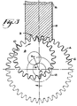
- FIG. 3 shows the position of the work gear 2 at the beginning of the grinding process. The traversal is necessary since, at the position shown in Figure 3, only limited tooth surface contact will occur between the work gear 8 and grinding wheel 2 in this position.
- the work gear 8 meshes with the grinding wheel 2 as the former is traversed in a plane substantially perpendicular to the axis of rotation of the work gear 8.
- the path of traversal is controlled by moving the center of the work gear, X W , in a path about the center, X I , of the theoretical ring gear 6.
- the path taken by the work gear 8 may be circular such as shown by Figure 3 wherein the work gear center, X W , moves about the center, X I , of the theoretical ring gear 6 at a constant radius, R.
- the path of the work gear need not be limited to circular movement.
- Axes 48 (Y-axis) and 72 (X-axis) are arranged perpendicular to each other. It can be seen that the direction of movement of the tool housing 30 and work spindle housing 60 could be reversed, that is, tool housing 30 could move in the X direction and work spindle housing 60 could move in the Y direction. Also, either the tool housing 30 or the work spindle housing 60 could move in both X and Y directions.
- the present inventive grinding process is not limited, as in the prior art plunge-type processes, to decreasing the face width capable of being machined on a work gear as the number of teeth decrease on a work gear.
- the present process also allows a greater portion of the grinding wheel to be utilized during grinding. This is primarily due to the circumferential direction of feeding the work gear into the grinding wheel in contrast to the radial feed direction of the prior art methods.
Landscapes
- Engineering & Computer Science (AREA)
- Mechanical Engineering (AREA)
- Grinding-Machine Dressing And Accessory Apparatuses (AREA)
- Polishing Bodies And Polishing Tools (AREA)
Abstract
Description
- The present invention is directed to a method of machining gears, particularly spur and helical gears, by a generating process utilizing a tool having a generally hourglass shape along the width thereof, a method of dressing a grinding wheel for grinding desired tooth surfaces on spur and helical gears and an apparatus for machining the tooth surfaces of spur and helical gears according to the precharacterising portion of
claims - Machining of spur and helical gears by processes utilizing grinding wheels of the type commonly referred to as globoidal, hyperboloidal or hourglass, has been known in the art for some time.
- A process for producing crowned gear teeth by linearly moving a work gear relative to the concave edge of a grinding wheel having a helical groove is disclosed by US-A-3,110,135 to Berlinsky. In this process, the work gear must be moved at an angle across the edge of the grinding wheel in order to produce straight or convex tooth forms having crowned shapes. The angular movement requires a special mechanism on the grinding machine which inherently complicates the machine and process. Moving the work gear straight across the edge of the grinding wheel produces an unusable concave tooth form and no crowning.
- DE-A-25 16 059 describes a plunge process wherein a hyperboloidal or globoidal grinding worm is utilized for grinding spur and helical gears. The grinding wheel axis and work gear axis are crossed, that is, the projections of the axes into a plane that is parallel to both axes intersect at an angle of less than ninety degrees. This type of axes orientation enables the effective area of the tool to extend from one side face of the work gear to the other so that only a radial change in the distance between the axes is needed for machining. In other words, additional movement of the work gear along its axis to ensure complete machining of the tooth length is not required and the only motion needed is the plunge feed of the grinding wheel relative to the work gear. However, due to stock allowances on the work gear teeth, the tool and work gear surfaces will engage long before the operational center distance is reached. Some portions of the grinding wheel thread will engage the work gear for a longer period of the feed sequence than others and also remove more material. These portions of the grinding wheel will wear faster and cause profile shape problems. Also in this type of "full thread" process, grinding forces would be very high due to the amount of contact between the grinding wheel and the work gear. The process itself is not capable of grinding some gears. The tooth surfaces of the grinding wheel would bind with the work gear before the operational center distance is reached thereby causing operating portions of the gear profiles to be removed.
- The method described by Fragin et al. in "New Method of Finishing Teeth of Hardened Spur Gears",(Vestnik Mashinostroeniya, Volume 55, Issue 7, 1975), sets forth a plunge-type honing process. One flank of each of the work gear teeth is machined by meshing a revolving globoidal abrasive worm with the one flank, the abrasive thread being narrower than the finished tooth gap. The necessary honing force is created by braking the work gear. Simultaneous with the rotation of the grinding worm and work gear, the work gear is given a reciprocating motion along its axis in order that the machining is complete along the entire tooth length. The opposite flank of each of the work gear teeth is machined by reversing the rotation of the grinding worm. Accurate control of the braking force and reciprocating motion is complex and, therefore, constant production of an acceptable gear is difficult.
- Another plunge-type process is disclosed by US-A-4,559,744 to Wirz. In this process a grinding worm is provided with a thread thickness smaller than the finished tooth gap dimension of the work gear. The grinding worm and work gear are rotated at a revolution ratio corresponding to the number of teeth of the grinding worm and work gear. The grinding worm is then fed relative to the work gear until a desired distance is reached between the axes of the grinding worm and work gear with no contact occurring. At this point the threads of the grinding worm are located between adjacent tooth flanks of the work gear teeth. The grinding worm or work gear is then given an additional rotating movement which is superimposed on the basic rotation thereby enabling a first flank of each of the work gear teeth to be machined. The other flank of each of the teeth is machined by providing an additional rotating movement in a direction opposite that provided for machining the first flank.
- A process similar to that of US-A-4,559,744 is described in US-A-4,650,378 to Zubler. In this process, after the tool and work gear are radially moved to the desired center distance, at least one of the tool and work gear are moved in a direction perpendicular to the direction of radial movement in order to machine a first flank of each of the work gear teeth. The other flank of each of the work gear teeth is machined by moving in a direction opposite to the direction required for machining the first flank.
- The latter two processes, like that of Fragin et al. discussed above, are very complex in that control of the additional rotational motion, or, motion in the plane perpendicular to the radial direction, is difficult to accurately implement and monitor. Also, it is known in plunge-type processes that the fewer the number of teeth on a work gear, the smaller the face width capable of being machined. Furthermore, only one size work gear can be machined with each particular grinding wheel tooth form. A change in size of work gear necessitates that the grinding wheel be dressed with a dressing tool having the same size as the desired work gear.
- It is an object of the present invention to provide a method of and machine for machining spur and helical gears wherein the deficiencies of the prior art are eliminated and a wider range of gear sizes are capable of being machined.
- It is another object of the present invention to provide a method and machine wherein a plurality of gear sizes can be machined with a single grinding tool.
- It is yet another object of the present invention to provide an improved method of dressing a grinding tool having a generally hourglass shape along the width thereof.
- These objects are achieved with a method and an apparatus having the features of
claim - The present invention is directed to a machine and process for machining workpieces utilizing a tool having a generally hourglass shape along the width thereof and at least one stock removing surface arranged and spaced along the tool width.
- As in US-A-3 110 135 the present invention is directed to a method and apparatus for grinding spur and helical gears by a generating process utilizing a grinding wheel having an axis of rotation, a width extending in the axial direction of the grinding wheel and a generally hourglass shape along the width. The grinding wheel has at least one stock removing surface generally helically arranged and extending along the width of the grinding wheel. The stock removing surface is conjugate along the width of the grinding wheel with the outer tooth surfaces of a theoretical ring gear.
- The process includes rotating the grinding wheel about its axis which in turn causes a theoretical ring gear to rotate about its axis. A work gear is rotated about its axis and brought into mesh with the internal tooth surfaces of the rotating theoretical ring gear. Simultaneously with rotating in mesh with the theoretical ring gear, the work gear is traversed in mesh relatively across the width of the grinding wheel in a plane substantially perpendicular to the axis of rotation of the work gear. However the present invention enables inter alia usable, non-concave tooth surfaces to be formed on the work gear because it is characterized by the stock removing surface having a continually changing profile shape in a direction along that surface.
- The method of the present invention may be computer controlled and carried out on a machine having a plurality of computer controlled axes for positioning and operatively engaging a tool with a work gear. The method comprises computing rotational speeds and initial positions of the tool and the work gear in response to setup parameters input to the machine whereby the rotation of the tool is synchronized with the rotation of the work gear as though both were rotating in mesh with a rotating theoretical ring gear. Rotating the tool about its axis of rotation and rotating the work gear about its axis of rotation. Moving the computer controlled axes to the initial setup positions for initially positioning the tool and the work gear with respect to each other. Computing further operating positions of the axes in response to operating parameters input to the machine. Moving the computer controlled axes to the further operating positions for operatively engaging the rotating tool and the rotating work gear in a manner as though the tool and work gear were in mesh with the theoretical ring gear rotating about an axis of rotation extending through the center thereof. Moving the computer controlled axes to the further operating positions includes, substantially simultaneously with the rotation, moving the computer controlled axes to traverse the work gear in mesh along a path relatively across the width of the tool in a plane perpendicular to the axis of rotation of the work gear. The steps of computing further operating positions and moving the computer controlled axes to the further operating positions are repeated for completing the machining operation.
- The present process allows a range of work gears to be machined with a single grinding wheel and permits gears having larger face widths to be machined. Another advantage of the present process is that any instant, the area of engagement between the work gear and grinding wheel is relatively small which means that forces acting on the machine are also small. In fact, at any instant, contact between the work gear and grinding wheel is instantaneous point contact (through possibly at two points) which generates less heat and provides better coolant access. The inventive process also allows a greater portion of the width of the grinding wheel to be utilized in the grinding process.
- The present invention also includes a method of dressing a grinding wheel having a generally hourglass shape along the width thereof. The dressing is similar to the grinding process except for minor dimensional changes in the geometry of the dressing tool compared to the geometry of the desired work gear.
- The dressing method of the present invention has the advantages, like those of grinding, of point contact between the dressing tool and grinding wheel whereby forces on the machine are reduced, less heat is generated and coolant access is improved. Also, the dressing tool can be made smaller than the work gear thus reducing the costs of dressing and easing the difficult task of diamond plating the dressing tool since fewer numbers of teeth result in a greater included angle between the sides of a tooth space.
- The present invention will now be discussed with reference to the accompanying drawings which represent the invention by way of example only.
- Figure 1 illustrates a theoretical ring gear in mesh with a grinding wheel having a generally hourglass shape along the width thereof.
- Figure 2 illustrates a work gear in mesh with a theoretical ring gear prior to engagement with a grinding wheel.
- Figure 3 illustrates the position of the work gear relative to the grinding wheel and theoretical ring gear at the beginning of a grinding process embodying the present invention;
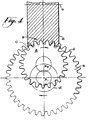
- Figure 4 illustrates the position of the work gear relative to the grinding wheel and theoretical ring gear at about the midpoint of the grinding process;
- Figure 5 illustrates the position of the work gear relative to the grinding wheel and theoretical ring gear near the end of the grinding process;
- Figure 6 schematically illustrates an inventive machine for carrying out the grinding process; and
- Figure 7 schematically illustrates an alternative view of a grinding machine embodying the present invention taken along line A-A of Figure 6.
- Figure 1 illustrates a stock removing tool such as a grinding wheel 2 having an axis of
rotation 5 and a width extending in the axial direction of the grinding wheel. The grinding wheel 2 comprises a generally hourglass shape along its width and is made of a suitable abrasive material such as aluminum oxide or cubic boron nitride (CBN). Although the present specification discusses the invention with references to grinding, it is to be understood that the principles of the present invention are also applicable to other types of stock removal, such as cutting or honing, utilizing a tool having a generally hourglass shape along its width. The grinding wheel 2 has a diameter and at least onestock removing surface 3 generally helically arranged around the periphery thereof and extending along its width. The grinding wheel 2 is conjugate along its entire width with theouter tooth surfaces 4 of atheoretical ring gear 6 having an axis of rotation passing through its center, XI. Since thetheoretical ring gear 6 is conjugate along the entire width of the grinding wheel 2 it therefore represents the largest diameter gear that can mesh with the grinding wheel 2. - In Figure 2 a
work gear 8 having an axis of rotation passing through its center, XW, is shown at a position relative to the grinding wheel 2 just prior to its engagement with the grinding wheel 2. Theaxis 5 of the grinding wheel 2 and the axis XW of thework gear 8 are oriented in a what is known as a crossed-axis arrangement wherein the angle between theaxes 5 and XW, known as the machine helix angle, is less than ninety degrees. The amount less than ninety degrees is dependent primarily upon the helix angle of thework gear 8 and the helix angle of the stock removing surface on the grinding wheel 2. In the position shown in Figure 2 there is no contact between thework gear 8 and grinding wheel 2 even though the center line of thetheoretical gear 6 is at the manufacturing center distance relative to the grinding wheel axis. An advantage of the present process is that any work gear having a diameter smaller than thetheoretical ring gear 6 and capable of meshing with the internal tooth surfaces 10 of thetheoretical ring gear 6 can be machined by the process of the present invention. The grinding wheel 2 is rotated at a desired speed which in turn causes thetheoretical ring gear 6 to rotate at a speed dependent upon the rotational speed of the grinding wheel 2. Thework gear 8 is then rotated and positioned as though it were in mesh with the rotatingtheoretical ring gear 6. Thus, thetheoretical ring gear 6 is in mesh with both thework gear 8 and the grinding wheel 2. Since the diameter of thework gear 8 is smaller than that of thetheoretical ring gear 6, the rotational speed of thework gear 8 will necessarily be greater than the speed of thetheoretical ring gear 6. It is to be noted that although the rotations of thetheoretical ring gear 6 and thework gear 8 are shown to be in a clockwise direction, the present invention is not limited to a particular direction of rotation. A particular direction of rotation is shown for reference purposes only. - Once in mesh with the rotating
theoretical ring gear 6, therotating work gear 8, substantially simultaneously with its rotation, is traversed relatively across the width of the grinding wheel 2. Figure 3 shows the position of the work gear 2 at the beginning of the grinding process. The traversal is necessary since, at the position shown in Figure 3, only limited tooth surface contact will occur between thework gear 8 and grinding wheel 2 in this position. Thework gear 8 meshes with the grinding wheel 2 as the former is traversed in a plane substantially perpendicular to the axis of rotation of thework gear 8. The path of traversal is controlled by moving the center of the work gear, XW, in a path about the center, XI, of thetheoretical ring gear 6. The path taken by thework gear 8 may be circular such as shown by Figure 3 wherein the work gear center, XW, moves about the center, XI, of thetheoretical ring gear 6 at a constant radius, R. However, the path of the work gear need not be limited to circular movement. - Figures 4 and 5 show, respectively, the positions of the
work gear 8 as it is traversed relatively across the width of the grinding wheel 2 at about the midpoint of the grinding process and near the completion of the grinding process. In the course of moving in this manner, the tooth surfaces of thework gear 8 are brought into conjugacy with the portions of thetheoretical ring gear 6 that engage the grinding wheel 2. The machining action that would otherwise be done on thetheoretical ring gear 6 is done instead on thework gear 8. Once thework gear 8 has traversed the width of the grinding wheel 2 the process is complete, all tooth surfaces have been machined. The inventive process has the advantage in that, at any instant, the area of engagement between thework gear 8 and grinding wheel 2 is relatively small. This means that the forces acting on the machine system are also small. - The rotation of the
work gear 8 and the movement of its center, XW, about the center, XI, of thetheoretical ring gear 6 may be accomplished by mechanical means. This mechanical arrangement, however, permits the machine system to produce only a single gear specification. A preferred embodiment is to utilize a pair of computer numerically controlled (CNC) slides that can move the center of a work gear along any circular or noncircular path about the center of a theoretical ring gear. A given grinding wheel shape can be used to grind a range of gears each of which is smaller than the theoretical ring gear and internally conjugate with the theoretical ring gear. For each work gear, the center, XW, is moved along an appropriate path while at the same time the work gear is rotated as if engaged with the theoretical ring gear. The CNC approach has the added advantage that tooth surface modifications can be introduced by varying the shape of the path along which the work gear center, XW, moves and/or varying the rotation of the work gear relative to the grinding wheel. - An apparatus for carrying out the inventive process is schematically shown by Figure 6.
Apparatus 20 comprises amachine base 22,tool housing 30 andwork spindle housing 60.Tool housing 30 includes hourglass-shaped grinding wheel 2 mounted to aspindle 32 and rotatable about grindingwheel axis 5. Wheel spindle drivemotor 36 is connected to thegrinding wheel spindle 32 by a series of wheel spindle drive gears 38, 40 and 42. Grinding wheel 2 and its associated drive components, namelyspindle 32, drivemotor 36 and drive gears 38, 40 and 42 are contained in arotatable drum 44.Drum 44 is rotated by aservo motor 46 for setting the desired machine helix angle required for the particular gear being machined.Tool housing 30 is linearly movable by way of slides (not shown) along axis 48 (Y-axis) parallel tomachine base 22 by aservo motor 50 connected totool housing 30 by asuitable arrangement 52 such as a ball screw. -
Work spindle housing 60 comprises a work holding means 62, such as an arbor, for mountingwork gear 8 such that it is rotatable about its axis ofrotation 14. Work holding means 62 is connected to workspindle 64 which is in turn connected, byappropriate means 68, to work spindle servo motor 70 for rotating thework gear 8.Work spindle housing 60 is also linearly movable, by way of slides, parallel tomachine base 22 along axis 72 (X-axis) byservo motor 74 connected to workspindle housing 60 by a suitable arrangement such as a ball screw. - Axes 48 (Y-axis) and 72 (X-axis) are arranged perpendicular to each other. It can be seen that the direction of movement of the
tool housing 30 andwork spindle housing 60 could be reversed, that is,tool housing 30 could move in the X direction and workspindle housing 60 could move in the Y direction. Also, either thetool housing 30 or thework spindle housing 60 could move in both X and Y directions. - Figure 7 illustrates an alternative view of the present inventive apparatus taken along line 7-7 of Figure 6. It can be seen that the grinding wheel 2 has been set at a desired machine helix angle 82 for
machining work gear 8. The machine helix angle 82 being the angle between thegrinding wheel axis 5 and theplane 80 perpendicular to the axis ofrotation 14 ofwork gear 8. The traversal ofwork gear 8 across the width of grinding wheel 2 takes place within theplane 80. - Each of the respective drive motors, 36, 46, 50, 70 and 74 is associated with either a linear or rotary encoder (not shown) as part of a CNC system which governs the operation of the drive motors in accordance with instructions input to a computer (not shown). The encoders provide feedback information to the computer concerning the actual positions of each of the movable machine axes.
- In operation, the
work spindle housing 60 is moved back along theX-axis 72 to a retracted position for loading and unloading thework gear 8. Thework gear 8 may be loaded and unloaded manually or automatically. After thework gear 8 is mounted on the work holding means 62 and clamped by movement of thetailstock 78, thework spindle 64 is brought into the required rotational synchronization with the rotation of the grinding wheel 2. Also, by some external means, thework gear 8 is brought to a rotational location such that the teeth of thework gear 8 will centrally engage the spaces between the threads of the grinding wheel 2. This location procedure is known as stock dividing and is well known in the art. Thetool housing 30 and thework spindle housing 60 are brought to a position whereby the axis of thework gear 8 is at the beginning of thepath 12 that thework gear axis 14 must follow relative to the center, XI, of thetheoretical ring gear 6. See Figure 2. The X and Y axes, 72 and 48, then move in concert to carry thework gear 8 through the zone of engagement relative to the grinding wheel 2. Both sides of the work gear teeth are machined during this engagement. The work spindlehousing 60 then retracts to the load/unload position. Thetool housing 30 may move to some convenient position in preparation for the next grinding cycle. - The grinding wheel 2 of the present invention may be dressed by a dressing tool having essentially the same specifications as the desired
work gear 8. The dressing tool differs only in the addendum and dedendum dimensions. The dressing tool may have the same number of teeth as the work gear or it may have fewer or greater numbers of teeth. However many teeth, the dressing tool must be capable of meshing with the internal tooth surfaces of the theoretical ring gear. Regardless of the number of teeth, the specifications must be essentially the same as the work gear, that is, the module, pressure angle and helix angle of the dressing tool must be the same as the work gear. The addendum is somewhat longer in order that the root portions of the grinding wheel 2 are cut deep enough in dressing that during subsequent grinding, the root portions of the grinding wheel do not contact the toplands of the work gear. The dedendum is formed somewhat shorter in order that the root portions of the dressing tool remove stock from the toplands of the grinding wheel thread such that during subsequent grinding, the toplands of the threads of the grinding wheel do not grind the root portions of the work gear. - The dressing process is carried out in the same manner as the grinding process with the dressing tool rotating about its axis and traversing across the width of the grinding wheel 2 in a plane perpendicular to the axis of the dressing tool as though both were engaged with the
theoretical ring gear 6. The path followed by the center of the dressing tool may also be CNC controlled. Tooth surface variations on the work gear may be introduced by varying, during machining, from the circular path of the center of the work gear moving about the center of the theoretical ring gear. Tooth surface variations on the work gear may also be introduced by varying, during dressing, from the circular path of the center of the dressing tool moving about the center of the theoretical ring gear. The latter approach results in the particular variation being included directly on the grinding surface which is subsequently formed on the work gear without the need for moving the work gear along a path other than the circular path. - The surface that is dressed onto the thread or threads of the grinding wheel 2 is such that the profile of the thread or threads is continually changing along the width of the grinding wheel 2. That is, the thread profile as seen in any axial cross-section is unique. As the dressing tool rotates and traverses across the grinding wheel 2, there is point-to-point contact between the teeth of the dressing tool and the threads of the grinding wheel which, at any instant, are at different and unique contact positions as the dressing tool rotates and traverses across the grinding wheel 2. This type of contact generates a continually changing profile surface on the threads in a direction along the helically arranged stock removing surface of the grinding wheel 2. When the dressed grinding wheel contacts a rotating and traversing work gear, the surface dressed onto the grinding wheel produces a surface on the teeth of the work gear that is conjugate to the internal surface on the theoretical ring gear. The contact between the grinding wheel and the work gear is also point-to-point contact. This type of contact, when compared to the line contact of the prior art, results in a smaller grinding area that generates less heat and provides better coolant access.
- After each dressing operation there is a slight change in the helix angle of the grinding wheel. Therefore, the angle between the work gear and grinding wheel must be accordingly adjusted to account for this change in the grinding wheel helix angle. This adjustment is accomplished by rotatably adjusting
drum 44 thereby adjusting the machine helix angle. - The dressing method of the present invention has the advantage that the cost of the dressing tool can be reduced. The dressing tool can be made smaller than the workpiece and, therefore, there are fewer teeth that require diamond plating and corrective grinding. It is easier to diamond plate the tooth surfaces of a gear with a small number of teeth than a gear with a large number. This is due to the greater included angle between the sides of a tooth space. In the prior art, where the dressing tool is the same size and has the same number of teeth as the work gear, it is extremely difficult to achieve adequate diamond grain deposition on the lower flanks of the dressing tools. It is especially difficult on gears with low pressure angles.
- Another advantage to the dressing process of the present invention is that dressing forces are significantly reduced because of the smaller area of engagement between the dressing tool and the grinding wheel. The rigidity between the two will therefore be increased and the errors caused by deflections will be reduced.
- The present inventive grinding process is not limited, as in the prior art plunge-type processes, to decreasing the face width capable of being machined on a work gear as the number of teeth decrease on a work gear. The present process also allows a greater portion of the grinding wheel to be utilized during grinding. This is primarily due to the circumferential direction of feeding the work gear into the grinding wheel in contrast to the radial feed direction of the prior art methods.
Claims (17)
- A method of machining spur and helical gears, said method comprising:providing a stock removing tool (2) having an axis of rotation (5), a width extending in the axial direction of said stock removing tool and a diameter, said stack removing tool (2) being of a generally hourglass shape along said width and having at least one stock removing surface (3) generally helically arranged about the axis and extending along said width, of said stock removing tool, said at least one stock removing surface being conjugate along the entirety of said width with the tooth surfaces (4) of a theoretical ring gear (6),rotating a work gear (8) having an axis of rotation (Xw) and having a diameter less than the diameter of said theoretical ring gear about its axis of rotation,rotating said stock removing tool (2) about its axis of rotation, said theoretical ring gear (6) rotating in mesh with said stock removing tool,traversing said rotating work gear (8) relatively across said width of said stock removing tool, said traversing comprising rotating said work gear at a speed whereby it meshes with the internal tooth surfaces of said rotating theoretical ring gear and simultaneously moving said work gear along a path about the center (X1)of said theoretical ring gear whereby said work gear traverses in mesh with said at least one stock removing surface relatively across said width of said stock removing tool,
characterized in that said stock removing surface has a continually changing profile shape in a direction along said generally helically arranged stock removing surface. - The method of claim 1 wherein said path about said center of said theoretical ring gear is a substantially circular path.
- The method of claim 1 wherein said at least one thread-like stock removing surface simultaneously removes stock material from opposite sides of adjacent teeth of said work gear.
- The method of claim 1 wherein said stock removing tool is a grinding wheel.
- The method of claim 1 wherein the machined gears comprise non-concave longitudinal tooth curvature.
- A method of dressing a grinding wheel (2) for grinding desired tooth surfaces on spur and helical gears, said grinding wheel having an axis of rotation, a width extending in the axial direction of said grinding wheel and a diameter, said grinding wheel having a generally hourglass shape along said width with at least one grinding surface generally helically arranged and extending along said width of said grinding wheel, said method comprising the steps of:providing a dressing tool having an axis of rotation and a plurality of tooth surfaces, said dressing tool having essentially the same specifications as a desired work gear (8) and comprising a coating of hard abrasive material on said tooth surfaces,rotating said dressing tool about its axis of rotation,rotating said grinding wheel (2) about its axis of rotation, said theoretical ring gear rotating in mesh with said grinding wheel,traversing said rotating dressing tool relatively across said width of said grinding wheel in a plane substantially perpendicular to said axis of rotation of said dressing tool, said traversing comprising rotating said dressing tool at a speed whereby it meshes with the internal tooth surfaces of said rotating theoretical ring gear and simultaneously moving said dressing tool along a path about the center of said theoretical ring gear whereby said dressing tool traverses in mesh with said at least one grinding surface relatively across said width of said grinding wheel,
characterized in that the grinding surface has a continually changing profile shape in the direction along said generally helically arranged stock removing surface. - The method of claim 6 wherein said dressing tool comprises the same specifications as said desired work gear with the exception that said dressing tool includes a smaller dedendum dimension and a larger addendum dimension than said desired work gear.
- The method of claim 6 wherein said path about said center of said theoretical ring gear is a substantially circular path.
- The method of claim 6 wherein said dressing tool comprises a different number of teeth than said desired work gear.
- The method of claim 9 wherein said dressing tool comprises fewer teeth than said desired work gear.
- An apparatus (20) for machining the tooth surfaces of spur and helical gears, said apparatus comprising:a machine base (2),a tool housing (30) located on said machine base, said tool housing comprising a stock removing tool (2) rotatable about an axis (5), said stock removing tool having width extending in the axial direction thereof, said stock removing tool having generally hourglass shape along said width and comprising at least one stock removing surface (3) generally helically arranged and extending along said width of said stock removing tool, said stock removing tool being releasably secured in a rotatable drum (44) in said tool housing, said rotatable drum being rotatably adjustable for setting the machine helix angle of said stock removing tool,a work spindle housing (60) located on said machine base (22), said work spindle housing comprising work holding means (62) for rotatably mounting at least one workpiece thereon for rotation about its axis of rotation,means (50,52;74) for simultaneously moving said tool housing and said work spindle housing relative to one another in mutually perpendicular directions (X,Y) whereby said at least one workpiece is traversed along a predetermined path relatively across said generally hourglass shape of said stock removing tool in a plane substantially perpendicular to the axis of rotation of said at least one workpiece,
characterized in that the stock removing surface has a continually changing profile shape in the direction along said generally helical arranged stock removed surface. - The apparatus of claim 11 wherein said path is a circular path.
- The apparatus of claim 11 wherein at least said means for simultaneously moving are computer numerically controlled.
- The apparatus of claim 13 further including the rotations of said stock removing tool, said at least one workpiece and said drum being computer numerically controlled.
- The apparatus of claim 11 wherein said means for simultaneously moving comprise slides and ball screws (52).
- The apparatus of claim 11 wherein said tool housing (30) is movable in one of said perpendicular directions and said work spindle housing (60) is movable in the other of said perpendicular directions.
- The apparatus of claim 11 wherein one of said tool housing (30) and said work spindle housing (60) is movable in both of said perpendicular directions.
Applications Claiming Priority (3)
| Application Number | Priority Date | Filing Date | Title |
|---|---|---|---|
| US07/755,400 US5175962A (en) | 1991-09-05 | 1991-09-05 | Method of and apparatus for machining spur and helical gears |
| US755400 | 1991-09-05 | ||
| PCT/US1991/009753 WO1993004810A1 (en) | 1991-09-05 | 1991-12-23 | Method of and apparatus for machining spur and helical gears |
Publications (2)
| Publication Number | Publication Date |
|---|---|
| EP0602038A1 EP0602038A1 (en) | 1994-06-22 |
| EP0602038B1 true EP0602038B1 (en) | 1997-10-01 |
Family
ID=25038981
Family Applications (1)
| Application Number | Title | Priority Date | Filing Date |
|---|---|---|---|
| EP92906389A Expired - Lifetime EP0602038B1 (en) | 1991-09-05 | 1991-12-23 | Method of and apparatus for machining spur and helical gears |
Country Status (8)
| Country | Link |
|---|---|
| US (1) | US5175962A (en) |
| EP (1) | EP0602038B1 (en) |
| JP (1) | JPH06510242A (en) |
| KR (1) | KR0145455B1 (en) |
| AU (1) | AU1375792A (en) |
| CA (1) | CA2117072C (en) |
| DE (1) | DE69127833T2 (en) |
| WO (1) | WO1993004810A1 (en) |
Families Citing this family (31)
| Publication number | Priority date | Publication date | Assignee | Title |
|---|---|---|---|---|
| US5289815A (en) * | 1993-06-21 | 1994-03-01 | The Gleason Works | Method of dressing a threaded grinding wheel |
| US5573449A (en) * | 1994-03-16 | 1996-11-12 | The Gleason Works | Threaded grinding wheel, method of dressing, and grinding a workpiece therewith |
| CN1093948C (en) * | 1996-03-29 | 2002-11-06 | 格里森工场 | Method of evaluating workpiece for machining |
| US6146253A (en) * | 1996-04-23 | 2000-11-14 | Mcdonnell Douglas Helicopter Company | Apparatus and method for precision grinding face gear |
| US6390894B1 (en) * | 1998-12-21 | 2002-05-21 | Derlan Aerospace Canada | Face gear manufacturing method and apparatus |
| US6450740B1 (en) * | 2000-04-24 | 2002-09-17 | Deere & Company | Mechanical gear hob with stock divide by differential gear box |
| JP3517403B2 (en) * | 2000-06-23 | 2004-04-12 | ヤマザキマザック株式会社 | Multi-task machine tools |
| DE10220513B4 (en) * | 2002-05-08 | 2004-04-15 | Gleason-Pfauter Maschinenfabrik Gmbh | Process for dressing or profiling a cylindrical or essentially cylindrical grinding worm |
| US6916140B2 (en) * | 2003-09-24 | 2005-07-12 | Yakov Fleytman | Method of producing an enveloping worm |
| JP4959982B2 (en) * | 2003-10-17 | 2012-06-27 | トリナリー・アンラーゲンバウ・ゲゼルシャフト・ミット・ベシュレンクテル・ハフツング | Multi-axis machine tool for manufacturing a workpiece having a screw-shaped generating surface, method for starting multi-axis machine tool, recording medium storing data to be read into multi-axis machine tool, for multi-axis machine tool Method for creating machine control parameters, computer system for creating machine control parameters for a multi-axis machine tool, and computer program for creating machine control parameters |
| JP4714582B2 (en) * | 2003-10-17 | 2011-06-29 | トリナリー・アンラーゲンバウ・ゲゼルシャフト・ミット・ベシュレンクテル・ハフツング | Method for preventing machine tool misstart |
| ATE389505T1 (en) * | 2004-03-01 | 2008-04-15 | Wolfgang Linnenbrink | PROCESS AND APPARATUS FOR SMOOTHING GEARS |
| DE102004057596B4 (en) | 2004-04-22 | 2009-06-04 | Reishauer Ag | Profiling gear and method for profiling a grinding worm |
| KR100841748B1 (en) * | 2005-09-09 | 2008-06-27 | 주식회사 해성산전 | Grinder Apparatus for Cycloid Gear |
| JP4648219B2 (en) * | 2006-02-28 | 2011-03-09 | 三菱重工業株式会社 | Gear grinding machine |
| US8277285B2 (en) * | 2006-05-24 | 2012-10-02 | The Gleason Works | Method of maintaining a constant grinding process |
| US7540821B2 (en) * | 2006-10-27 | 2009-06-02 | Torvec, Inc | Full traction differential with hybrid gearing |
| USRE44158E1 (en) * | 2006-10-27 | 2013-04-16 | Torvec, Inc. | Full traction differential with hybrid gearing |
| US7465220B1 (en) * | 2007-09-27 | 2008-12-16 | Wolff Industries, Inc. | Apparatus and method for corrugating resharpened blades |
| JP5285416B2 (en) * | 2008-12-22 | 2013-09-11 | 三菱重工業株式会社 | Internal gear grinding machine and barrel threading tool dressing method |
| JP5285526B2 (en) * | 2009-07-27 | 2013-09-11 | 三菱重工業株式会社 | Internal gear machining method and tool dressing method used therefor |
| RU2542040C2 (en) * | 2009-08-03 | 2015-02-20 | Те Глисон Воркс | Method and tool for making of flat gear wheels |
| EP2528705B1 (en) * | 2010-01-29 | 2013-10-23 | The Gleason Works | Continuous method for manufacturing face gears |
| DE102010023728A1 (en) * | 2010-06-14 | 2011-12-15 | Liebherr-Verzahntechnik Gmbh | Method of manufacturing a plurality of identical gears by means of machining |
| CN101941102B (en) * | 2010-08-27 | 2012-01-11 | 西安理工大学 | Displacement analog loading device of form grinding wheel gear grinding machine and method for detecting rigidity distribution |
| JP5705567B2 (en) * | 2011-01-31 | 2015-04-22 | 三菱重工業株式会社 | Gear grinding method |
| JP5854792B2 (en) * | 2011-11-25 | 2016-02-09 | 三菱重工業株式会社 | Dressing method for hourglass gear wheel and disk-shaped dresser |
| EP2774721B1 (en) * | 2013-03-05 | 2015-11-04 | Klingelnberg AG | Method for determining topographical deviations of a dressing tool in a grinding machine, and grinding machine provided with same |
| CH709478A1 (en) * | 2014-04-08 | 2015-10-15 | Reishauer Ag | Methods and apparatus for fast and flexible dressing of the grinding worm. |
| CN105081479B (en) * | 2015-09-08 | 2016-08-24 | 盐城秦川华兴机床有限公司 | A kind of efficient numerically controlled gear grinding machines realizing many point grinding and automatic centering |
| CN108580928B (en) * | 2018-04-28 | 2020-03-10 | 重庆润跃机械有限公司 | Turning device for gear |
Family Cites Families (13)
| Publication number | Priority date | Publication date | Assignee | Title |
|---|---|---|---|---|
| US1759333A (en) * | 1927-07-20 | 1930-05-20 | Wildhaber Ernest | Method of forming gears |
| CH373624A (en) * | 1961-04-07 | 1963-05-31 | Borer Hugo | Method and device for polishing gears and pinions for watches |
| US3110135A (en) * | 1961-11-06 | 1963-11-12 | Holtzer Cabot Corp | Gear cutting apparatus |
| DE2516059B2 (en) * | 1975-04-12 | 1980-08-28 | Carl Hurth Maschinen- Und Zahnradfabrik, 8000 Muenchen | Tool for manufacturing or machining spur gears |
| US4037365A (en) * | 1976-06-25 | 1977-07-26 | Caterpillar Tractor Co. | Apparatus for cutting arcuately-shaped worms |
| CH650183A5 (en) * | 1981-01-27 | 1985-07-15 | Reishauer Ag | METHOD FOR MACHINING A GEAR WITH A ROTATING TOOL. |
| JPS60114423A (en) * | 1983-08-09 | 1985-06-20 | Honda Motor Co Ltd | Mating device |
| DE3345800C2 (en) * | 1983-12-17 | 1986-09-11 | Carl Hurth Maschinen- und Zahnradfabrik GmbH & Co, 8000 München | Device for manufacturing and processing gears |
| CH664716A5 (en) * | 1984-02-10 | 1988-03-31 | Reishauer Ag | METHOD AND DEVICE FOR MACHINING THE TOOTHED FLANGES OF A ROTATING, TOOTHED WORKPIECE. |
| CH676099A5 (en) * | 1984-09-05 | 1990-12-14 | Reishauer Ag | |
| WO1989001838A1 (en) * | 1987-08-24 | 1989-03-09 | The Gleason Works | Multi-axis bevel and hypoid gear generating machine |
| DE8910726U1 (en) * | 1989-09-08 | 1991-01-10 | Carl Hurth Maschinen- und Zahnradfabrik GmbH & Co, 8000 München | Machine for fine machining of tooth flanks of toothed workpieces |
| US5044127A (en) * | 1990-01-16 | 1991-09-03 | The Gleason Works | Gear-shaped tool and method of generating gears |
-
1991
- 1991-09-05 US US07/755,400 patent/US5175962A/en not_active Expired - Fee Related
- 1991-12-23 DE DE69127833T patent/DE69127833T2/en not_active Expired - Fee Related
- 1991-12-23 KR KR1019940700310A patent/KR0145455B1/en not_active IP Right Cessation
- 1991-12-23 WO PCT/US1991/009753 patent/WO1993004810A1/en active IP Right Grant
- 1991-12-23 JP JP4505675A patent/JPH06510242A/en active Pending
- 1991-12-23 EP EP92906389A patent/EP0602038B1/en not_active Expired - Lifetime
- 1991-12-23 AU AU13757/92A patent/AU1375792A/en not_active Abandoned
- 1991-12-23 CA CA002117072A patent/CA2117072C/en not_active Expired - Fee Related
Also Published As
| Publication number | Publication date |
|---|---|
| WO1993004810A1 (en) | 1993-03-18 |
| CA2117072A1 (en) | 1993-03-18 |
| US5175962A (en) | 1993-01-05 |
| KR0145455B1 (en) | 1998-07-01 |
| DE69127833T2 (en) | 1998-05-07 |
| JPH06510242A (en) | 1994-11-17 |
| CA2117072C (en) | 1996-10-08 |
| DE69127833D1 (en) | 1997-11-06 |
| AU1375792A (en) | 1993-04-05 |
| EP0602038A1 (en) | 1994-06-22 |
Similar Documents
| Publication | Publication Date | Title |
|---|---|---|
| EP0602038B1 (en) | Method of and apparatus for machining spur and helical gears | |
| US4635404A (en) | Apparatus for machining a spur gear by means of a rotating gearlike tool | |
| KR100291167B1 (en) | Method of machining gears during indexing | |
| JP2550038B2 (en) | Method for grinding teeth of a bevel gear pair with helical teeth and apparatus for carrying out this method | |
| US5857896A (en) | Method and device for the fine machining of spur or helical gear wheels | |
| US6234880B1 (en) | Device and method for profiling grinding worms | |
| KR100865053B1 (en) | Gear grinding machine, method for dressing threaded grinding wheel and method for grinding work | |
| EP0750538B1 (en) | Threaded grinding wheel, method of dressing, and grinding a workpiece therewith | |
| US7972197B2 (en) | Grinding machine for grinding of a gear | |
| JP3136409B2 (en) | Method and mechanism for polishing the exterior side of a channel on a work piece | |
| JPH1058292A (en) | Contour forming method for continuous roller grinding worm and tool and device for use in it | |
| KR20100069587A (en) | Dressing gear and method for dressing a gear-shaped grinding wheel | |
| US6497610B1 (en) | Process for dressing an internal or external gear tool for fine machining of tooth profiles | |
| US4650378A (en) | Method for machining a gear by means of a rotating gear-type tool | |
| CN114619103A (en) | Gear machining method and gear machining device | |
| US20040005843A1 (en) | Method for dressing or profiling of an essentially cylindrical grinding worm | |
| US20090060672A1 (en) | Multiple Operation Gear Manufacturing Apparatus With Common Work Axis | |
| JP3800360B2 (en) | Processing method of involute tooth profile | |
| CN115194259A (en) | Method for producing a torsion on the tooth surface of an internally toothed workpiece | |
| JPH09168923A (en) | Gear having circumferential partial teeth, grinding wheel for the gear, and grinding method and device for the gear | |
| JP3612726B2 (en) | On-machine forming method of internal gear type honing wheel in gear honing machine | |
| JPH09174331A (en) | Method and device for gear meshing of internal gear grinding wheel of hard gear honing panel | |
| JPH0732214A (en) | Dressing gear | |
| US3090168A (en) | Tool head for finishing machine | |
| JPS62228320A (en) | Finishing method for tooth surface of gear |
Legal Events
| Date | Code | Title | Description |
|---|---|---|---|
| PUAI | Public reference made under article 153(3) epc to a published international application that has entered the european phase |
Free format text: ORIGINAL CODE: 0009012 |
|
| 17P | Request for examination filed |
Effective date: 19940325 |
|
| AK | Designated contracting states |
Kind code of ref document: A1 Designated state(s): DE FR GB IT SE |
|
| 17Q | First examination report despatched |
Effective date: 19950619 |
|
| GRAG | Despatch of communication of intention to grant |
Free format text: ORIGINAL CODE: EPIDOS AGRA |
|
| GRAH | Despatch of communication of intention to grant a patent |
Free format text: ORIGINAL CODE: EPIDOS IGRA |
|
| GRAH | Despatch of communication of intention to grant a patent |
Free format text: ORIGINAL CODE: EPIDOS IGRA |
|
| GRAA | (expected) grant |
Free format text: ORIGINAL CODE: 0009210 |
|
| AK | Designated contracting states |
Kind code of ref document: B1 Designated state(s): DE FR GB IT SE |
|
| REF | Corresponds to: |
Ref document number: 69127833 Country of ref document: DE Date of ref document: 19971106 |
|
| ET | Fr: translation filed | ||
| ITF | It: translation for a ep patent filed | ||
| PLBE | No opposition filed within time limit |
Free format text: ORIGINAL CODE: 0009261 |
|
| STAA | Information on the status of an ep patent application or granted ep patent |
Free format text: STATUS: NO OPPOSITION FILED WITHIN TIME LIMIT |
|
| 26N | No opposition filed | ||
| PGFP | Annual fee paid to national office [announced via postgrant information from national office to epo] |
Ref country code: SE Payment date: 20001201 Year of fee payment: 10 |
|
| PGFP | Annual fee paid to national office [announced via postgrant information from national office to epo] |
Ref country code: FR Payment date: 20011203 Year of fee payment: 11 |
|
| PG25 | Lapsed in a contracting state [announced via postgrant information from national office to epo] |
Ref country code: SE Free format text: LAPSE BECAUSE OF NON-PAYMENT OF DUE FEES Effective date: 20011224 |
|
| REG | Reference to a national code |
Ref country code: GB Ref legal event code: IF02 |
|
| EUG | Se: european patent has lapsed |
Ref document number: 92906389.9 |
|
| PGFP | Annual fee paid to national office [announced via postgrant information from national office to epo] |
Ref country code: GB Payment date: 20021104 Year of fee payment: 12 |
|
| PGFP | Annual fee paid to national office [announced via postgrant information from national office to epo] |
Ref country code: DE Payment date: 20021230 Year of fee payment: 12 |
|
| PG25 | Lapsed in a contracting state [announced via postgrant information from national office to epo] |
Ref country code: FR Free format text: LAPSE BECAUSE OF NON-PAYMENT OF DUE FEES Effective date: 20030901 |
|
| REG | Reference to a national code |
Ref country code: FR Ref legal event code: ST |
|
| PG25 | Lapsed in a contracting state [announced via postgrant information from national office to epo] |
Ref country code: GB Free format text: LAPSE BECAUSE OF NON-PAYMENT OF DUE FEES Effective date: 20031223 |
|
| PG25 | Lapsed in a contracting state [announced via postgrant information from national office to epo] |
Ref country code: DE Free format text: LAPSE BECAUSE OF NON-PAYMENT OF DUE FEES Effective date: 20040701 |
|
| GBPC | Gb: european patent ceased through non-payment of renewal fee |
Effective date: 20031223 |
|
| PG25 | Lapsed in a contracting state [announced via postgrant information from national office to epo] |
Ref country code: IT Free format text: LAPSE BECAUSE OF NON-PAYMENT OF DUE FEES;WARNING: LAPSES OF ITALIAN PATENTS WITH EFFECTIVE DATE BEFORE 2007 MAY HAVE OCCURRED AT ANY TIME BEFORE 2007. THE CORRECT EFFECTIVE DATE MAY BE DIFFERENT FROM THE ONE RECORDED. Effective date: 20051223 |