EP0601408A2 - Outil pour sertir des embouts isolés en bande sur des extrémités de fils - Google Patents
Outil pour sertir des embouts isolés en bande sur des extrémités de fils Download PDFInfo
- Publication number
- EP0601408A2 EP0601408A2 EP93119036A EP93119036A EP0601408A2 EP 0601408 A2 EP0601408 A2 EP 0601408A2 EP 93119036 A EP93119036 A EP 93119036A EP 93119036 A EP93119036 A EP 93119036A EP 0601408 A2 EP0601408 A2 EP 0601408A2
- Authority
- EP
- European Patent Office
- Prior art keywords
- drive
- wire end
- crimping
- tool according
- station
- Prior art date
- Legal status (The legal status is an assumption and is not a legal conclusion. Google has not performed a legal analysis and makes no representation as to the accuracy of the status listed.)
- Withdrawn
Links
Images


Classifications
-
- H—ELECTRICITY
- H01—ELECTRIC ELEMENTS
- H01R—ELECTRICALLY-CONDUCTIVE CONNECTIONS; STRUCTURAL ASSOCIATIONS OF A PLURALITY OF MUTUALLY-INSULATED ELECTRICAL CONNECTING ELEMENTS; COUPLING DEVICES; CURRENT COLLECTORS
- H01R43/00—Apparatus or processes specially adapted for manufacturing, assembling, maintaining, or repairing of line connectors or current collectors or for joining electric conductors
- H01R43/04—Apparatus or processes specially adapted for manufacturing, assembling, maintaining, or repairing of line connectors or current collectors or for joining electric conductors for forming connections by deformation, e.g. crimping tool
- H01R43/042—Hand tools for crimping
- H01R43/045—Hand tools for crimping with contact member feeding mechanism
Definitions
- the invention relates to a tool for pressing insulated wire end sleeves in tape form, with a charging station for inserting a stripped conductor end into a wire end sleeve provided with a plastic collar, a crimping station having two press jaws and with a transport device for feeding from the charging station into the crimping station, the tool being connectable to a drive having a forward stroke and a reverse stroke.
- the tool in question is connected to or is equipped with a drive.
- Wire end sleeves are processed in tape form, that is to say wire end sleeves which are connected to one another in a tape-like manner via coherent areas within the plastic collar.
- such tapes of wire end sleeves are processed in which the plastic collars are injection molded attached to each other without a substantial distance, so that no waste occurs when each wire end sleeve is separated from the tape.
- a tool of the type described at the beginning is known in the form of pliers, two hand levers being provided as the drive.
- the tool is designed as a combination tool and allows the conductor to be cut off in a separate station, the conductor end stripped in another station and finally crimped in a crimping station.
- the wire end sleeves are not transported in tape form during cutting and stripping.
- the conductor is first inserted into the charging station with its stripped conductor end through the collar-side end of the wire end sleeve and pushed under pressure onto the conductor so that the front end of the wire end sleeve is inserted into a transport wheel disc, through which Rotation the parts are transported from the charging station to the crimping station.
- the crimping is then carried out by moving two press jaws relative to one another will.
- the disadvantage of this is that the transport of the parts from the loading station into the crimping station is dependent on a coupling process to be carried out by hand and only takes place when the transport wheel disc is also properly reached.
- the pressure to be exerted by hand ensures that the stripped end of the conductor is properly seated in the ferrule, but there is a risk with thin or soft conductors that the conductor can bend.
- Another major disadvantage is that only a certain area of the ferrule can be gripped with the crimping process.
- a pair of pliers for pressing wire end sleeves in band form is also known, in which the strip of wire end sleeves is inserted into a magazine.
- the magazine loaded in this way is inserted into the pliers.
- the magazine has a recess through which the band of the ferrules can be grasped with the thumb of the hand and pushed forward by a division until the foremost ferrule lands in the crimping station between the press jaws.
- the otherwise stripped end of the conductor is then inserted into the crimping station, which is also the charging station, and the pressing jaws are driven relatively towards one another by the forceps movement, three depressions being pressed in over the length of the metallic part of the wire end sleeve.
- the deformed wire end sleeve is separated from the tape at the same time as the pressing process.
- a disadvantage of this pair of pliers is that no transport device is provided for the automatic advancement of the strip. The transport must rather done manually and coordinated on the pressing. Even with these pliers, it is not possible to achieve pressing with a correct trapezoidal profile.
- Another known tool for pressing wire end sleeves in tape form is either designed as a hand tool or assigned to a pneumatic drive.
- This tool is suitable for pressing such wire end sleeves in tape form, which are injection molded together to form connecting bridges.
- the tape is fed from end sleeves from a magazine.
- the wire end ferrules are positioned in the crimping station and the crimping process follows through the press jaws.
- the transport device provided for transferring the parts from the loading station to the crimping station has a push finger which engages between the metal sleeves of the wire end sleeves.
- a cutting device is required, which has two cutting edges, with the aid of which the connecting bridge between the plastic collars is cut out to form waste pieces.
- the invention has for its object to provide a tool for pressing insulated wire end sleeves in tape form, in which all movements for the forced control are derived and a trouble-free pressing, even using a trapezoidal profile, is possible.
- this is achieved in the tool of the type described in the introduction in that the movement of the transport device is connected to a first part of the forward stroke of the drive and the closing movement of the press jaws of the crimping station is connected to a second part of the forward stroke of the drive, while the reverse stroke of the drive is only is assigned to the opening movement of the press jaws.
- the new tool works with automatic control of the individual movements, in that each positively controlled movement takes place at a time at which it is also expected by the user of the tool. No coordination or triggering from any other control process is required.
- the foremost wire end sleeve on the tape is not in the crimping station but in the charging station, and it is only necessary to insert the stripped conductor end there.
- Both the transport process from the charging station to the crimping station and the crimping process itself are derived from the forward stroke of the drive, thereby preventing a feed from the charging station into the crimping station during the return stroke.
- the pressing can be carried out easily and advantageously including the tip of the metal part of the ferrule, whereby tulip formation is avoided and, depending on the design of the press jaws, a proper trapezoidal profile can also be produced.
- the new tool works regardless of the protrusion of the conductor over the front end of the ferrule. Since the front end of the conductor does not strike anywhere, bending is also not possible.
- the pressed part can be removed or dropped out trouble-free because the opening movement of the press jaws is only assigned to the reverse stroke of the drive.
- the transport device can in particular have a transport wheel that can be rotated about an axis, which is provided on its circumference with recesses for receiving the plastic collars of the wire end sleeves and can be shifted by one division step each via a ratchet mechanism, a link drive or the like.
- the transport wheel thus fulfills various functions. It is used for the further transport of the foremost ferrule from the charging station to the crimping station. At the same time, it retains the wire end sleeves following the first wire end sleeve on the belt and thus prevents double assignment in the charging station as well as in the crimping station.
- the transport wheel engages with its recesses advantageously on the plastic collar of the ferrules and not on the metal sleeves of the ferrules, so that the metal part for complete processing in the Crimping station is free.
- the open position of the press jaws is assigned to the transport device and the crimping station defined by the closed crimp position of the press jaws is arranged at a distance from the open position. This distance is used to cut through the plastic collar.
- the foremost wire end sleeve with the inserted stripped conductor is taken over directly by the transport device from the open press jaws arranged relative to it and transferred into the crimping station with severing.
- the crimping station is arranged at a greater radial distance from the axis of the transport wheel than its depressions, a particularly advantageous construction results, so that the distance thus formed is sufficient to separate the wire end sleeve from the belt.
- the transport device can be equipped with a blocking device which is effective during the pressing.
- a blocking device which is effective during the pressing.
- the blocking device can have a swivel lever which carries a bolt which engages in a recess in the transport wheel.
- the movement of the blocking device is also assigned to the second part of the forward stroke, in such a way that movement of the transport wheel is prevented during the severing process and the pressing.
- a return spring can be provided for the return movement of the pivot lever and thus the release of the blocking position. The release of the blocking position is synchronized with the opening of the press jaws and thus with the start of the reverse stroke of the drive.
- a swivel drive for the swivel lever assigned to the second part of the forward stroke of the drive is provided, via which the swivel lever is swiveled into the blocking position.
- the transport wheel on the one hand and the pressing jaws on the other hand can be arranged parallel to one another, the spacing of the parallel arrangement being matched to the length relationships on the wire end sleeves.
- the transport device attacks in the area of the plastic collar, while the pressing jaws of the crimping station can be effective over the entire length of the metal part of the ferrules.
- the press jaws and / or the transport wheel can be interchangeably provided for crimping ferrules of other dimensions.
- the radially outer one is fixed, while the radially inner one is moved radially outward.
- the drive can be used as a pincer-like drive be designed pneumatic or as an electric drive. In any case, it has a back-and-forth movement, that is to say a forward stroke and a backward stroke, these two strokes being assigned to a pressing cycle in the order given.
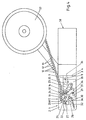
- a tool head 1 is provided, the housing 2 of which has a dovetail-shaped groove (not shown in detail) in the region of an end face 3, with the aid of which the tool head 1 is attached to a corresponding counter surface 4 of a hand gun 5.
- the hand gun 5 has two hand levers 6 and 7 which can be pivoted relative to one another.
- a piston-like extension 8 is thus operatively connected, which can execute a forward stroke directed to the left in FIG. 1 when the hand lever 7 is pivoted in the direction of the hand lever 6.
- the reverse stroke of the extension 8 is directed when the hand lever 7 is released.
- the hand gun 5 with the individual parts described forms one possible Drives for the individual parts of the tool head 1. As a drive, the extension 8 executes a forward stroke according to arrow 9 and a reverse stroke opposite to arrow 9.
- Wire end sleeves 10 each have a metallic sleeve 11 and a plastic collar 12. Their mutual connection in tape form is achieved by spraying the plastic collars 12 against one another, preferably in the area facing away from the metallic sleeve 11, connecting webs 13 being formed here without any appreciable extension, ie the distance between the two Plastic collars are practically determined by their outer diameter.
- the band of wire end sleeves 10 is fed to the tool head 1 through an opening 14 in the housing 2 in such a way that the front end of the band reaches the area of a transport device 15, which here has, as an essential component, a transport wheel 16 which is rotatably supported about an axis 17 is.
- the transport wheel 16 has depressions 18 distributed over its circumference in a regular division, which are matched to the outer diameter of the plastic collar 12 of the wire end ferrules 10 and which are designed and provided for receiving this plastic collar 12.
- a pawl drive with a pawl 19 is provided for driving the transport wheel 16 or switching it clockwise by one division, which is actuated in the first part of the forward stroke of the extension 8 according to arrow 9 and switches the transport wheel 16 further by one division.
- a charging station 20 is formed on the circumference of the transport wheel 16 in a certain relative arrangement, in the area of which the housing 2 has a recess (not shown here) for the lateral insertion of a stripped conductor end into the relevant ferrule 10.
- the pressing takes place in the area of the metallic sleeve 11 with the stripped conductor end.
- Essential components of the crimping station 21 are a fixedly arranged press jaw 22 and an associated movably arranged press jaw 23.
- the press jaw 23 is mounted with the aid of an elongated hole 24 on the axis 17 of the transport wheel 16, but behind it in an offset plane.
- the press jaw 23 is guided in the housing 2 of the tool head 1 in the direction indicated by arrow 9.
- a distance 26 is provided which forms an idle stroke, in such a way that the forward movement of the pawl 19 is limited only to the first part of the forward stroke of the extension 8 until the foremost wire end sleeve has reached the crimping station 21, while only then has the distance 26 been overcome, so that the movable press jaw 23 only starts to move in accordance with arrow 9.
- the connecting web 13 between the foremost wire end sleeve 10 and the subsequent wire end sleeve 10 is severed, in particular torn off, which happens because the movable press jaw 23 presses the foremost wire end sleeve 10 radially outward as seen from the axis 17, that is to say the normal radius of the depressions 18 is exceeded, so that the foremost ferrule 10 shifts radially outwards. It is not only free of the subsequent ferrule without the need for a separate cutting device, but there is also a centering movement between the press jaws 23 and 22 at the same time.
- a blocking device 30 equipped with a pivoting lever 29 is provided.
- the pivot lever 29 is pivotally mounted about an axis 31 against the force of a return spring 32.
- the pivot lever 29 has a sliding surface 33, which is assigned a counter surface 34 on a wedge slide 35.
- the wedge slide 35 is also actuated by the latter in the second part of the forward stroke of the extension 8 and displaced in the direction of the arrow 9, so that the pivot lever 29 of the blocking device 30 is pivoted clockwise and with a cross bolt 36 into the relevant recess 18 of the transport wheel 16 intervening blocking.
- the transport wheel 16 can otherwise be equipped with a stepping mechanism in order to to prevent unintentional turning back and slipping out of the beginning of the tape from end sleeves 10, for example as a result of tension acting on the tape.
- the band of wire end sleeves 10 is otherwise accommodated in a magazine 37 or wound there.
- the ratchet mechanism for the transport wheel 16 is designed to be unlockable in order to consciously exchange an unused strip of band-shaped wire end sleeves 10 for one of a different size.
- the transport wheel 16 and the press jaws 22 and 23 are also interchangeable in order to crimp end sleeves 10 of other dimensions.
- FIG. 2 illustrates a piece of a band made of wire end sleeves 10 which are attached to one another. Between their plastic collars 12 there are connecting webs 13 at the ends. The metallic sleeves 11 protrude freely. In these two parallel planes, the transport wheel 16 engages the plastic collar 12, while the press jaws 22 and 23 are assigned to the planes of the metallic sleeves 11.
- the further exemplary embodiment of the tool illustrated in FIGS. 4 and 5 has a tool head 1 which is based on the tool head 1 according to FIGS. 1 and 3. However, this tool head 1 is not attached to a handgun 5, but to a pneumatic drive 38.
- This pneumatic drive 38 also has an extension 8 which can carry out a forward stroke according to arrow 9 and a reverse stroke opposite to arrow 9 when the drive 38 is triggered.
- the band of wire end sleeves 10 with the plastic collar 12 and the metallic sleeves 11 is also pulled off from the coil-shaped magazine 37 or fed to the housing 2. It passes through the opening 14 of the housing 2 into the region of the transport device 15 with the transport wheel 16, the plastic collar 12 being separated from the Wells 18 are added.
- a tab lever 39 is arranged to be pivotable about an axis 40 on the wedge slide 35 or on a separate part actuated by the extension 8 in the first part of the forward stroke.
- the link lever 39 has a cross pin 41 which engages in the recesses 18 of the transport wheel 16 and, when actuated, switches it by one division.
- the geometries of the tab lever 39 and the pivot lever 29 are coordinated with one another.
Landscapes
- Engineering & Computer Science (AREA)
- Manufacturing & Machinery (AREA)
- Manufacturing Of Electrical Connectors (AREA)
Applications Claiming Priority (2)
| Application Number | Priority Date | Filing Date | Title |
|---|---|---|---|
| DE4241224 | 1992-12-08 | ||
| DE19924241224 DE4241224C1 (de) | 1992-12-08 | 1992-12-08 | Werkzeug zum Verpressen von isolierten Aderendhülsen in Bandform |
Publications (2)
| Publication Number | Publication Date |
|---|---|
| EP0601408A2 true EP0601408A2 (fr) | 1994-06-15 |
| EP0601408A3 EP0601408A3 (en) | 1996-11-27 |
Family
ID=6474640
Family Applications (1)
| Application Number | Title | Priority Date | Filing Date |
|---|---|---|---|
| EP93119036A Withdrawn EP0601408A3 (en) | 1992-12-08 | 1993-11-25 | Tool for crimping insulated wire-end-ferrules in strip form. |
Country Status (2)
| Country | Link |
|---|---|
| EP (1) | EP0601408A3 (fr) |
| DE (1) | DE4241224C1 (fr) |
Cited By (2)
| Publication number | Priority date | Publication date | Assignee | Title |
|---|---|---|---|---|
| WO2021043807A1 (fr) * | 2019-09-05 | 2021-03-11 | Weidmüller Interface GmbH & Co. KG | Insert de sertissage et pince de sertissage |
| CN113615012A (zh) * | 2019-03-05 | 2021-11-05 | 菲尼克斯电气公司 | 用于加工芯线末端套管的料盒和用于压紧芯线末端套管的手工工具 |
Families Citing this family (9)
| Publication number | Priority date | Publication date | Assignee | Title |
|---|---|---|---|---|
| DE4413748A1 (de) * | 1994-04-20 | 1995-11-02 | Josef Krampe | Zangenartiges Werkzeug zum Verdrillen des teilweise freigelegten Endbereichs eines eine Litze als Ader aufweisenden isolierten Leiters |
| DE102008003524B4 (de) | 2008-01-08 | 2009-12-03 | Wezag Gmbh Werkzeugfabrik | Presswerkzeug |
| TWI658659B (zh) | 2017-02-07 | 2019-05-01 | 溫芫鋐 | 自行車線尾套 |
| EP3396796B1 (fr) | 2017-04-25 | 2021-07-21 | WEZAG GmbH & Co. KG | Outil de compression, de sertissage ou de découpe et module d'outils |
| DE102019117856A1 (de) | 2019-07-02 | 2021-01-07 | Phoenix Contact Gmbh & Co. Kg | Magazin zur Verarbeitung von Aderendhülsen und Handwerkzeug zum Verpressen von Aderendhülsen |
| EP3820001B1 (fr) | 2019-11-11 | 2022-08-17 | WEZAG GmbH & Co. KG | Pince à sertir et groupe de pinces à sertir |
| EP3834989B1 (fr) | 2019-12-11 | 2022-11-23 | WEZAG GmbH & Co. KG | Outil pince à main et procédé de montage d'un tel outil |
| DE102020133326A1 (de) * | 2020-12-14 | 2022-06-15 | Harting Electric Gmbh & Co. Kg | Multifunktionales Handwerkzeug |
| EP4243222B1 (fr) | 2022-03-09 | 2024-05-15 | WEZAG GmbH & Co. KG | Capteur de puissance de pince à sertir et pince à sertir |
Citations (5)
| Publication number | Priority date | Publication date | Assignee | Title |
|---|---|---|---|---|
| EP0150397A2 (fr) * | 1984-01-27 | 1985-08-07 | HTS-Elektrotechnik GmbH | Pince manuelle à sertir |
| EP0239529A2 (fr) * | 1986-03-25 | 1987-09-30 | Carl Geisser | Outil à main pour le montage de douilles terminales de câble |
| WO1991014300A1 (fr) * | 1990-03-16 | 1991-09-19 | Zoller & Fröhlich Gmbh & Co. Kg | Outil de sertissage crimp |
| US5113679A (en) * | 1990-06-27 | 1992-05-19 | Burndy Corporation | Apparatus for crimping articles |
| EP0540879A1 (fr) * | 1991-11-04 | 1993-05-12 | Weidmüller Interface GmbH & Co. | Terminaisons pour fils reliées ensemblé sur un support en forme de chaîne et dispositif de transport associé |
Family Cites Families (1)
| Publication number | Priority date | Publication date | Assignee | Title |
|---|---|---|---|---|
| US3710610A (en) * | 1970-06-05 | 1973-01-16 | Bunker Ramo | Wire terminal crimping tool |
-
1992
- 1992-12-08 DE DE19924241224 patent/DE4241224C1/de not_active Expired - Fee Related
-
1993
- 1993-11-25 EP EP93119036A patent/EP0601408A3/de not_active Withdrawn
Patent Citations (5)
| Publication number | Priority date | Publication date | Assignee | Title |
|---|---|---|---|---|
| EP0150397A2 (fr) * | 1984-01-27 | 1985-08-07 | HTS-Elektrotechnik GmbH | Pince manuelle à sertir |
| EP0239529A2 (fr) * | 1986-03-25 | 1987-09-30 | Carl Geisser | Outil à main pour le montage de douilles terminales de câble |
| WO1991014300A1 (fr) * | 1990-03-16 | 1991-09-19 | Zoller & Fröhlich Gmbh & Co. Kg | Outil de sertissage crimp |
| US5113679A (en) * | 1990-06-27 | 1992-05-19 | Burndy Corporation | Apparatus for crimping articles |
| EP0540879A1 (fr) * | 1991-11-04 | 1993-05-12 | Weidmüller Interface GmbH & Co. | Terminaisons pour fils reliées ensemblé sur un support en forme de chaîne et dispositif de transport associé |
Cited By (3)
| Publication number | Priority date | Publication date | Assignee | Title |
|---|---|---|---|---|
| CN113615012A (zh) * | 2019-03-05 | 2021-11-05 | 菲尼克斯电气公司 | 用于加工芯线末端套管的料盒和用于压紧芯线末端套管的手工工具 |
| CN113615012B (zh) * | 2019-03-05 | 2023-10-31 | 菲尼克斯电气公司 | 用于加工芯线末端套管的料盒和用于压紧芯线末端套管的手工工具 |
| WO2021043807A1 (fr) * | 2019-09-05 | 2021-03-11 | Weidmüller Interface GmbH & Co. KG | Insert de sertissage et pince de sertissage |
Also Published As
| Publication number | Publication date |
|---|---|
| EP0601408A3 (en) | 1996-11-27 |
| DE4241224C1 (de) | 1994-01-20 |
Similar Documents
| Publication | Publication Date | Title |
|---|---|---|
| DE2119466C2 (de) | Quetschzange zum Anquetschen von elektrischen Anschlußkontakten an Leiter | |
| DE2820690C2 (de) | Vorrichtung zum Anschlagen einer elektrischen Anschlußklemme an einen Leiterendabschnitt | |
| DE4008515C2 (fr) | ||
| DE4241224C1 (de) | Werkzeug zum Verpressen von isolierten Aderendhülsen in Bandform | |
| DE1615684B1 (de) | Vorschub- und Schneideeinrichtung fuer eine Maschine zum gleichzeitigen Anschlagen mehrerer elektrischer Verbinder | |
| DE19716132C2 (de) | Schraubeneintreibvorrichtung | |
| DE2700884A1 (de) | Werkzeug zum verbinden der beiden haelften eines elektrischen verbinders | |
| EP0562229A2 (fr) | Pince de sertissage pour extrémités des fils | |
| DE1527236C3 (de) | BHndnietzange | |
| DE202009001625U1 (de) | Vereinzelungsvorrichtung zum Abscheren von an einem Vorratsband aufgereihten Werkstücken | |
| DE1502144A1 (de) | Zubringereinrichtung fuer stiftfoermige Gegenstaende an Pressmaschinen | |
| EP0144404B1 (fr) | Procede pour relier deux barres qui se croisent et installation pour realiser ce procede | |
| EP0540879B1 (fr) | Terminaisons pour fils reliées ensemblé sur un support en forme de chaîne et dispositif de transport associé | |
| DE4413748A1 (de) | Zangenartiges Werkzeug zum Verdrillen des teilweise freigelegten Endbereichs eines eine Litze als Ader aufweisenden isolierten Leiters | |
| EP1671407B1 (fr) | Pince a denuder automatique | |
| DE2457350C2 (de) | Einrichtung zum Positionieren der freien Enden mehrerer elektrischer Drähte in vorgegebener Anordnung | |
| DE2718165A1 (de) | Crimpvorrichtung | |
| DE1112154B (de) | Zangenartiges Handwerkzeug zum Anwuergen eines elektrischen Anschlussteiles an einenLeiter | |
| DE10212993B4 (de) | Crimp-Verfahren | |
| DE4205194C1 (en) | Wire stripping pliers e.g. for wires covered with hard isolating material - has swivelling handle joined to attachment, which blocks movement of stripping jaws until pre-set pressure is applied | |
| WO2021043807A1 (fr) | Insert de sertissage et pince de sertissage | |
| DE3508377C2 (de) | Maschine zum Aufquetschbestücken von Kabeladerenden mit Aderendhülsen o.dgl. Anschlußelementen | |
| DE1181766B (de) | Zange zum Kerben von Werkstuecken | |
| DE1465103A1 (de) | Geraet zum Anbringen elektrischer Verbindungsklammern am Polbolzen | |
| DE3911870C2 (fr) |
Legal Events
| Date | Code | Title | Description |
|---|---|---|---|
| PUAI | Public reference made under article 153(3) epc to a published international application that has entered the european phase |
Free format text: ORIGINAL CODE: 0009012 |
|
| AK | Designated contracting states |
Kind code of ref document: A2 Designated state(s): CH DE ES FR GB IT LI NL |
|
| PUAL | Search report despatched |
Free format text: ORIGINAL CODE: 0009013 |
|
| STAA | Information on the status of an ep patent application or granted ep patent |
Free format text: STATUS: THE APPLICATION HAS BEEN WITHDRAWN |
|
| AK | Designated contracting states |
Kind code of ref document: A3 Designated state(s): CH DE ES FR GB IT LI NL |
|
| 18W | Application withdrawn |
Withdrawal date: 19961107 |