EP0600735A2 - Bildausgabegerät und Verfahren, Tintenstrahldruckverfahren und Druckbild nach diesem Verfahren - Google Patents
Bildausgabegerät und Verfahren, Tintenstrahldruckverfahren und Druckbild nach diesem Verfahren Download PDFInfo
- Publication number
- EP0600735A2 EP0600735A2 EP93309654A EP93309654A EP0600735A2 EP 0600735 A2 EP0600735 A2 EP 0600735A2 EP 93309654 A EP93309654 A EP 93309654A EP 93309654 A EP93309654 A EP 93309654A EP 0600735 A2 EP0600735 A2 EP 0600735A2
- Authority
- EP
- European Patent Office
- Prior art keywords
- ink
- recording
- carriage
- head
- Prior art date
- Legal status (The legal status is an assumption and is not a legal conclusion. Google has not performed a legal analysis and makes no representation as to the accuracy of the status listed.)
- Granted
Links
- 238000000034 method Methods 0.000 title claims abstract description 154
- 238000007639 printing Methods 0.000 claims abstract description 129
- 238000006243 chemical reaction Methods 0.000 claims abstract description 77
- 238000007641 inkjet printing Methods 0.000 claims abstract description 43
- 238000011084 recovery Methods 0.000 claims abstract description 36
- 239000003086 colorant Substances 0.000 claims description 91
- 238000007599 discharging Methods 0.000 claims description 42
- 230000008569 process Effects 0.000 claims description 40
- 238000012545 processing Methods 0.000 claims description 33
- 230000008859 change Effects 0.000 claims description 25
- 238000004040 coloring Methods 0.000 claims description 18
- 238000010438 heat treatment Methods 0.000 claims description 18
- 239000003795 chemical substances by application Substances 0.000 claims description 15
- 238000001035 drying Methods 0.000 claims description 12
- 238000003860 storage Methods 0.000 claims description 9
- 238000005406 washing Methods 0.000 claims description 9
- 238000004140 cleaning Methods 0.000 claims description 7
- 235000019646 color tone Nutrition 0.000 claims description 6
- 238000005520 cutting process Methods 0.000 claims description 3
- 239000002759 woven fabric Substances 0.000 claims description 3
- 238000001514 detection method Methods 0.000 claims description 2
- 238000007790 scraping Methods 0.000 claims 2
- 230000003247 decreasing effect Effects 0.000 abstract description 5
- 239000000976 ink Substances 0.000 description 286
- 239000004753 textile Substances 0.000 description 28
- 239000000975 dye Substances 0.000 description 21
- 230000000694 effects Effects 0.000 description 16
- 239000007788 liquid Substances 0.000 description 16
- 239000000126 substance Substances 0.000 description 15
- MTHSVFCYNBDYFN-UHFFFAOYSA-N diethylene glycol Chemical compound OCCOCCO MTHSVFCYNBDYFN-UHFFFAOYSA-N 0.000 description 11
- 239000000123 paper Substances 0.000 description 11
- 239000007787 solid Substances 0.000 description 11
- RTZKZFJDLAIYFH-UHFFFAOYSA-N Diethyl ether Chemical compound CCOCC RTZKZFJDLAIYFH-UHFFFAOYSA-N 0.000 description 10
- 239000003513 alkali Substances 0.000 description 10
- XLYOFNOQVPJJNP-UHFFFAOYSA-N water Substances O XLYOFNOQVPJJNP-UHFFFAOYSA-N 0.000 description 10
- HEMHJVSKTPXQMS-UHFFFAOYSA-M Sodium hydroxide Chemical compound [OH-].[Na+] HEMHJVSKTPXQMS-UHFFFAOYSA-M 0.000 description 9
- XSQUKJJJFZCRTK-UHFFFAOYSA-N Urea Chemical compound NC(N)=O XSQUKJJJFZCRTK-UHFFFAOYSA-N 0.000 description 8
- 238000013461 design Methods 0.000 description 8
- 238000010586 diagram Methods 0.000 description 8
- 238000010025 steaming Methods 0.000 description 8
- LYCAIKOWRPUZTN-UHFFFAOYSA-N Ethylene glycol Chemical compound OCCO LYCAIKOWRPUZTN-UHFFFAOYSA-N 0.000 description 7
- 239000004744 fabric Substances 0.000 description 7
- 239000000835 fiber Substances 0.000 description 7
- 230000006870 function Effects 0.000 description 7
- 239000000463 material Substances 0.000 description 7
- 239000000203 mixture Substances 0.000 description 7
- 230000002829 reductive effect Effects 0.000 description 7
- 229910052727 yttrium Inorganic materials 0.000 description 7
- 239000000872 buffer Substances 0.000 description 6
- 230000007423 decrease Effects 0.000 description 6
- 238000012546 transfer Methods 0.000 description 6
- 229920003169 water-soluble polymer Polymers 0.000 description 6
- 125000001495 ethyl group Chemical group [H]C([H])([H])C([H])([H])* 0.000 description 5
- -1 ketone alcohols Chemical class 0.000 description 5
- 235000021251 pulses Nutrition 0.000 description 5
- 150000003839 salts Chemical class 0.000 description 5
- CDBYLPFSWZWCQE-UHFFFAOYSA-L Sodium Carbonate Chemical compound [Na+].[Na+].[O-]C([O-])=O CDBYLPFSWZWCQE-UHFFFAOYSA-L 0.000 description 4
- UIIMBOGNXHQVGW-UHFFFAOYSA-M Sodium bicarbonate Chemical compound [Na+].OC([O-])=O UIIMBOGNXHQVGW-UHFFFAOYSA-M 0.000 description 4
- 230000015572 biosynthetic process Effects 0.000 description 4
- 238000009835 boiling Methods 0.000 description 4
- 230000007547 defect Effects 0.000 description 4
- 238000001704 evaporation Methods 0.000 description 4
- 230000008020 evaporation Effects 0.000 description 4
- 239000003960 organic solvent Substances 0.000 description 4
- 230000004044 response Effects 0.000 description 4
- UMGDCJDMYOKAJW-UHFFFAOYSA-N thiourea Chemical compound NC(N)=S UMGDCJDMYOKAJW-UHFFFAOYSA-N 0.000 description 4
- 229920000742 Cotton Polymers 0.000 description 3
- KWYUFKZDYYNOTN-UHFFFAOYSA-M Potassium hydroxide Chemical compound [OH-].[K+] KWYUFKZDYYNOTN-UHFFFAOYSA-M 0.000 description 3
- DNIAPMSPPWPWGF-UHFFFAOYSA-N Propylene glycol Chemical compound CC(O)CO DNIAPMSPPWPWGF-UHFFFAOYSA-N 0.000 description 3
- 230000009471 action Effects 0.000 description 3
- 238000007664 blowing Methods 0.000 description 3
- 239000004202 carbamide Substances 0.000 description 3
- 229920002678 cellulose Polymers 0.000 description 3
- 235000010980 cellulose Nutrition 0.000 description 3
- 230000000052 comparative effect Effects 0.000 description 3
- 150000001875 compounds Chemical class 0.000 description 3
- SWXVUIWOUIDPGS-UHFFFAOYSA-N diacetone alcohol Natural products CC(=O)CC(C)(C)O SWXVUIWOUIDPGS-UHFFFAOYSA-N 0.000 description 3
- 230000001788 irregular Effects 0.000 description 3
- 230000007774 longterm Effects 0.000 description 3
- 238000004519 manufacturing process Methods 0.000 description 3
- 229910052751 metal Inorganic materials 0.000 description 3
- 239000002184 metal Substances 0.000 description 3
- 229920000642 polymer Polymers 0.000 description 3
- 239000000985 reactive dye Substances 0.000 description 3
- 230000009467 reduction Effects 0.000 description 3
- 230000009182 swimming Effects 0.000 description 3
- 238000004804 winding Methods 0.000 description 3
- SVTBMSDMJJWYQN-UHFFFAOYSA-N 2-methylpentane-2,4-diol Chemical compound CC(O)CC(C)(C)O SVTBMSDMJJWYQN-UHFFFAOYSA-N 0.000 description 2
- CSCPPACGZOOCGX-UHFFFAOYSA-N Acetone Chemical compound CC(C)=O CSCPPACGZOOCGX-UHFFFAOYSA-N 0.000 description 2
- QGZKDVFQNNGYKY-UHFFFAOYSA-N Ammonia Chemical compound N QGZKDVFQNNGYKY-UHFFFAOYSA-N 0.000 description 2
- PEDCQBHIVMGVHV-UHFFFAOYSA-N Glycerine Chemical compound OCC(O)CO PEDCQBHIVMGVHV-UHFFFAOYSA-N 0.000 description 2
- TWRXJAOTZQYOKJ-UHFFFAOYSA-L Magnesium chloride Chemical compound [Mg+2].[Cl-].[Cl-] TWRXJAOTZQYOKJ-UHFFFAOYSA-L 0.000 description 2
- SECXISVLQFMRJM-UHFFFAOYSA-N N-Methylpyrrolidone Chemical compound CN1CCCC1=O SECXISVLQFMRJM-UHFFFAOYSA-N 0.000 description 2
- 239000004372 Polyvinyl alcohol Substances 0.000 description 2
- FAPWRFPIFSIZLT-UHFFFAOYSA-M Sodium chloride Chemical compound [Na+].[Cl-] FAPWRFPIFSIZLT-UHFFFAOYSA-M 0.000 description 2
- WYURNTSHIVDZCO-UHFFFAOYSA-N Tetrahydrofuran Chemical compound C1CCOC1 WYURNTSHIVDZCO-UHFFFAOYSA-N 0.000 description 2
- GSEJCLTVZPLZKY-UHFFFAOYSA-N Triethanolamine Chemical compound OCCN(CCO)CCO GSEJCLTVZPLZKY-UHFFFAOYSA-N 0.000 description 2
- 229910052784 alkaline earth metal Inorganic materials 0.000 description 2
- 150000001342 alkaline earth metals Chemical class 0.000 description 2
- 230000005540 biological transmission Effects 0.000 description 2
- 150000001768 cations Chemical class 0.000 description 2
- 239000001913 cellulose Substances 0.000 description 2
- 229910017052 cobalt Inorganic materials 0.000 description 2
- 239000010941 cobalt Substances 0.000 description 2
- GUTLYIVDDKVIGB-UHFFFAOYSA-N cobalt atom Chemical compound [Co] GUTLYIVDDKVIGB-UHFFFAOYSA-N 0.000 description 2
- 230000001276 controlling effect Effects 0.000 description 2
- 238000012937 correction Methods 0.000 description 2
- 238000000151 deposition Methods 0.000 description 2
- 238000009792 diffusion process Methods 0.000 description 2
- 150000004676 glycans Chemical class 0.000 description 2
- 239000003595 mist Substances 0.000 description 2
- 238000002156 mixing Methods 0.000 description 2
- 239000004745 nonwoven fabric Substances 0.000 description 2
- 230000003287 optical effect Effects 0.000 description 2
- 229920001223 polyethylene glycol Polymers 0.000 description 2
- 229920001282 polysaccharide Polymers 0.000 description 2
- 239000005017 polysaccharide Substances 0.000 description 2
- 229920002451 polyvinyl alcohol Polymers 0.000 description 2
- BWHMMNNQKKPAPP-UHFFFAOYSA-L potassium carbonate Chemical compound [K+].[K+].[O-]C([O-])=O BWHMMNNQKKPAPP-UHFFFAOYSA-L 0.000 description 2
- 238000004321 preservation Methods 0.000 description 2
- YPFDHNVEDLHUCE-UHFFFAOYSA-N propane-1,3-diol Chemical compound OCCCO YPFDHNVEDLHUCE-UHFFFAOYSA-N 0.000 description 2
- 230000035939 shock Effects 0.000 description 2
- 229910000030 sodium bicarbonate Inorganic materials 0.000 description 2
- 235000017557 sodium bicarbonate Nutrition 0.000 description 2
- 229910000029 sodium carbonate Inorganic materials 0.000 description 2
- 239000000243 solution Substances 0.000 description 2
- 150000005846 sugar alcohols Polymers 0.000 description 2
- 239000004094 surface-active agent Substances 0.000 description 2
- 229920002994 synthetic fiber Polymers 0.000 description 2
- 239000012209 synthetic fiber Substances 0.000 description 2
- 229920001059 synthetic polymer Polymers 0.000 description 2
- 238000012360 testing method Methods 0.000 description 2
- YODZTKMDCQEPHD-UHFFFAOYSA-N thiodiglycol Chemical compound OCCSCCO YODZTKMDCQEPHD-UHFFFAOYSA-N 0.000 description 2
- 229950006389 thiodiglycol Drugs 0.000 description 2
- 229960004418 trolamine Drugs 0.000 description 2
- 239000000984 vat dye Substances 0.000 description 2
- 239000002699 waste material Substances 0.000 description 2
- 238000003466 welding Methods 0.000 description 2
- 238000009736 wetting Methods 0.000 description 2
- PUPZLCDOIYMWBV-UHFFFAOYSA-N (+/-)-1,3-Butanediol Chemical compound CC(O)CCO PUPZLCDOIYMWBV-UHFFFAOYSA-N 0.000 description 1
- ZWVMLYRJXORSEP-UHFFFAOYSA-N 1,2,6-Hexanetriol Chemical compound OCCCCC(O)CO ZWVMLYRJXORSEP-UHFFFAOYSA-N 0.000 description 1
- CYSGHNMQYZDMIA-UHFFFAOYSA-N 1,3-Dimethyl-2-imidazolidinon Chemical compound CN1CCN(C)C1=O CYSGHNMQYZDMIA-UHFFFAOYSA-N 0.000 description 1
- RYHBNJHYFVUHQT-UHFFFAOYSA-N 1,4-Dioxane Chemical compound C1COCCO1 RYHBNJHYFVUHQT-UHFFFAOYSA-N 0.000 description 1
- IXPNQXFRVYWDDI-UHFFFAOYSA-N 1-methyl-2,4-dioxo-1,3-diazinane-5-carboximidamide Chemical compound CN1CC(C(N)=N)C(=O)NC1=O IXPNQXFRVYWDDI-UHFFFAOYSA-N 0.000 description 1
- SMZOUWXMTYCWNB-UHFFFAOYSA-N 2-(2-methoxy-5-methylphenyl)ethanamine Chemical compound COC1=CC=C(C)C=C1CCN SMZOUWXMTYCWNB-UHFFFAOYSA-N 0.000 description 1
- NIXOWILDQLNWCW-UHFFFAOYSA-N 2-Propenoic acid Natural products OC(=O)C=C NIXOWILDQLNWCW-UHFFFAOYSA-N 0.000 description 1
- LCZVSXRMYJUNFX-UHFFFAOYSA-N 2-[2-(2-hydroxypropoxy)propoxy]propan-1-ol Chemical compound CC(O)COC(C)COC(C)CO LCZVSXRMYJUNFX-UHFFFAOYSA-N 0.000 description 1
- 244000215068 Acacia senegal Species 0.000 description 1
- QTBSBXVTEAMEQO-UHFFFAOYSA-M Acetate Chemical compound CC([O-])=O QTBSBXVTEAMEQO-UHFFFAOYSA-M 0.000 description 1
- BVKZGUZCCUSVTD-UHFFFAOYSA-M Bicarbonate Chemical compound OC([O-])=O BVKZGUZCCUSVTD-UHFFFAOYSA-M 0.000 description 1
- UXVMQQNJUSDDNG-UHFFFAOYSA-L Calcium chloride Chemical compound [Cl-].[Cl-].[Ca+2] UXVMQQNJUSDDNG-UHFFFAOYSA-L 0.000 description 1
- BVKZGUZCCUSVTD-UHFFFAOYSA-L Carbonate Chemical compound [O-]C([O-])=O BVKZGUZCCUSVTD-UHFFFAOYSA-L 0.000 description 1
- 229920002134 Carboxymethyl cellulose Polymers 0.000 description 1
- LFQSCWFLJHTTHZ-UHFFFAOYSA-N Ethanol Chemical compound CCO LFQSCWFLJHTTHZ-UHFFFAOYSA-N 0.000 description 1
- 108010010803 Gelatin Proteins 0.000 description 1
- 229920002907 Guar gum Polymers 0.000 description 1
- 229920000084 Gum arabic Polymers 0.000 description 1
- 239000004354 Hydroxyethyl cellulose Substances 0.000 description 1
- 229920001479 Hydroxyethyl methyl cellulose Polymers 0.000 description 1
- 229920000161 Locust bean gum Polymers 0.000 description 1
- 239000007832 Na2SO4 Substances 0.000 description 1
- 241000047703 Nonion Species 0.000 description 1
- 239000004677 Nylon Substances 0.000 description 1
- 229920003171 Poly (ethylene oxide) Polymers 0.000 description 1
- 239000002202 Polyethylene glycol Substances 0.000 description 1
- WCUXLLCKKVVCTQ-UHFFFAOYSA-M Potassium chloride Chemical compound [Cl-].[K+] WCUXLLCKKVVCTQ-UHFFFAOYSA-M 0.000 description 1
- GOOHAUXETOMSMM-UHFFFAOYSA-N Propylene oxide Chemical group CC1CO1 GOOHAUXETOMSMM-UHFFFAOYSA-N 0.000 description 1
- 229920000297 Rayon Polymers 0.000 description 1
- PMZURENOXWZQFD-UHFFFAOYSA-L Sodium Sulfate Chemical compound [Na+].[Na+].[O-]S([O-])(=O)=O PMZURENOXWZQFD-UHFFFAOYSA-L 0.000 description 1
- VMHLLURERBWHNL-UHFFFAOYSA-M Sodium acetate Chemical compound [Na+].CC([O-])=O VMHLLURERBWHNL-UHFFFAOYSA-M 0.000 description 1
- 229920002472 Starch Polymers 0.000 description 1
- SAQSTQBVENFSKT-UHFFFAOYSA-M TCA-sodium Chemical compound [Na+].[O-]C(=O)C(Cl)(Cl)Cl SAQSTQBVENFSKT-UHFFFAOYSA-M 0.000 description 1
- 240000004584 Tamarindus indica Species 0.000 description 1
- 235000004298 Tamarindus indica Nutrition 0.000 description 1
- UWHCKJMYHZGTIT-UHFFFAOYSA-N Tetraethylene glycol, Natural products OCCOCCOCCOCCO UWHCKJMYHZGTIT-UHFFFAOYSA-N 0.000 description 1
- 229920001615 Tragacanth Polymers 0.000 description 1
- 235000021307 Triticum Nutrition 0.000 description 1
- 244000098338 Triticum aestivum Species 0.000 description 1
- 240000008042 Zea mays Species 0.000 description 1
- 235000005824 Zea mays ssp. parviglumis Nutrition 0.000 description 1
- 235000002017 Zea mays subsp mays Nutrition 0.000 description 1
- 238000002835 absorbance Methods 0.000 description 1
- 238000010521 absorption reaction Methods 0.000 description 1
- 235000010489 acacia gum Nutrition 0.000 description 1
- 239000000205 acacia gum Substances 0.000 description 1
- 239000000980 acid dye Substances 0.000 description 1
- 230000000996 additive effect Effects 0.000 description 1
- 238000013019 agitation Methods 0.000 description 1
- 150000001298 alcohols Chemical class 0.000 description 1
- 150000005215 alkyl ethers Chemical class 0.000 description 1
- 125000002947 alkylene group Chemical group 0.000 description 1
- 230000004075 alteration Effects 0.000 description 1
- 150000001412 amines Chemical class 0.000 description 1
- 229910021529 ammonia Inorganic materials 0.000 description 1
- 150000003868 ammonium compounds Chemical class 0.000 description 1
- 239000000305 astragalus gummifer gum Substances 0.000 description 1
- ITHZDDVSAWDQPZ-UHFFFAOYSA-L barium acetate Chemical compound [Ba+2].CC([O-])=O.CC([O-])=O ITHZDDVSAWDQPZ-UHFFFAOYSA-L 0.000 description 1
- 230000008033 biological extinction Effects 0.000 description 1
- 239000007853 buffer solution Substances 0.000 description 1
- 229910052791 calcium Inorganic materials 0.000 description 1
- 239000011575 calcium Substances 0.000 description 1
- VSGNNIFQASZAOI-UHFFFAOYSA-L calcium acetate Chemical compound [Ca+2].CC([O-])=O.CC([O-])=O VSGNNIFQASZAOI-UHFFFAOYSA-L 0.000 description 1
- 239000001639 calcium acetate Substances 0.000 description 1
- 229960005147 calcium acetate Drugs 0.000 description 1
- 235000011092 calcium acetate Nutrition 0.000 description 1
- 239000001110 calcium chloride Substances 0.000 description 1
- 235000011148 calcium chloride Nutrition 0.000 description 1
- 229910001628 calcium chloride Inorganic materials 0.000 description 1
- 239000001768 carboxy methyl cellulose Substances 0.000 description 1
- 235000010948 carboxy methyl cellulose Nutrition 0.000 description 1
- 239000008112 carboxymethyl-cellulose Substances 0.000 description 1
- 239000005018 casein Substances 0.000 description 1
- BECPQYXYKAMYBN-UHFFFAOYSA-N casein, tech. Chemical compound NCCCCC(C(O)=O)N=C(O)C(CC(O)=O)N=C(O)C(CCC(O)=N)N=C(O)C(CC(C)C)N=C(O)C(CCC(O)=O)N=C(O)C(CC(O)=O)N=C(O)C(CCC(O)=O)N=C(O)C(C(C)O)N=C(O)C(CCC(O)=N)N=C(O)C(CCC(O)=N)N=C(O)C(CCC(O)=N)N=C(O)C(CCC(O)=O)N=C(O)C(CCC(O)=O)N=C(O)C(COP(O)(O)=O)N=C(O)C(CCC(O)=N)N=C(O)C(N)CC1=CC=CC=C1 BECPQYXYKAMYBN-UHFFFAOYSA-N 0.000 description 1
- 235000021240 caseins Nutrition 0.000 description 1
- 239000003638 chemical reducing agent Substances 0.000 description 1
- 239000011248 coating agent Substances 0.000 description 1
- 238000000576 coating method Methods 0.000 description 1
- 239000002131 composite material Substances 0.000 description 1
- 239000012141 concentrate Substances 0.000 description 1
- 238000010276 construction Methods 0.000 description 1
- 230000010485 coping Effects 0.000 description 1
- 235000005822 corn Nutrition 0.000 description 1
- 239000013078 crystal Substances 0.000 description 1
- 230000008021 deposition Effects 0.000 description 1
- 239000003599 detergent Substances 0.000 description 1
- 150000001983 dialkylethers Chemical class 0.000 description 1
- ZBCBWPMODOFKDW-UHFFFAOYSA-N diethanolamine Chemical compound OCCNCCO ZBCBWPMODOFKDW-UHFFFAOYSA-N 0.000 description 1
- 238000007598 dipping method Methods 0.000 description 1
- SZXQTJUDPRGNJN-UHFFFAOYSA-N dipropylene glycol Chemical compound OCCCOCCCO SZXQTJUDPRGNJN-UHFFFAOYSA-N 0.000 description 1
- 239000000982 direct dye Substances 0.000 description 1
- 239000000986 disperse dye Substances 0.000 description 1
- 239000002270 dispersing agent Substances 0.000 description 1
- 239000006185 dispersion Substances 0.000 description 1
- 238000004043 dyeing Methods 0.000 description 1
- 239000013013 elastic material Substances 0.000 description 1
- 230000002708 enhancing effect Effects 0.000 description 1
- 238000005530 etching Methods 0.000 description 1
- 150000002170 ethers Chemical class 0.000 description 1
- 235000013312 flour Nutrition 0.000 description 1
- 239000006081 fluorescent whitening agent Substances 0.000 description 1
- 239000008273 gelatin Substances 0.000 description 1
- 229920000159 gelatin Polymers 0.000 description 1
- 235000019322 gelatine Nutrition 0.000 description 1
- 235000011852 gelatine desserts Nutrition 0.000 description 1
- 235000011187 glycerol Nutrition 0.000 description 1
- PCHJSUWPFVWCPO-UHFFFAOYSA-N gold Chemical compound [Au] PCHJSUWPFVWCPO-UHFFFAOYSA-N 0.000 description 1
- 239000010931 gold Substances 0.000 description 1
- 229910052737 gold Inorganic materials 0.000 description 1
- 238000007646 gravure printing Methods 0.000 description 1
- 235000010417 guar gum Nutrition 0.000 description 1
- 239000000665 guar gum Substances 0.000 description 1
- 229960002154 guar gum Drugs 0.000 description 1
- 150000004820 halides Chemical class 0.000 description 1
- 229940051250 hexylene glycol Drugs 0.000 description 1
- WGCNASOHLSPBMP-UHFFFAOYSA-N hydroxyacetaldehyde Natural products OCC=O WGCNASOHLSPBMP-UHFFFAOYSA-N 0.000 description 1
- 235000019447 hydroxyethyl cellulose Nutrition 0.000 description 1
- 230000010365 information processing Effects 0.000 description 1
- 239000004615 ingredient Substances 0.000 description 1
- 239000003112 inhibitor Substances 0.000 description 1
- 230000002401 inhibitory effect Effects 0.000 description 1
- 238000009434 installation Methods 0.000 description 1
- 239000011810 insulating material Substances 0.000 description 1
- 150000002576 ketones Chemical class 0.000 description 1
- 229920005610 lignin Polymers 0.000 description 1
- 230000000670 limiting effect Effects 0.000 description 1
- 235000010420 locust bean gum Nutrition 0.000 description 1
- 239000000711 locust bean gum Substances 0.000 description 1
- 229910001629 magnesium chloride Inorganic materials 0.000 description 1
- 239000002075 main ingredient Substances 0.000 description 1
- FPYJFEHAWHCUMM-UHFFFAOYSA-N maleic anhydride Chemical compound O=C1OC(=O)C=C1 FPYJFEHAWHCUMM-UHFFFAOYSA-N 0.000 description 1
- 239000011159 matrix material Substances 0.000 description 1
- 230000007246 mechanism Effects 0.000 description 1
- 239000013028 medium composition Substances 0.000 description 1
- 229910000000 metal hydroxide Inorganic materials 0.000 description 1
- 150000004692 metal hydroxides Chemical class 0.000 description 1
- 150000002739 metals Chemical class 0.000 description 1
- 229920000609 methyl cellulose Polymers 0.000 description 1
- 239000001923 methylcellulose Substances 0.000 description 1
- 235000010981 methylcellulose Nutrition 0.000 description 1
- 239000011259 mixed solution Substances 0.000 description 1
- 239000008239 natural water Substances 0.000 description 1
- 230000007935 neutral effect Effects 0.000 description 1
- 229920001778 nylon Polymers 0.000 description 1
- 150000007524 organic acids Chemical class 0.000 description 1
- 239000006259 organic additive Substances 0.000 description 1
- 125000006353 oxyethylene group Chemical group 0.000 description 1
- 239000000049 pigment Substances 0.000 description 1
- 229920000728 polyester Polymers 0.000 description 1
- 229920001451 polypropylene glycol Polymers 0.000 description 1
- 229920000915 polyvinyl chloride Polymers 0.000 description 1
- 239000004800 polyvinyl chloride Substances 0.000 description 1
- 229910052700 potassium Inorganic materials 0.000 description 1
- 229910000027 potassium carbonate Inorganic materials 0.000 description 1
- 238000002360 preparation method Methods 0.000 description 1
- 238000002203 pretreatment Methods 0.000 description 1
- 238000003672 processing method Methods 0.000 description 1
- 235000018102 proteins Nutrition 0.000 description 1
- 108090000623 proteins and genes Proteins 0.000 description 1
- 102000004169 proteins and genes Human genes 0.000 description 1
- 230000005855 radiation Effects 0.000 description 1
- 239000002964 rayon Substances 0.000 description 1
- 230000001105 regulatory effect Effects 0.000 description 1
- 239000011347 resin Substances 0.000 description 1
- 229920005989 resin Polymers 0.000 description 1
- 239000004065 semiconductor Substances 0.000 description 1
- 229910052709 silver Inorganic materials 0.000 description 1
- 239000004332 silver Substances 0.000 description 1
- 229910052708 sodium Inorganic materials 0.000 description 1
- 239000011734 sodium Substances 0.000 description 1
- 235000017281 sodium acetate Nutrition 0.000 description 1
- 235000010413 sodium alginate Nutrition 0.000 description 1
- 239000000661 sodium alginate Substances 0.000 description 1
- 229940005550 sodium alginate Drugs 0.000 description 1
- 239000011780 sodium chloride Substances 0.000 description 1
- 229910052938 sodium sulfate Inorganic materials 0.000 description 1
- 235000011152 sodium sulphate Nutrition 0.000 description 1
- 239000002904 solvent Substances 0.000 description 1
- 239000007921 spray Substances 0.000 description 1
- 238000004544 sputter deposition Methods 0.000 description 1
- 239000008107 starch Substances 0.000 description 1
- 235000019698 starch Nutrition 0.000 description 1
- 239000000758 substrate Substances 0.000 description 1
- HXJUTPCZVOIRIF-UHFFFAOYSA-N sulfolane Chemical compound O=S1(=O)CCCC1 HXJUTPCZVOIRIF-UHFFFAOYSA-N 0.000 description 1
- 239000000057 synthetic resin Substances 0.000 description 1
- 229920003002 synthetic resin Polymers 0.000 description 1
- 235000018553 tannin Nutrition 0.000 description 1
- 229920001864 tannin Polymers 0.000 description 1
- 239000001648 tannin Substances 0.000 description 1
- YLQBMQCUIZJEEH-UHFFFAOYSA-N tetrahydrofuran Natural products C=1C=COC=1 YLQBMQCUIZJEEH-UHFFFAOYSA-N 0.000 description 1
- ZIBGPFATKBEMQZ-UHFFFAOYSA-N triethylene glycol Chemical compound OCCOCCOCCO ZIBGPFATKBEMQZ-UHFFFAOYSA-N 0.000 description 1
- 238000011144 upstream manufacturing Methods 0.000 description 1
- 238000007740 vapor deposition Methods 0.000 description 1
- 239000011800 void material Substances 0.000 description 1
- DGVVWUTYPXICAM-UHFFFAOYSA-N β‐Mercaptoethanol Chemical compound OCCS DGVVWUTYPXICAM-UHFFFAOYSA-N 0.000 description 1
Images


Classifications
-
- B—PERFORMING OPERATIONS; TRANSPORTING
- B41—PRINTING; LINING MACHINES; TYPEWRITERS; STAMPS
- B41J—TYPEWRITERS; SELECTIVE PRINTING MECHANISMS, i.e. MECHANISMS PRINTING OTHERWISE THAN FROM A FORME; CORRECTION OF TYPOGRAPHICAL ERRORS
- B41J3/00—Typewriters or selective printing or marking mechanisms characterised by the purpose for which they are constructed
- B41J3/54—Typewriters or selective printing or marking mechanisms characterised by the purpose for which they are constructed with two or more sets of type or printing elements
- B41J3/543—Typewriters or selective printing or marking mechanisms characterised by the purpose for which they are constructed with two or more sets of type or printing elements with multiple inkjet print heads
-
- B—PERFORMING OPERATIONS; TRANSPORTING
- B41—PRINTING; LINING MACHINES; TYPEWRITERS; STAMPS
- B41J—TYPEWRITERS; SELECTIVE PRINTING MECHANISMS, i.e. MECHANISMS PRINTING OTHERWISE THAN FROM A FORME; CORRECTION OF TYPOGRAPHICAL ERRORS
- B41J19/00—Character- or line-spacing mechanisms
- B41J19/18—Character-spacing or back-spacing mechanisms; Carriage return or release devices therefor
- B41J19/20—Positive-feed character-spacing mechanisms
- B41J19/202—Drive control means for carriage movement
-
- B—PERFORMING OPERATIONS; TRANSPORTING
- B41—PRINTING; LINING MACHINES; TYPEWRITERS; STAMPS
- B41J—TYPEWRITERS; SELECTIVE PRINTING MECHANISMS, i.e. MECHANISMS PRINTING OTHERWISE THAN FROM A FORME; CORRECTION OF TYPOGRAPHICAL ERRORS
- B41J2/00—Typewriters or selective printing mechanisms characterised by the printing or marking process for which they are designed
- B41J2/005—Typewriters or selective printing mechanisms characterised by the printing or marking process for which they are designed characterised by bringing liquid or particles selectively into contact with a printing material
- B41J2/01—Ink jet
- B41J2/015—Ink jet characterised by the jet generation process
- B41J2/04—Ink jet characterised by the jet generation process generating single droplets or particles on demand
- B41J2/045—Ink jet characterised by the jet generation process generating single droplets or particles on demand by pressure, e.g. electromechanical transducers
- B41J2/04501—Control methods or devices therefor, e.g. driver circuits, control circuits
- B41J2/04571—Control methods or devices therefor, e.g. driver circuits, control circuits detecting viscosity
-
- B—PERFORMING OPERATIONS; TRANSPORTING
- B41—PRINTING; LINING MACHINES; TYPEWRITERS; STAMPS
- B41J—TYPEWRITERS; SELECTIVE PRINTING MECHANISMS, i.e. MECHANISMS PRINTING OTHERWISE THAN FROM A FORME; CORRECTION OF TYPOGRAPHICAL ERRORS
- B41J2/00—Typewriters or selective printing mechanisms characterised by the printing or marking process for which they are designed
- B41J2/005—Typewriters or selective printing mechanisms characterised by the printing or marking process for which they are designed characterised by bringing liquid or particles selectively into contact with a printing material
- B41J2/01—Ink jet
- B41J2/015—Ink jet characterised by the jet generation process
- B41J2/04—Ink jet characterised by the jet generation process generating single droplets or particles on demand
- B41J2/045—Ink jet characterised by the jet generation process generating single droplets or particles on demand by pressure, e.g. electromechanical transducers
- B41J2/04501—Control methods or devices therefor, e.g. driver circuits, control circuits
- B41J2/0458—Control methods or devices therefor, e.g. driver circuits, control circuits controlling heads based on heating elements forming bubbles
-
- B—PERFORMING OPERATIONS; TRANSPORTING
- B41—PRINTING; LINING MACHINES; TYPEWRITERS; STAMPS
- B41J—TYPEWRITERS; SELECTIVE PRINTING MECHANISMS, i.e. MECHANISMS PRINTING OTHERWISE THAN FROM A FORME; CORRECTION OF TYPOGRAPHICAL ERRORS
- B41J2/00—Typewriters or selective printing mechanisms characterised by the printing or marking process for which they are designed
- B41J2/005—Typewriters or selective printing mechanisms characterised by the printing or marking process for which they are designed characterised by bringing liquid or particles selectively into contact with a printing material
- B41J2/01—Ink jet
- B41J2/17—Ink jet characterised by ink handling
- B41J2/175—Ink supply systems ; Circuit parts therefor
- B41J2/17503—Ink cartridges
- B41J2/17543—Cartridge presence detection or type identification
- B41J2/17546—Cartridge presence detection or type identification electronically
-
- B—PERFORMING OPERATIONS; TRANSPORTING
- B41—PRINTING; LINING MACHINES; TYPEWRITERS; STAMPS
- B41J—TYPEWRITERS; SELECTIVE PRINTING MECHANISMS, i.e. MECHANISMS PRINTING OTHERWISE THAN FROM A FORME; CORRECTION OF TYPOGRAPHICAL ERRORS
- B41J2/00—Typewriters or selective printing mechanisms characterised by the printing or marking process for which they are designed
- B41J2/005—Typewriters or selective printing mechanisms characterised by the printing or marking process for which they are designed characterised by bringing liquid or particles selectively into contact with a printing material
- B41J2/01—Ink jet
- B41J2/21—Ink jet for multi-colour printing
- B41J2/2107—Ink jet for multi-colour printing characterised by the ink properties
-
- B—PERFORMING OPERATIONS; TRANSPORTING
- B41—PRINTING; LINING MACHINES; TYPEWRITERS; STAMPS
- B41J—TYPEWRITERS; SELECTIVE PRINTING MECHANISMS, i.e. MECHANISMS PRINTING OTHERWISE THAN FROM A FORME; CORRECTION OF TYPOGRAPHICAL ERRORS
- B41J29/00—Details of, or accessories for, typewriters or selective printing mechanisms not otherwise provided for
- B41J29/377—Cooling or ventilating arrangements
-
- B—PERFORMING OPERATIONS; TRANSPORTING
- B41—PRINTING; LINING MACHINES; TYPEWRITERS; STAMPS
- B41J—TYPEWRITERS; SELECTIVE PRINTING MECHANISMS, i.e. MECHANISMS PRINTING OTHERWISE THAN FROM A FORME; CORRECTION OF TYPOGRAPHICAL ERRORS
- B41J3/00—Typewriters or selective printing or marking mechanisms characterised by the purpose for which they are constructed
- B41J3/407—Typewriters or selective printing or marking mechanisms characterised by the purpose for which they are constructed for marking on special material
- B41J3/4078—Printing on textile
-
- D—TEXTILES; PAPER
- D06—TREATMENT OF TEXTILES OR THE LIKE; LAUNDERING; FLEXIBLE MATERIALS NOT OTHERWISE PROVIDED FOR
- D06P—DYEING OR PRINTING TEXTILES; DYEING LEATHER, FURS OR SOLID MACROMOLECULAR SUBSTANCES IN ANY FORM
- D06P5/00—Other features in dyeing or printing textiles, or dyeing leather, furs, or solid macromolecular substances in any form
- D06P5/30—Ink jet printing
-
- H—ELECTRICITY
- H04—ELECTRIC COMMUNICATION TECHNIQUE
- H04N—PICTORIAL COMMUNICATION, e.g. TELEVISION
- H04N1/00—Scanning, transmission or reproduction of documents or the like, e.g. facsimile transmission; Details thereof
- H04N1/46—Colour picture communication systems
- H04N1/54—Conversion of colour picture signals to a plurality of signals some of which represent particular mixed colours, e.g. for textile printing
-
- B—PERFORMING OPERATIONS; TRANSPORTING
- B41—PRINTING; LINING MACHINES; TYPEWRITERS; STAMPS
- B41J—TYPEWRITERS; SELECTIVE PRINTING MECHANISMS, i.e. MECHANISMS PRINTING OTHERWISE THAN FROM A FORME; CORRECTION OF TYPOGRAPHICAL ERRORS
- B41J2/00—Typewriters or selective printing mechanisms characterised by the printing or marking process for which they are designed
- B41J2/005—Typewriters or selective printing mechanisms characterised by the printing or marking process for which they are designed characterised by bringing liquid or particles selectively into contact with a printing material
- B41J2/01—Ink jet
- B41J2/015—Ink jet characterised by the jet generation process
- B41J2/04—Ink jet characterised by the jet generation process generating single droplets or particles on demand
- B41J2/045—Ink jet characterised by the jet generation process generating single droplets or particles on demand by pressure, e.g. electromechanical transducers
- B41J2/04501—Control methods or devices therefor, e.g. driver circuits, control circuits
- B41J2/04536—Control methods or devices therefor, e.g. driver circuits, control circuits using history data
-
- B—PERFORMING OPERATIONS; TRANSPORTING
- B41—PRINTING; LINING MACHINES; TYPEWRITERS; STAMPS
- B41J—TYPEWRITERS; SELECTIVE PRINTING MECHANISMS, i.e. MECHANISMS PRINTING OTHERWISE THAN FROM A FORME; CORRECTION OF TYPOGRAPHICAL ERRORS
- B41J2/00—Typewriters or selective printing mechanisms characterised by the printing or marking process for which they are designed
- B41J2/005—Typewriters or selective printing mechanisms characterised by the printing or marking process for which they are designed characterised by bringing liquid or particles selectively into contact with a printing material
- B41J2/01—Ink jet
- B41J2/17—Ink jet characterised by ink handling
- B41J2/175—Ink supply systems ; Circuit parts therefor
- B41J2/17593—Supplying ink in a solid state
-
- B—PERFORMING OPERATIONS; TRANSPORTING
- B41—PRINTING; LINING MACHINES; TYPEWRITERS; STAMPS
- B41J—TYPEWRITERS; SELECTIVE PRINTING MECHANISMS, i.e. MECHANISMS PRINTING OTHERWISE THAN FROM A FORME; CORRECTION OF TYPOGRAPHICAL ERRORS
- B41J29/00—Details of, or accessories for, typewriters or selective printing mechanisms not otherwise provided for
- B41J29/17—Cleaning arrangements
-
- D—TEXTILES; PAPER
- D06—TREATMENT OF TEXTILES OR THE LIKE; LAUNDERING; FLEXIBLE MATERIALS NOT OTHERWISE PROVIDED FOR
- D06B—TREATING TEXTILE MATERIALS USING LIQUIDS, GASES OR VAPOURS
- D06B11/00—Treatment of selected parts of textile materials, e.g. partial dyeing
- D06B11/0056—Treatment of selected parts of textile materials, e.g. partial dyeing of fabrics
- D06B11/0059—Treatment of selected parts of textile materials, e.g. partial dyeing of fabrics by spraying
Definitions
- the present invention relates to a color image output apparatus and method for outputting a color image onto the printing medium by having the image data supplied, and in particular to an image output apparatus and method of the so-called serial scan type of outputting an image while scanning a print head along a predetermined direction relative to the printing medium.
- the invention relates to a method for effecting the print coloring on cloths based on an ink jet system by the use of the heat energy.
- Color image output apparatuses for outputting a color image onto the printing medium with the image data supplied can perform the printing using print agents (color toner, color ink) of four colors of subtractive primary colors i.e., cyan (C), magenta (M) and yellow (Y) and black (Bk) to reproduce vividly three subtractive primary colors or black.
- print agents color toner, color ink
- C cyan
- M magenta
- Y yellow
- Bk black
- image output apparatuses are in some cases desired to use other color print agents than the above colors of C, M, Y and Bk (hereinafter referred to as specializing color, e.g., metallic color or cobalt blue). This occurs when a color which is unable or difficult to represent with C, M, Y, Bk is required in the output image, or when the use of coloring agent such ink or toner is to be reduced.
- specializing color e.g., metallic color or cobalt blue
- some images may be printed only using part of the print colors without requiring all the print colors.
- the inks for use with the textile printing have already high color densities, and still higher density will result in greater ink viscosities, whereby there is a risk that there occurs a trouble in the ink discharge.
- the optical density is to be increased by providing a greater dot diameter, the size or mass of ink droplet to be discharged may not become uniform, resulting in deviated shot positions, whereby there is a risk of producing streaks or unevenness in the connected portions of images, or producing white streaks in the portion on which even density should be expected.
- apparatuses of scanning the print head across the same print surface by multiple times to effect higher print density can not avoid the print speed decreasing.
- Typical of the conventional coloring methods is a screen textile printing of using a silk screen plate to make the printing directly onto the cloths.
- the screen textile printing is a method in which for an original image to be printed, a silk screen plate is prepared for each color used in the original image, and the ink is directly transferred through silk meshes onto the cloths to effect the coloring.
- ink jet recording apparatuses have been put to practical use, which have the functions of a printer, a copying machine or a facsimile apparatus, or are useful as the output unit of a composite electronic equipment including a computer or a word processor, or a work station, and to solve the above problem, a number of recording methods have been proposed to employ such an ink jet recording apparatus for the color printing of discharging the ink directly onto the cloths.
- ink jet recording means of discharging the ink by the use of heat energy
- ink jet recording means (recording head) of discharging the ink by the use of heat energy
- ink jet recording means can be easily fabricated having an arrangement of liquid channels (arrangement of discharge ports or orifices) with high density by having electricity-heat converters, electrodes, liquid channel walls and a ceiling plate formed as films on the substrate through the semiconductor fabrication processes including etching, vapor deposition and sputtering, thereby allowing for further compact constitution, higher recording speed and higher definition in image quality, and this method is expected as one of the coloring methods on the ink jet print system.
- the inks for use with a special ink jet printing method such as textile printing are subjected to severer requirements than with the conventional ink jet recording onto the recording medium such as paper, including:
- a serial type apparatus relies on the serial scan method of scanning in a direction crosswise to the conveying direction (sub-scan direction) of the recording medium.
- the printing of an entire image on the recording medium is achieved in such a way as to repeat the recording operation of printing one line of image by recording means mounted on the carriage movable in a scan direction over the recording medium, feeding the sheet (pitch convey) by a predetermined amount in a sub-scan direction after one line of recording, and then printing the next line of image onto the recording medium as positioned.
- the continuous print length (scan length) must be much longer (approximately 0.6m or more) than with the normal ink jet recording apparatuses as the printers, owing to the requirements from the production speed or with the final products such as clothings.
- the ink jet printing method of discharging the ink from the head by the use of heat energy generated by heat generating elements of the head upon the application of a drive signal the head temperature greatly rises, because of its scanning over the longer length to be performed at one time, whereby it is difficult to maintain a stable discharge during one time of scanning, owing to largely changing ink viscosity. As a result, the ink may not be likely discharged.
- the depositing amount of ink mist onto the head orifice face will be quite enormous, as may occur at the ink discharge due to the longer scanning for one time, causing a clogging of nozzle orifice which will lead to undischarge (wetting undischarge).
- the ink mist deposited in the neighborhood of nozzles is swept away over nozzle openings by contact with the fiber such as fluffs or waste threads present on the surface of cloths, causing a clogging of nozzle which will lead to undischarge of the ink.
- waste threads themselves as above described may clog any of the nozzle openings because there are more chances of making contact with and attaching onto the nozzle openings, thereby causing undischarge. This is a remarkable problem which may occur with the apparatuses having a longer print length, such as those of discharging the ink by the application of drive signals as many as 5 x 10³ times or more in one scan through at least one of the nozzles of head.
- the present invention has been achieved in view of the aforesaid problems, and resides in an image output apparatus, characterized by comprising a plurality of print heads for effecting the printing in corresponding colors respectively onto the printing medium, a carriage on which said plurality of print heads are mountable, scanning means for scanning said carriage relative to the printing medium to form an image by means of said plurality of print heads, and scan range changing means for changing the scan range with said scanning means in accordance with print heads for use in forming the image among said plurality of print heads mounted on said carriage.
- the present invention resides in an image output apparatus as described above, characterized by further comprising storage means for storing conversion data for representing print colors, said storage means provided corresponding to said plurality of print heads respectively, and conversion data changing means for changing said conversion data stored in said storage means.
- the present invention resides in an image output apparatus as described above, characterized in that said scan range changing means and/or said conversion data changing means change(s) said scan range and/or said conversion data in accordance with print colors corresponding to the print heads mounted on said carriage, the number of print heads mounted, and their mounted positions.
- the present invention resides in an image output method for forming an image on the printing medium while scanning a carriage having a plurality of print heads mounted relative to the printing medium, characterized by including a head detecting step for detecting print heads mounted on said carriage, and a scan range changing step for changing said scan range in accordance with the print heads mounted on said carriage.
- said head detecting step is characterized by detecting print colors corresponding to the print heads mounted on said carriage, the number of print heads, and the positions of print heads mounted.
- the image output method of the present invention is characterized by further including a conversion data changing step for changing conversion data for representing color tones corresponding to the print colors in accordance with a detection of said head detecting step.
- the present invention as described above is constituted in such a way that the heads for desired color inks are mountable by an appropriate number, and the contents of a table for expanding conversion data for reproducing color tones are rewritten in accordance with color tones of the heads mounted, or the scan range such as a print range, an idle discharge range or a wiping range, i.e., start position and stop position, is switched in accordance with the number or range of the heads mounted.
- the objects of the present invention can be achieved. That is, it is possible to flexibly cope with the changes of color tones or the change of density or the preservation of density, and improve the throughput by achieving efficient processing in the above range or printing at high density.
- Another object of the present invention is to provide an ink jet printing method for effecting the stable discharge without undischarge in the ink jet printing having a long print length, and which can provide an excellent dyed product or colored matter without image defect.
- a further object of the present invention is to provide an ink jet printing method which can solve the problems of the coloration associated with the above-described ink jet printing method, that is, which can provide a colored matter of high density without blur, without causing a clogging of head, and is excellent in durability or discharge characteristic over the long term.
- the present invention is an ink jet printing method in which a recording head discharges the ink onto the printing medium by the use of the heat energy generated by heat generating elements of a recording head by the application of a drive signal, characterized in that said recording head scans relatively across the printing medium, wherein at least one of nozzles contained in said recording head discharges the ink by the application of drive signals as many as 104 times or more during one scan, and wherein the ink contains a dye from 3.1 wt% to 30 wt% of all the ink, the viscosity being from 1.5 cP to 4 cP, and the surface tension being from 35 dyn/cm to 65 dyn/cm.
- the present invention provides a color ink jet printing method in which a recording head discharges the inks onto the printing medium by the use of the heat energy generated by heat generating elements of a recording head by the application of a drive signal, using the inks at least consisting of black, magenta, cyan and yellow, characterized in that said recording head scans relatively across the printing medium, wherein at least one of nozzles contained in said recording head discharges the ink by the application of drive signals as many as 104 times or more during one scan, and wherein the ink contains a dye from 3.1 wt% to 30 wt% of all the ink, the viscosity being from 1.5 cP to 4 cP, and the surface tension being from 35 dyn/cm to 65 dyn/cm.
- the present inventors have found that the stable discharge can be attained without causing undischarge to provide a colored matter of high density without blur under the conditions where the used ink contains a dye from 3.1 wt% to 30 wt% of all the ink, the viscosity being from 1.5 cP to 4 cP, and the surface tension being from 35 dyn/cm to 65 dyn/cm.
- Another object of the present invention is to provide an ink jet recording apparatus and an ink jet recording method, wherein the recording speed of the ink jet recording apparatus will not decrease even when recording heads for specializing colors are provided.
- An ink jet recording apparatus of the present invention uses a plurality of recording heads for forming an image on the recording medium by discharging the ink, said recording heads facing said recording medium being scanned in a main scan direction relative to said recording medium to form the image consisting of a number of dots of the ink on the recording medium, comprising head mounting means for mounting the plurality of recording heads, selecting means for selecting recording heads to be used for the recording in accordance with a recording mode from among said plurality of recording heads mounted on said head mounting means, and operation control means for effecting a desired operation only for the recording heads selected by said selecting means, wherein said recording heads selected are arranged on said head mounting means along the main scan direction consecutively for each recording mode.
- An ink jet recording method of the present invention uses a plurality of recording heads for forming an image on the recording medium by discharging the ink, said recording heads facing said recording medium being scanned in a main scan direction to form the image on said recording medium, wherein said plurality of recording heads are arranged along the main scan direction consecutively for each recording mode, and said image is formed on the recording medium by selecting recording heads to be used for the recording in accordance with a recording mode from among said plurality of recording heads, and effecting a desired operation only for the recording heads selected.
- the recording heads to be used for the recording are selected in accordance with a recording mode from among the plurality of recording heads, and the recording heads selected in accordance with the recording mode are arranged consecutively, it is possible to record an excellent image with the ink jet recording having wide color reproducibility, without defect, and at sufficient speed, by selecting only necessary recording heads. Also, the longer life of recording heads, with the unit construction of an electrical image processor system, is attained by inhibiting access to recording heads not to be used, resulting in lower production costs and reduced apparatus costs. Also, the recording head to be selected in accordance with the recording mode can be unified, thereby resulting in better replaceability of heads.
- print includes “textile printing”, and broadly means that the image is applied on the print medium such as the cloths or paper.
- examples of the printing medium include cloths, wall papers, papers, OHP films, and so on.
- the present invention is suitable for recording medium having a low water absorbance such as the cloths or wall paper.
- the cloths include all kinds of woven or unwoven fabrics and other knits, without regard to materials, and how to weave or knit.
- the wall papers include pasting sheets for the wall composed of materials of paper, cloth, or synthetic resin sheet of polyvinyl chloride.
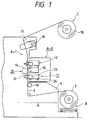
- Fig. 1 is a cross-sectional side view of the mechanical constitution of a printer according to the present invention.
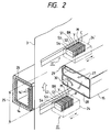
- Fig. 2 is a perspective view showing a constitutional example around a printer head.
- Fig. 3 is a block diagram showing an electrical configuration of the printer as shown in Fig. 1.
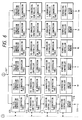
- Fig. 4 is a block diagram.
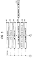
- Fig. 5 is a block diagram showing the data flow through a part of constitution within a control board in Fig. 3.
- Figs. 6 and 7 are block diagrams.
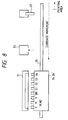
- Fig. 8 is an explanation view typically showing recovery means for the head as shown in Fig. 1.
- Fig. 9 is a view for explaining the movement range of a carriage with the head mounted on the carriage.
- Fig. 10 is an explanation view where upper and lower carriages have different heads mounted.
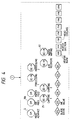
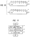
- Fig. 11 is a flowchart showing the processing according to the head mounted on the carriage.
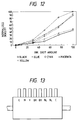
- Fig. 12 is a diagram for explaining the normalized density of the ink for each color relative to the ink shot amount.
- Fig. 13 is an explanation view where a head with higher density color is mounted on the carriage.
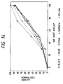
- Fig. 14 is a diagram showing the normalized density of the ink for each color relative to the ink shot amount.
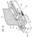
- Fig. 15 is a view showing the main part of an ink jet printing apparatus according to the present invention.
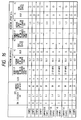
- Fig. 16 is a table showing the characteristics of each ink and the recorded results in examples and a comparative example in example 3.
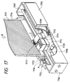
- Fig. 17 is a perspective view showing the essential part of an ink jet recording apparatus according to the present invention.
- Fig. 18 is a front view showing the arrangement of recording heads.
- Fig. 19 is a block diagram showing the constitution of a drive system for the recording heads.
- Fig. 20 is a view for explaining the wiping range with a blade.
- Figs. 21A and 21B are views for explaining the movement range for a head holder.
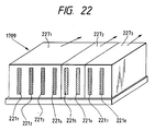
- Fig. 22 is a typical view showing the constitution of a unit.
- Fig. 1 shows a constitutional example of an ink jet printer as a textile printing apparatus according to the first embodiment
- Fig. 2 shows an enlarged perspective view of its essential part.
- the textile printing is largely comprised of a cloths supply unit B for delivering the pretreated cloths for the textile printing which is wound as a roll, a main unit for performing the printing by using an ink jet head while precisely feeding the cloths delivered, and a winding unit C for winding the printed cloths after drying them.
- the main unit A further comprises a precision feeding unit A-1 for the cloths including a platen and a print unit A-2.
- Pretreated roll-like cloths 3 are delivered from the cloths supply unit and fed stepwise into the main unit A.
- the cloths 3 which have been fed stepwise are positioned in a first print unit 11 with the print surface regulated flat by a platen 12 on the back side, and printed by the ink jet head 13 on the front side. Every time one line of print is terminated, the cloths are fed by a predetermined step, and then dried through the heating by a heating plate 14, in addition to the hot air from the surface supplied/exhausted by a hot air duct 15. Subsequently, in a second print unit 11', the over-printing is performed in the same way as in the first print unit.
- the cloths printed are dried again by a post drying unit 16 composed of a heating plate and a heater (or hot air), guided by a guide roll 17, and wound around a winding roll 18. And the wound cloths are removed from the main device, and subjected to a batch processing including coloring, washing, and drying to provide the final products.
- a post drying unit 16 composed of a heating plate and a heater (or hot air), guided by a guide roll 17, and wound around a winding roll 18.
- a post drying unit 16 composed of a heating plate and a heater (or hot air), guided by a guide roll 17, and wound around a winding roll 18.
- the wound cloths are removed from the main device, and subjected to a batch processing including coloring, washing, and drying to provide the final products.
- the cloths 3 of printing medium are fed stepwise in an upper direction as shown.
- a first carriage 24 which can mount the ink jet heads for Y, M, C, Bk and specializing colors S1 to S4, i.e., eight ink jet heads in total (in the figure, there are mounted heads for Y, M, C, Bk and S1 to S4).
- the ink jet head (print head) in this embodiment uses elements for generating the heat energy to cause film boiling in the ink as the energy used to discharge the ink.
- Each head has 256 discharge orifices arranged at a density of 400DPI (dots/inch).
- a drying unit 25 comprised of the heating plate 14 for heating from the back side, and the hot air duct 15 for drying from the front side.
- Heat transfer surface of the heating plate 14 can provide storing heating from the back side with the vapor of high temperature and high pressure passing through a hollow inside.
- fins 14' for the collection of heat are provided to concentrate the heat on the back side of the cloths 3 efficiently.
- the opposite side of the heating plate to the cloths 3 is covered with a heat insulating material 26 to prevent the heat loss due to heat radiation.
- the drying effect is further enhanced by blowing dry hot air from a supply duct 27 disposed downstream to apply the air of lower humidity to the drying cloths. And the air containing sufficient moisture and flowing in the opposite direction to a conveying direction of the cloths is sucked through a suction duct 28 disposed upstream by a much greater amount than a blowing amount, so that evaporated water contents are prevented from wetting and bedewing surrounding mechanical components.
- a supply source of hot air is provided on the rear side of Fig. 2, and the suction is performed from the fore side, so that the pressure difference between a blow-off opening 29 and a suction opening 30 placed opposed to the cloths is rendered even over the entire area in a longitudinal direction.
- Air blowing/suction unit is offset downstream relative to a center of the heating plate provided on the back side, so that the air may be directed to sufficiently heated portion.
- the first print unit 11 can strongly dry a quantity of water contents in the ink including a reducer which has been absorbed into the cloths.
- a second print unit 11' which is comprised of a second carriage 24' of the same constitution as the first carriage.
- the first carriage 24 and the second carriage 24' are unified beforehand or via an appropriate connecting member, and a drive source for driving them and a transmission gear may be commonly used.
- an ink supply unit for reserving the ink and supplying a necessary amount of ink to the head, comprising an ink tank and an ink pump. Its main body and the head are connected via an ink supply tube or the like, whereby normally the amount of ink equal to discharged amount from the head is automatically supplied owing to capillary action. Also, in the head recovery operation, the ink is compulsorily supplied by an ink pump to the head. And the head and the ink supply unit are mounted to the carriage separately provided, which is reciprocated in the directions as indicated by the arrow in Fig. 2 by a drive unit, not shown.
- a head recovery unit at a site opposed to the head at a home position (wait position) to maintain ink discharge stability of the head, which performs the operation as described below. That is, it performs a capping of the head at the home position to prevent evaporation of ink from inside the nozzles of the head 9 when not in operation (capping operation).
- Figs. 3 and 4 show the configuration of an ink jet printer in this embodiment and a constitutional example of its operation unit, respectively, and Figs. 5 to 7 show conceptually the internal constitutions of a control board 102 as shown in Fig. 3 along the flow of data.
- Image data for printing as well as color pallet data for determining a mixture ratio of Y, M, C or specializing color to reproduce excellently the colors selected by the designer, are sent from a host computer H via an interface (herein GPIB) to a control board 102, as disclosed in Japanese Patent Application No. 4-203973.
- GPIB interface
- a device for sending image data is not specifically limited, and the transfer form may be via a network, or off-line via a magnetic tape.
- the control board 102 controls the overall apparatus, and is comprised of CPU 102A, ROM 102B having stored various programs, RAM 102C having various register areas and a working area, and each section as shown in Figs. 5 to 7 and other figures.
- 103 is an operation/display unit having an operation board for the operator to issue a desired instruction to the printer P and a display for displaying a message to the operator.
- 104 is a cloths supply device comprising a motor for conveying the print medium such as cloths.
- 105 is a driver unit input/output unit for driving various motors (suffixed with "M”) as shown in Fig.
- 107 is a relay board for receiving and supplying information concerning each head (e.g., presence or absence of a head or the color presented by the head) to the control board 102, as well as supplying a drive signal to each head. This information is transferred to the host computer H to demand the transfer of color pallet data for a color to be used, and additionally is used for the recognition of the range of mounting a head on the carriages 24, 24' and the setting of the scan range.
- 111 is a drive unit such as a motor for causing the carriages 24, 24' to scan.
- image data to be printed is received from the host computer H, its image data is stored via a GPIB interface 501 and a frame memory controller 504 into an image memory 505 (see Fig. 5).
- the image memory in this embodiment has a capacity of 124 Mbyte, data of A1 size being composed of pallet data of 8 bits. That is, one pixel consists of 8 bits.
- 503 is a DMA controller for speeding up the memory transfer. After the transfer from the host computer H is terminated, the printing can be started through a predetermined processing.
- the host computer connected to the printer in this embodiment transfers image data as a raster image. Since each print head has a plurality of ink discharge nozzles in a longitudinal direction thereof, the arrangement of image data must be converted to be matched with the print head. This data conversion is performed by a raster @ BJ conversion controller 506. And the data converted by this raster @ BJ conversion controller 506 is supplied through enlargement feature of a subsequent enlargement controller 507 for enlarging variably image data to a pallet conversion controller 508. Note that the data before the enlargement controller 507 has been transmitted from the host computer, and consists of 8-bit pallet signal in this embodiment. And this pallet data (8 bits) is commonly passed to a processor (hereinafter described) for each print head, and processed therein.
- a processor hereinafter described
- the pallet conversion controller 508 supplies pallet data and conversion tables for corresponding colors input from the host computer H to a conversion table memory 509.
- the number of reproducible color types is 256, i.e., from 0 to 255, wherein an appropriate table is expanded into a table memory 509 corresponding to each color.
- the pallet conversion table memory 509 fulfills its function with conversion data written at an address position for pallet data. That is, when pallet data is supplied as the address, access to the memory is made in a read mode.
- the pallet conversion controller 508 performs the management of pallet conversion table memory 509 and interfaces between the control board 102 and the pallet conversion table memory 509.
- a circuit for setting the quantity of specializing color to be mixed (a circuit for multiplying the output by from 0 to 1 times) is inserted between it and the next-step HS system comprising an HS controller 510 and an HS conversion table memory 511, wherein its setting quantity can be variable.
- the HS conversion controller 510 and the HS conversion table memory 511 make a correction for dispersion in print density corresponding to each discharge orifice of each head, based on data measured by a head characteristic meter 108 including an appropriate density unevenness correction unit. For example, data conversion is performed to be denser for discharge orifices with lower density (smaller discharge amount), and to be thinner for discharge orifices with higher density (greater discharge amount), and no data conversion is performed for discharge orifices with medium density. This processing will be described later.
- a ⁇ - conversion controller 512 and a ⁇ - conversion table memory 513 subsequently provided are involved in table conversion for making the overall density denser or thinner for each color. For example, when none is performed, this is a linear table. 0 is output when 0 is input 100 is output when 100 is input 210 is output when 210 is input 255 is output when 255 is input
- a binarization controller 514 at the next step has a pseudo gradation function, in which it inputs 8-bit gradation data and outputs binarized pseudo gradation data consisting of one bit. Conversion from multi-value data to binary data may be made according to a dither matrix, or an error diffusion method, which is used in this embodiment, and in any case, though not detailed, other methods may be adopted as far as gradation representation can be made by the number of dots per unit area.
- Binarized data hereby is stored in a buffer memory 515, and then used as the drive data for each print head. And binary data output from each buffer memory is in the form of C, M, Y, Bk, and S1 to S4. As binarized signal for each color is subjected to similar processing, binary data C is noted herein and explained with reference to Fig. 7. Note that the same figure shows the configuration of a print color cyan, but the same configuration applies for each color.
- Fig. 7 is a block diagram showing a circuit configuration following a buffer memory 515 as shown in Figs. 5 and 6.
- Binarized signal C is output to a sequential multi-scan generator 522 (hereinafter referred to as an SMS generator), but is also supplied to a selector 519 because the test print for a single apparatus may be practiced by pattern generators 517, 518.
- this switching is controlled by a CPU of the control board 102, so that data from the binary pattern controller 517 is selected to practice the test print when the operator performs a predetermined operation on the operation unit 103 (see Fig. 3). Accordingly, data from the binary controller 514 (buffer memory 516) is normally selected.
- 520 is a logo input portion inserted between the selector 519 and the SMS generator 522, which can deal with the printing of logo, because in the textile printing, a logo mark such as a maker and a bland of designer is often attached at an end portion of the cloth.
- Its constitution may comprise, for example, a memory for storing logo data, and a controller for controlling the print position.
- the SMS generator 522 prevents uneven density of image due to changing discharge amount for each nozzle.
- Multi-scan has been proposed in Japanese Patent Application No. 4-79858, for example.
- the image quality is made preferential by performing the multi-scan, or discharging the ink through a multiple of discharge orifices for one pixel, or the higher speed is made preferential without performing such multi-scan, this designation being made by appropriate input means, for example, through the operation/display unit 103 or host computer H.
- the buffer memory 524 is a memory for correcting the physical position of head, i.e., the disposition between the upper and lower print units or between each head in Fig. 2, wherein image data is once entered in this memory, and output at a timing according to the physical position of head. Accordingly, this buffer memory 524 has a different capacity for each print color.
- data is sent via the head relay board 107.
- Fig. 8 shows typically so-called recovery means for effecting a processing to make the discharge condition more excellent for the head as shown in Figs. 1 and 2.
- a capping member 51 has a function of preventing the discharge face of head from drying out, in such a manner as to cover the discharge face of head with the capping member 51 during the non-printing or in stand-by (hereinafter referred to as a capping).
- a capping into an idle discharge box 53 is discharged the thicker ink residing inward of the discharge orifices of heads, the thicker ink being discharged from S4 head to C head in succession while the carriage 24 or 24' is moving along a shaft 55.
- a wiping member 57 is an elastic member or a porous member for removing foreign matter attached onto the discharge face of head, in such a manner as to make engagement with and wipe out the discharge faces of heads, successively, from S4 head to C head, in the course of the movement of the carriage 24 or 24'.
- Fig. 9 shows the carriage movement range required to effect a discharge operation into the idle discharge box when four heads for specializing colors are mounted in addition to basic colors for the printing (i), and the carriage movement range when two heads for cyan are mounted without the use of specializing colors (ii).
- the higher printing speed it is preferable for the higher printing speed to switch the movement distance of carriage by recognizing the number of heads mounted, or the mounting range, that is, the movement distance L1 is required when eight heads are mounted, while L2 is required when five heads are mounted.
- the used ink is necessary to change because the feature of design may vary in accordance with the usage after processing the cloths.
- the very denser printing may be required.
- the over-printing is performed by multiple scanning over the same printing surface to enhance the density, but this necessarily results in decreased print speed.
- the head mounting area for specializing colors on the carriage is used to mount a plurality of heads corresponding to denser print colors.
- an image processing system as shown in Figs. 5 to 7 is operated as follows. That is, in the pallet conversion table 508 of Fig. 6, C conversion table is left intact, M conversion table is replaced with C conversion table, Y conversion table is replaced with M conversion table, Bk conversion table is replaced with Y conversion table, and S1 conversion table is replaced with K conversion table. And S2 to S4 conversion tables are set at "00" to suppress the output. Also, HS conversion table and ⁇ conversion table at the next step and beyond are likewise replaced.
- the binary output 516 of Fig. 6 becomes C, C, M, Y and Bk.
- the inclination of ⁇ conversion table for cyan be reduced a slight degree to obtain a desired decrease in density.
- Fig. 10 shows an example wherein two magenta heads are mounted on the upper carriage, and two specializing color heads S1 are mounted on the lower carriage.
- the table for the image processing system may be appropriately switched, even when different heads are mounted on the upper and lower carriages.
- Fig. 11 shows an example of processing procedure for setting the content of conversion table and the scan range in accordance with the head mounted on the carriage.
- the heads mounted on the carriage are identified, that is, in respects of the colors, the number and the range of heads mounted.
- means for identifying the number or range of heads mounted may involve measuring the head line-toline impedance with the signal line between the relay board and the head of Fig. 3 and making an identification through CPU 102A, or making a judgment through on/off operation of a switch disposed at the head mounting position on the carriage.
- an invention as disclosed in Japanese Laid-Open Patent Application No. 2-187343 is applicable in which the print head of printer has means for presenting its own information (pattern cutting), which can be identified on the printer main body side. Such means for presenting that information may rely on the use of an EPROM or a DIP switch.
- that information may be an ink color for use with the print head, whereby the colors, the number or the range can be identified by the printer reading that information. Further, the operator can input that information by using the operation/display unit 103.
- control board 102 issues a required notification to the host computer H, and expands conversion data sent in response thereto into conversion tables 509, 511, 513 (step S3). Further, it sets the scanning range in idle discharge, wiping, and print area, as described in Figs. 9 and 10, in accordance with the number or range of mounted heads (step S5).
- the present invention may be effectively applied in either case where all or part of the print heads are detachable from the carriage, or all the heads are fixed without easy detachment premised. It will be understood that to allow for the setting of the scanning range only based on the information of the number of heads, when they are detachable therefrom, they may be arranged not to produce any gap in the head mounted portion on the carriage. Also, it will be understood that when all the heads are fixed, or when only part of the mounted heads are used for the printing, the information of used heads may be input, or identified by the host computer H analyzing the colors of original picture to make the setting of the scan range in accordance therewith.
- a second embodiment will be now described particularly noting the enhanced print density.
- This embodiment can adopt the same apparatus constitution and processing procedure as those of the first embodiment, but this embodiment is suitable for obtaining a desired print density particularly when printing onto the cloths.
- Fig. 12 shows the relation between ink shot amount and color density.
- the axis of abscissas indicates the ink shot amount with the maximum shot amount per unit area being 100.
- the density of black and specializing color blue is approximately half that of yellow, magenta and cyan.
- a multiplicity of heads for the color for which higher density is desired i.e., two heads for each of black and blue, are mounted in the head mounting area on the carriage as shown in Fig. 13.
- the binary output 516 of Fig. 6 becomes C, M, Y, Bk and Bk.
- the inclination of ⁇ conversion table for black and blue be reduced a slight degree to obtain a desired decrease in density.
- Fig. 14 shows the density when two heads of black and blue are mounted, as compared with Fig. 12. It is apparent that black and blue can represent the density equivalent to that of other three colors.
- the density for the color can be enhanced. Note that the order of print heads or mixing the colors in this embodiment is not changed, and there is no change in color tint.
- step S1 the heads mounted on the carriage are identified, that is, in respects of the colors, the number and the range of heads mounted. Based on such identified results, the control board 102 issues a required notification to the host computer H, and expands conversion data sent in response thereto into conversion tables 509, 511, 513 (step S3). Further, if it sets the scanning range in idle discharge, wiping, and print area, as described in Figs. 9 and 10, in accordance with the number or range of mounted heads, the processing of step S5 is performed, or otherwise step 5 is deleted or skipped.
- an appropriate number of heads for the ink of desired color tint can be mounted, and by rewriting the contents of table for the expansion of conversion data to reproduce the color tint in accordance with the color tint of the head mounted, or switching the scanning range, i.e., the start position and the stop position, in print area, idle discharge area or wiping area in accordance with the number or range of mounted heads, it is possible to flexibly cope with the change of color tint used, the change of density or the steadiness of density, thereby improving the throughput by efficiently performing the processing in the above area or the high density print.
- the present invention has been described in connection with the first and second embodiment exemplifying a textile printing apparatus of ink jet recording system, it will be understood that the present invention is not limited to the ink jet printing system, but can be embodied in various printing systems.
- the present invention brings about excellent effects particularly in the print head or printing apparatus of the system of having means for generating the heat energy (e.g., electricity-heat converters or laser beam) as the energy for use in discharging the ink and causing a state change in the ink due to the heat energy, among the various ink jet printing systems.
- the higher density and higher precision printing can be attained.
- the constitution of the recording head in addition to the combination of the discharging orifice, liquid channel, and electricity-heat converter (linear liquid channel or right-angled liquid channel) as disclosed in the above-mentioned respective specifications, the constitution by use of U.S. Patent 4,558,333 or 4,459,600 disclosing the constitution having the heat acting portion arranged in the flexed region is also included in the present invention.
- the present invention can be also effectively made the constitution as disclosed in Japanese Laid-Open Patent Application No. 59-123670 which discloses the constitution using a slit common to a plurality of electricity-heat converters as the discharging portion of the electricity-heat converter or Japanese Laid-Open Patent Application No. 59-138461 which discloses the constitution having the opening for absorbing pressure wave of heat energy correspondent to the discharging portion. That is, according to the present invention, the printing can be performed securely and efficiently in whatever form the print head may be formed.
- the present invention is effective for a print head secured to the main device, a print head of the freely exchangeable chip type which enables electrical connection to the main device or supply of ink from the main device by being mounted on the main device, or a print head of the cartridge type having an ink tank integrally provided on the print head itself.
- a restoration means for the recording head, a preliminary auxiliary means, etc., provided as the constitution of the recording device of the present invention is preferable, because the effect of the present invention can be further stabilized.
- Specific examples of these may include, for the recording head, capping means, cleaning means, pressurization or suction means, electricity-heat converters or another type of heating elements, preliminary heating means according to a combination of these, and preliminary discharging means for discharging apart from the printing.
- the ink is considered as the liquid in the embodiments of the present invention as above described, other inks may be also usable which are solid below room temperature and will soften or liquefy at or above room temperature, or liquefy when a use print signal is issued as it is common with the ink jet device to control the viscosity of ink to be maintained within a certain range of the stable discharge by adjusting the temperature of ink in a range from 30°C to 70°C.
- the ink which will stiffen in the shelf state and liquefy by heating may be used.
- the use of the ink having a property of liquefying only with the application of heat energy such as those liquefying with the application of heat energy in accordance with a print signal so that liquid ink is discharged, or already starting solidifying upon reaching the printing medium, is also applicable in the present invention.
- the ink may be held as liquid or solid in recesses or through holes of a porous sheet, which is placed opposed to electricity-heat converters, as described in Japanese Laid-Open Patent Application No. 54-56847 or No. 60-71260.
- the most effective method for the ink as above described in the present invention is based on the film boiling.
- the present invention is applicable in the form of an image output terminal for use in an information processing equipment such as a computer, a copying machine in combination with a reader, or a facsimile terminal equipment having the transmission and reception feature.
- a preferred embodiment of the ink jet printing method will be now described in which a stable discharge can be performed without causing undischarge in the ink jet printing having a long print length, thereby providing an excellent colored matter without image defects.
- the ink for use in the present invention is composed of coloring matter, water, organic solvent and additive agent.
- the coloring material is preferably a dye, as far as it is colorable on the printing medium.
- examples include acid dye, direct dye, cation dye, reactive dye, disperse dye, vat dye and soluble vat dye.
- One or more kinds of these dyes are contained in the ink, and can be used together with a dye of different hue, its use amount being typically from 3.1wt% to 30wt% of the total amount of ink, preferably from 3.5wt% to 25wt%, and particularly for black ink, preferably from 5wt% to 20wt%, to obtain a sufficient coloration on the printing medium.
- the amount of water which is preferable for the main component of the ink is from 10wt% to 93wt% of the total amount of ink, preferably from 25wt% to 87wt%, and more preferably from 30wt% to 80wt%.
- organic solvent may include, for example, ketone or ketone alcohols such as acetone and diacetone alcohol, ethers such as tetrahydrofuran and dioxane, oxyethylene or oxypropylene addition polymers such as diethylene glycol, triethylene glycol, tetraethylene glycol, dipropylene glycol, tripropylene glycol, polyethylene glycol, and polypropylene glycol, glycol, alkylene glycols in which alkylene group contains two to six atoms, such as ethylene glycol, propylene glycol, trimethylene glycol, butylene glycol, 1,2,6-hexantriol, and hexylene glycol, polyhydric alcohol lower alkylethers such thiodiglycol, glycerin, ethylene glycol monomethyl (or ethyl) ether, diethylene glycol monomethyl (or ethyl) ether, triethylene glycol monomethyl (or ethyl) ether, polyhydric alcohol lower dial
- the content of water soluble organic solvent is typically from 2wt% to 60wt% of the total ink weight, and preferably from 5wt% to 50wt%.
- the medium as cited above can be used singly or in combination, the most preferable liquid medium composition is the solvent containing at least one kind of polyhydrix alcohol.
- the solvent containing at least one kind of polyhydrix alcohol is the solvent containing at least one kind of polyhydrix alcohol.
- the main ingredients of the ink for use with the present invention are as follows, although other well-known various agents such as dispersant, surface active agent, viscosity control agent, surface tension control agent, fluorescent whitening agent may be added as necessary.
- viscosity control agents such as polyvinyl alcohol, celluloses, and water soluble resin, surface active agent of cation or nonion type, surface tension control agents such as diethanolamine and triethanolamine, pH control agent with buffer solution, and mildew resistant agent.
- a particularly important point in the ink jet print method of the present invention is that the ink viscosity is controlled in a range from 1.5cP to 4cP, preferably from 2.0cP to 3.8cP, and the surface tension is controlled in a range from 35dyn/cm to 65dyn/cm, preferably from 35dyn/cm to 62dyn/cm. Within such ranges, the objects of the present invention can be achieved.
- the ink material must be controlled under severer conditions than the ink used in the conventional recording.
- the undischarge may abruptyl increase, or the stable discharge may fail due to increased viscosity by heating. If the viscosity is lowered below 1.5cP, more blur will occur, or the discharge becomes unstable (occurrence of satellite).
- the length of undischarge (length of void arising on the cloth), when not discharged, may extend over several tens centimeters, when the surface tension is 35 dyn/cm or less. That is, the recovery of undischarge is not allowed smoothly. If there is even one undischarge extending over several tens centimeters, the cloth is unusable, unpreferably.
- the effects of the present invention in the ink jet printing method having a longer print length can be obtained by allowing both the viscosity and the surface tension to fall within the range of the present invention, and if either one of them is out of this range, the effects of the present invention can not be obtained.
- the viscosity and the surface tension of the ink for use with the present invention can be easily controlled by the technicians skilled in the art by appropriately selecting the kind or amount of dyes and organic solvents used, in combination, or by adding various kinds of addition agents.
- the printing medium for use in the present invention is preferably the cloths, the material making up the cloths is not particularly limitative, but examples include natural fibers, regenerated fibers, semi-synthetic fibers, and synthetic fibers such as cotton, silk, nylon, polyester, rayon, and acetate.
- the above fibers can be used in the form of woven, knit or non woven fabrics.
- the cloths have 0.01wt% to 5wt% of alkaline substance contained, when the ink containing a reactive dye is used, or generally, the cloths have 0.01wt% to 20wt% of a substance selected from a group of water soluble metallic salt, water soluble polymer, urea, and thiourea contained therein, from the viewpoints of preventing the fluff or blur.
- alkaline substance examples include alkaline metal hydroxide such as sodium hydroxide and potassium hydroxide, amines such as mono-, di-, or tri-ethanolamine, and alkaline metal carbonate or hydrogencarbonate such as sodium carbonate, potassium carbonate and sodium hydrogencarbonate. Further, they include organic acid metallic salt such as calcium acetate and barium acetate, ammonia and ammonium compounds. Also, sodium trichloroacetate which becomes alkaline substance under the steaming and drying may be used. Particularly preferable alkaline substance may be sodium carbonate and sodium bicarbonate for use in coloring of reactive dye.
- alkaline metal hydroxide such as sodium hydroxide and potassium hydroxide
- amines such as mono-, di-, or tri-ethanolamine
- alkaline metal carbonate or hydrogencarbonate such as sodium carbonate, potassium carbonate and sodium hydrogencarbonate.
- organic acid metallic salt such as calcium acetate and barium acetate, ammonia and ammonium compounds.
- sodium trichloroacetate which
- water soluble polymer examples include starch substances such as corn and wheat flour, cellulose substances such as carboxymethyl cellulose, methyl cellulose and hydroxyethyl cellulose, polysaccharides such as sodium alginate, gum arabic, locust bean gum, tragacanth gum, guar gum, and tamarind seeds, protein substances such as gelatin and casein, and natural water soluble polymers such as tannin type substance and lignin type substance.
- examples of synthetic polymer include polyvinyl alcohol compounds, polyethylene oxide compounds, acrylic acid type water soluble polymer, and maleic anhydride type water soluble polymer. Among them, polysaccharide polymer and cellulose polymer are preferable.
- water soluble metallic salt examples include compounds having a pH of 4 to 10 and making typical ionic crystals such as halides of alkaline metal and alkaline earth metal.
- Typical examples of such compound include alkaline metals such as NaCl, Na2SO4, KCL and CH3COONa, and alkaline earth metals such as CaCl2 and MgCl2.
- alkaline metals such as NaCl, Na2SO4, KCL and CH3COONa
- alkaline earth metals such as CaCl2 and MgCl2.
- salts of Na, K and Ca are preferable.
- the system is largely constituted of a reading unit for reading an original image created by the designer, an image process unit for inputting and processing original image data read, and an image pringing unit for performing the printing onto the cloths based on the image data created by the image process unit.
- the image reading unit reads an original image with a CCD image sensor for the output of an electrical signal to the image process unit.
- the image process unit creates data for driving an ink jet printing unit which discharges four color inks of magenta, cyan, yellow and black as will be described later from input original data. In creating data, image processing for reproducing original image with ink dots, coloration for determining color tones, alteration of layout, and coordination/ selection of the design size such as enlargement or reduction.
- Fig. 15 is a perspective view showing an image recording unit as an example of the ink jet printing apparatus for use with the present invention.
- the ink jet printing unit 1501 is largely constituted of a frame 1506, two guide rails 1507, 1508, an ink jet head 1509 and a carriage 1510 for its movement, an ink supply device 1511 and a carriage 1512 for its movement, a head recovery device 1513, and an electrical system 1505.
- the ink jet head 1509 (hereinafter simply referred to as a head) comprises a plurality of columns of discharge orifices, and converters for converting an electric signal into ink discharging energy, and is further provided with a mechanism for selectively discharging the ink through the columns of discharge orifices in accordance with an image signal sent from the image process unit (not shown).
- the head may be a print head which discharges the ink by the use of heat energy, which is preferably a head comprising electricity-heat converters (heat generating elements) for generating the heat energy for the supply to the ink, thereby causing a state change in the ink due to heat energy applied by the electricity-heat converters to discharge the ink through discharge orifices based on the state change.
- electricity-heat converters heat generating elements
- the ink supply device 1511 serves to reserve the ink, and supply a necessary amount of ink to the head, comprising an ink tank and an ink pump, which are not shown.
- This main device and the head 1509 are connected via an ink supply tube 1515, whereby the ink is automatically supplied to the head 1509, normally owing to capillary action, by the same amount as discharged from the head.
- the ink is compulsorily supplied to the head 1509 by using the ink pump.
- the head 1509 and the ink supply device 1511 are mounted on a carriage 1510 and a carriage 1512, respectively, for the reciprocal movement along the guide rails 1507, 1508 by a driving device, not shown.
- the head recovery device 1513 is provided at a site opposed to the head 1509 at a home position (waiting position) of the head 1509 to maintain the ink discharge stability of the head, and is movable forward and backward in the directions of the arrow A to perform the operations as specifically described in the following.
- the head recovery device 1513 makes a capping for the head at the home position (capping operation) to prevent the evaporation of the ink from within the nozzles of the head 1509. Further, it performs a function of withdrawing the ink to be discharged in performing the operation of compulsorily discharging the ink through the nozzles by pressurizing the ink flow channels within the head using an ink pump to remove bubbles or dirt within the nozzles, before starting the image recording, or the operation of compulsorily sucking and discharging the ink through the nozzles (suction recovery operation).
- An electrical system 1505 comprises a power supply unit and a drive control unit for performing the sequence control of the whole ink jet recording unit.
- the cloths 1516 are conveyed a predetermined distance in a sub-scan direction (or a direction of the arrow B) by conveying device, not shown, every time the head 1509 has recorded a predetermined length by moving in a main scan direction along the carriage 1507, thereby accomplishing the formation of image.
- an oblique line portion 1517 indicates the recorded portion.
- the recording head 1509 may be an ink jet recording head for the monochrome printing, a plurality of recording heads for the color recording having different color inks, or a plurality of recording heads for the gradation recording with the same color at different densities.
- this apparatus is applicable to the cartridge type in which recording head and ink tank are integrated, as well as the other types in which recording head and ink tank are separately provided and connected via an ink supply tube, without regard to the constitution of recording means and the ink tank.
- the recording can be performed at higher density and higher precision.
- Heat treatment may be any one of conventional well-known methods, including, for example, a steaming method, an HT steaming method, or a thermofix method, and if not using the cloths pretreated with alkali when alkali agent is required for fixation, an alkali pad steam method, an alkali blotch steam method, and an alkali shock method.
- the colored matter can be obtained.
- the printing method of the present invention is applicable for office uses or personal uses, and particularly suitable for industrial uses except for office uses, namely, in industrial practices.
- the obtained colored matter are then cut off in desired size, cut pieces are subjected to the process for providing the final articles such as stitching, bonding, and welding, to provide articles such as a necktie or a handkerchief.
- the inks A to D are embodiments of the present invention, and the inks E to H are comparative examples.
- Reactive Black 39 15.0 parts Thiodiglycol 10.0 parts Diethylene glycol 20.0 parts Water 75.0 parts
- Ink G C.I. Reactive Red 24 11.0 parts Isopropyl alcohol 10.0 parts Thiodiglycol 10.0 parts Diethylene glycol 20.0 parts Water 49.0 parts
- Ink H C.I. Reactive Red 24 11.0 parts Glycerin 10.0 parts Water 79.0 parts
- the recording was performed with the apparatus as shown in Fig. 15 under the following recording conditions (apparatus a ).
- the recording was also performed with an apparatus b having a print length of 310mm, which is shorter than the apparatus a , under the same recording conditions as above.
- the cloths a were immersed in 10% sodium hydroxide solution, and then dried.
- the cloths b were immersed in 15% urea solution, and then dried.
- the solid recording was performed onto the cloths a , b, with continuous 30 scans, using each ink of A to J.
- the apparatus a was driven by 1.8 x 10⁴ pulses per nozzle for one scan when in solid recording, while the apparatus b was driven by 4.0 x 10³ pulses per nozzle for one scan when in solid recording.
- the occurrence frequency of undischarges and the average length of undischarge were examined.
- printed product was subjected to fixation through steaming treatment (104°C, 10 minutes), and thereafter, washing with neutral detergent and drying. Then, the blur of obtained colored matter was evaluated. Also, the head orifice face after the printing was observed.
- the average length of undischarge marked with *1 can be obtained according to ⁇ 1/n (cm), where 1 is the length of undischarge and n is the number of undischarges.
- the stable discharge without causing undischarge could be effected, and further a high density colored matter without blur could be obtained.
- the present invention can be embodied not only in the ink jet system, but also in various printing systems.
- the ink jet system When the ink jet system is adopted, the present invention brings about excellent effects particularly in the print head or printing apparatus of the system of having means for generating the heat energy (e.g., electricity-heat converters or laser beam) as the energy for use in discharging the ink and causing a state change in the ink due to the heat energy, among the various ink jet printing systems.
- the higher density and higher precision printing can be attained.
- FIG. 17 is a perspective view showing the constitution of an essential part (ink jet printing unit 170) of an ink jet recording apparatus in the embodiment of the present invention.
- the ink jet printing unit 1701 performs the printing onto the lengthy extending cloths 1716, and is largely constituted of a frame 1706, an electrical system 1705 attached to the frame 1706, two guide rails 1707, 1708 attached to the frame 1706, a head holder 1709 for storing ink jet heads 2211 to 2218 as will be described later, a head carriage 1710 for the mounting of head holder 1709, an ink supply device 1711 for supplying the ink to each ink jet recording head, and an ink carriage 1712 for the mounting of ink supply device 1711. Also, an ink supply tube 1715 is provided to supply the ink from the ink supply device 1711 to each recording head.
- the guide rails 1707, 1708 are parallel to each other, and extend in a width direction of the cloths 116.
- the head carriage 1710 and the ink carriage 1712 are carried on the guide rails 1707, 1708 for the free movement along a longitudinal direction of the guide rails 1707, 1708, i.e., over the entire width in the transverse direction of the cloths 1716.
- These both carriages 1710, 1712 are integrally connected with each other in the normal operation, and reciprocated (scanned) in the width direction (direction of the arrow C as shown) of the cloths 1716 by a driving motor 1720.
- the cloths 1716 is conveyed in the longitudinal direction or in the direction of the arrow B as shown by driving means, not shown.
- a power supply unit and a control unit for making the sequence control of the overall ink jet recording unit 1701.
- a head recovery device 1713 for effecting a recovery operation for the recording head at the home position is attached to the frame 1706.
- Recovery operation is an operation for maintaining ink discharge stability of the recording head, and specifically two operations are provided including capping the recording head to prevent the evaporation of the ink from the discharge orifices (nozzles) when not in operation (capping operation), and sucking and discharging the ink from the nozzles by pressurizing the ink flow channels within the nozzles before starting the image recording (suction recovery operation).
- the head recovery device 1713 has a capping unit 1718 which is movable forward and backward in the directions of the arrow A as shown.
- the capping unit 1718 is moved forward to make capping of the recording head, and withdraw the ink discharged upon the suction recovery operation.
- a blade 1731 made of an elastic material such as rubber. The blade 1731 is provided to wipe out the nozzle face of the recording head to remove adhering ink droplets or dirt therefrom.
- the ink supply device 1711 serves to reserve the ink, and supply a necessary amount of ink to the head, comprising ink tanks and an ink pump, which are not shown.
- An ink tank is provided for each recording head, as will be described later.
- the ink is supplied via the ink supply pipe 1715 from the ink tank to the recording head, owing to capillary action, by the same amount as discharged from the head.
- the ink is compulsorily supplied to the recording head by using the ink pump within the ink supply device 1711.
- Fig. 18 is a view of the head holder 1709 as looked from the side of the cloths 1716.
- the head holder 1709 has a total of eight recording heads 2211 to 2218 accommodated.
- Each recording head 2211 to 2218 has a plurality of nozzles for discharging the ink, which are disposed along the straight line parallel to the conveying direction of the cloths 1716 and opposed to the cloths 1716.
- a set of nozzles for each recording head 2211 to 2218 is referred to as a column of nozzles.
- eight columns of nozzles are shown for each of eight recording heads 2211 to 2218.
- each recording head 2211 to 2218 has conversion elements for converting an input electrical signal into ink discharge energy, each conversion element corresponding to each discharge orifice (nozzle). Thereby, the ink is selectively discharged from the nozzle columns in accordance with an image signal sent from the image processing unit, not shown.
- This recording head is preferably a head of discharging the ink by the use of the heat energy, comprising electricity-heat converters for applying the heat energy to the ink to cause a state change in the ink due to the heat energy applied to the ink and discharge the ink through the nozzles based on the state change.
- recording heads 2111 to 2218 within the head holder 1709 will be described below.
- Eight recording heads 2211 to 2218 are arranged in one row in a scan direction of the head carriage 1710, that is, in the width direction of the cloths 1716.
- the first recording head 2211, the second recording head 2212, ..., the eighth recording head 2218 are arranged in sequence from the side opposite to home position side.
- the first to fourth, four recording heads 2211 to 2214 use standard color inks (four colors of cyan, magenta, yellow, black) for the recording.
- the first recording head 2211 corresponds to a cyan ink
- the second recording head 2212 to a magenta ink
- the third recording head 2213 to a yellow ink
- the fourth recording head 2214 to a black ink.
- the fifth and sixth recording heads 2215, 2216 use specializing color inks for the image formation
- the seventh and eighth recording heads 2217, 2218 use enlargement color inks for the image formation.
- An enlargement color ink is an ink for use in enhancing the image quality over the specializing color ink, for example, a light color ink.
- the light color ink is obtained, for example, by selecting a necessary ink dye from among the inks of standard colors and specializing colors, and reducing the density of dye.
- the recording heads 2211 to 2218 are classed into groups of standard colors, specializing colors, and enlargement colors, and driven by head drivers 2211 to 2223 for respective groups.
- a head driver 2211 for the recording heads 2111 to 2214 of standard color group is controlled by a standard color image signal processing portion 223
- a head driver 2222 for the recording heads 2215, 2216 of specializing color group is controlled by a specializing color image signal processing portion 224
- a head driver 2223 for the recording heads 2217, 2218 of enlargement color group is controlled by an enlargement color image signal processing portion 225.
- the cloths 1716 are held under a platen, not shown, and then mounted on the ink jet recording unit 1701 so that a predetermined recording start position on the cloths 1716 may face the head holder 1709.
- the head carriage 1710 is one-way (two-way) scanned in a direction of the arrow C as shown, to cause each recording head 2211 to 2218 to discharge the ink in accordance with a recording signal during the scanning to form an image in a strip-like area on the cloths 1716.
- the head carriage 1710 is moved in a return direction to return the head carriage 1710 to a position opposite the head recovery device 1711, which performs the recovery operation for each of the recording heads 2211 to 2218, then the cloths 1716 is moved one step (one recording width or nozzle columns length of recording head 2211 to 2218) in a direction of the arrow B as shown by the platen, and the head carriage 1710 is scanned reciprocally in the same way as above. By repeating the above operation, an image is completely formed on the cloths 1716.
- the cloths 1716 is dried naturally or compulsorily, subsequently the dye on fibers of the cloths is diffused, and a reactive fixation process for fixing the dye onto the fibers is practiced. Through this process, sufficient coloration and fastness can be obtained. Thereafter, the cloths are washed as necessary.
- the diffusion and reactive fixation process may be conventionally well-known methods, for example, a steaming method. When the steaming method is used, it is necessary to subject the cloths 1716 to alkaline pretreatment, before performing the ink jet recording.
- eight recording heads 2211 to 2218 are provided, but all eight heads are not used depending on the image content or image quality obtained.
- four recording heads 2211 to 2214 of standard colors are possibly only used.
- four recording heads 2211 to 2214 used are accommodated consecutively as one group within the head holder 1709, so that in the scan with the head carriage 1710, the scanning width (the movement amount of the head carriage 1710) can be determined in view of only these four recording heads 2211 to 2214.
- the movement amount of the head carriage 1710 is substantially equal to the sum of the width of the head carriage 1710 and the width of the cloths 1716, but if only the standard colors are used, the movement amount can be reduced by the amount corresponding to the four recording heads. Also, the recovery operation or the wiping operation with the blade 1731 can deal with only the recording heads 2211 to 2214 of standard colors.
- Fig. 21 is a typical view of the ink jet recording unit 1701 as looked from the above, showing the movement range of the head holder 1709 accompanying the movement of the head carriage 1710.
- the central portion of the head holder 1709 is located at an end portion of the cloths 1716 when the scan is folded (returned), as shown in Fig. 21A.
- substantially the whole head holder 1709 is located off the end of the cloths 1716.
- each group is formed as a unit, so that each of units 2271 to 2273 may be removed and replaced, as indicated by the arrow in Fig. 22, whereby the replacement operation of recording head can be facilitated. Also, the extension of the recording heads is allowed.
- the color image processing system is divided into standard colors, specializing colors and enlargement colors, the image signal processing system can be unified, and thus simplified. With this unification, the extension for the use of more color inks can be easily made.
- the recording head had heat energy converters for generating the heat energy applied to the ink.
- the shape of a nozzle was of a rectangle of 22 ⁇ m x 33 ⁇ m, 256 nozzles per recording head being arranged at a density of 400 per inch (i.e., 400 dpi).
- the ink was discharged onto the cloths at an average discharge amount per nozzle of 45 pl to perform the recording.
- using recording heads for standard colors and specializing colors, namely, six recording heads 2211 to 2216 the full color recording was conducted.
- the composition of the ink used in each recording head 2211 to 2216 is as indicated in Table 1.
- the cloths 1716 used were composed of a cotton fabric (lawn) in which raw yarn having an average diameter of 200 ⁇ m was plain woven.
- the recording in the full color mode and the fine color mode was allowed to perform as desired.
- higher recording speed could be implemented with the image quality maintained high in the fine color mode when higher recording quality is required or in the full color mode when recording quality is not so high.
- the present invention is also effective when variable density ink is used.
- variable density ink in addition to standard colors (four colors) and specializing colors (two colors), two enlargement colors of light colors were used to enhance the reproducibility and the graininess of intermediate tone.
- light color inks with one-half dye density for cyan (number 1 in Table 1) and black (number 4 in Table 1) were applied to the recording heads 2217, 2218.
- the recording was enabled to perform in the super fine mode as desired.
- the present invention brings about excellent effects particularly in a recording head or a recording device of the ink jet system for recording by forming liquid droplets by the use of the heat energy among the various ink jet recording systems.
- the cloths for textile printing and the pretreatment and after-treatment processes for the cloths can be the same as those described in the third embodiment.
- the present invention has the effect of recording an excellent ink jet recording image with a wide color reproducibility and without defect at a sufficient speed, in such a way as to, with a plurality of recording heads held on head holding means, select recording heads used for the recording in accordance with a recording mode from among the plurality of recording heads, with selected recording heads arranged side by side consecutively. Also, the invention has the effect of allowing the longer life of recording head and the unification of electrical image processing system to be made, the reproduction costs and apparatus costs to be reduced, each recording head selected in accordance with the recording mode to be unified, and the replaceability of head to be enhanced.
- the present invention has been described by exemplifying a textile printing apparatus using an ink jet recording system in the embodiments.
- the cloths for ink jet textile printing are required to have the properties of:
- the materials for the cloths to contain at the pretreatment are desirably those as described in the embodiment 3.
- the method of pretreating the cloths to contain the above-cited substances is not specifically limited, but may be normally dipping, pad, coating, and spray methods.
- the fixation process may use conventionally well-known methods, including, for example, a steaming method, an HT steaming method, or a thermofix method, and if not using the cloths pretreated with alkali, an alkali pad steam method, an alkali blotch steam method, an alkali shock method, and an alkali cold fix method.
- the fixation process may or may not involve the reaction process depending on the dyestuff, an example of the latter involving the use of the cloths impregnated with the dye not to be separated physically.
- any appropriate ink can be employed as far as it has a desired coloring matter, wherein the ink can contain not only the dye but also pigment.
- the removal of unreacted dye and substances used in pretreatment can be made by washing in conformity with conventionally well-known methods after the reactive fixation process.
- the printed products subjected to the aftertreatment process as above described are then cut out in desired size, cut pieces are subjected to the processes for providing the final articles such as stitching, bonding, and welding, to provide the clothings such as one-piece dresses, dresses, neckties or swimming suits, quilt covers, sofa covers, handkerchiefs, and curtains.
- the processing method of the cloths by stitching to provide the clothings or other daily needs may be conventionally well-known techniques.
- examples of the printing medium may include the cloths, wall cloths, embroidery threads, wall papers, papers and OHP films, and the cloths may include all woven or nonwoven fabrics and other cloths, irrespective of materials and how to weave or knit.
- an ink jet textile printing apparatus as shown in the embodiments 1, 2, 4 can be combined with an ink jet printing method in the embodiment 3, and such combination can give rise to further effects.
Landscapes
- Engineering & Computer Science (AREA)
- Textile Engineering (AREA)
- Multimedia (AREA)
- Signal Processing (AREA)
- Ink Jet (AREA)
- Dot-Matrix Printers And Others (AREA)
- Coloring (AREA)
- Particle Formation And Scattering Control In Inkjet Printers (AREA)
Applications Claiming Priority (15)
| Application Number | Priority Date | Filing Date | Title |
|---|---|---|---|
| JP32442292 | 1992-12-03 | ||
| JP324422/92 | 1992-12-03 | ||
| JP32442292 | 1992-12-03 | ||
| JP34743492 | 1992-12-28 | ||
| JP347434/92 | 1992-12-28 | ||
| JP34743492 | 1992-12-28 | ||
| JP4018793 | 1993-03-01 | ||
| JP05040187A JP3140243B2 (ja) | 1993-03-01 | 1993-03-01 | インクジェット記録装置 |
| JP40187/93 | 1993-03-01 | ||
| JP140927/93 | 1993-06-11 | ||
| JP14092793 | 1993-06-11 | ||
| JP14092793A JP3226663B2 (ja) | 1992-12-03 | 1993-06-11 | 画像出力装置、画像出力方法およびプリント物の製造方法 |
| JP18396293A JPH06248582A (ja) | 1992-12-28 | 1993-07-26 | インクジェットプリント方法 |
| JP183962/93 | 1993-07-26 | ||
| JP18396293 | 1993-07-26 |
Publications (3)
| Publication Number | Publication Date |
|---|---|
| EP0600735A2 true EP0600735A2 (de) | 1994-06-08 |
| EP0600735A3 EP0600735A3 (de) | 1994-11-30 |
| EP0600735B1 EP0600735B1 (de) | 2000-07-12 |
Family
ID=27522077
Family Applications (1)
| Application Number | Title | Priority Date | Filing Date |
|---|---|---|---|
| EP93309654A Expired - Lifetime EP0600735B1 (de) | 1992-12-03 | 1993-12-02 | Bildausgabegerät und Verfahren, Tintenstrahldruckverfahren und Druckbild nach diesem Verfahren |
Country Status (8)
| Country | Link |
|---|---|
| US (1) | US6024431A (de) |
| EP (1) | EP0600735B1 (de) |
| KR (1) | KR940013827A (de) |
| CN (1) | CN1086344C (de) |
| AT (1) | ATE194554T1 (de) |
| AU (1) | AU682153B2 (de) |
| CA (1) | CA2110447C (de) |
| DE (1) | DE69329012T2 (de) |
Cited By (10)
| Publication number | Priority date | Publication date | Assignee | Title |
|---|---|---|---|---|
| EP0694407A3 (de) * | 1994-07-21 | 1997-01-22 | Canon Kk | Tintenstrahldruckgerät, Tintenstrahldruckverfahren und bedrucktes Produkt |
| EP0803367A3 (de) * | 1996-04-23 | 1998-08-12 | Canon Kabushiki Kaisha | Aufzeichnungsgerät, Aufzeichnungsverfahren, Informationsverarbeitungsgerät und Aufzeichnungsmedium |
| EP0803360A3 (de) * | 1996-04-23 | 1998-08-12 | Canon Kabushiki Kaisha | Tintenstrahldrucksystem, Verfahren und Apparat zum Tintenstrahldrucken |
| US6120129A (en) * | 1996-04-23 | 2000-09-19 | Canon Kabushiki Kaisha | Ink-jet print method and apparatus |
| US6142600A (en) * | 1996-04-23 | 2000-11-07 | Canon Kabushiki Kaisha | Print control method and printer |
| US6145950A (en) * | 1996-04-23 | 2000-11-14 | Canon Kabushiki Kaisha | User interface, printing system using user interface and print control method |
| NL1012085C2 (nl) * | 1999-05-18 | 2000-11-21 | Stork Digital Imaging Bv | Werkwijze voor het vormen van kleuren met een kleurendrukker. |
| US6158836A (en) * | 1996-04-23 | 2000-12-12 | Canon Kabushiki Kaisha | Print method and apparatus |
| WO2004022345A1 (ja) * | 2002-09-03 | 2004-03-18 | Mastermind Co., Ltd. | インクジェットプリンタを用いた印刷システム |
| WO2012016626A1 (de) * | 2010-08-02 | 2012-02-09 | Oechsler Aktiengesellschaft | Verfahren zum herstellen eines eingefärbten faserverbundwerkstoffes und solcher faserverbundwerkstoff sowie daraus hergestelltes umformteil |
Families Citing this family (17)
| Publication number | Priority date | Publication date | Assignee | Title |
|---|---|---|---|---|
| KR100242850B1 (ko) * | 1997-12-12 | 2000-03-02 | 윤종용 | 잉크젯프린터 |
| JPH11188896A (ja) * | 1997-12-26 | 1999-07-13 | Canon Inc | 画像記録装置および方法 |
| US6262758B1 (en) | 1999-01-18 | 2001-07-17 | Canon Kabushiki Kaisha | Image formation apparatus with clock circuit for driving recording chips |
| US6765690B1 (en) | 1999-07-01 | 2004-07-20 | Canon Kabushiki Kaisha | Textile printing system, and plate separation apparatus and method |
| US7259890B2 (en) * | 2002-06-21 | 2007-08-21 | Hewlett-Packard Development Company, L.P. | Printing with custom colorant materials |
| JP4579485B2 (ja) * | 2002-06-24 | 2010-11-10 | セイコーエプソン株式会社 | 複数の印刷ヘッドを有する印刷装置 |
| JP4115294B2 (ja) * | 2003-02-19 | 2008-07-09 | キヤノン株式会社 | 画像処理装置およびその方法 |
| JP2005212360A (ja) * | 2004-01-30 | 2005-08-11 | Canon Inc | 画像形成方法、画像処理方法およびインクジェット記録装置 |
| US7118189B2 (en) | 2004-05-28 | 2006-10-10 | Videojet Technologies Inc. | Autopurge printing system |
| JP2007090805A (ja) * | 2005-09-30 | 2007-04-12 | Brother Ind Ltd | インクジェットヘッド及びインクジェットプリンタ |
| KR100864567B1 (ko) * | 2007-09-04 | 2008-10-20 | 이동엽 | 날염 평판 다이 방식 투헤드 디지털 프린터 |
| US20140068877A1 (en) * | 2012-09-13 | 2014-03-13 | E I Du Pont De Nemours And Company | Pretreatment of textile for inkjet printing |
| FR2996163B1 (fr) * | 2012-10-03 | 2016-02-05 | Essilor Int | Procede d'impression d'un motif par jet d'encre sur une surface |
| AT515026B1 (de) * | 2013-11-14 | 2015-12-15 | Peter Zimmer Kg | Verfahren zum Aufbringen von Farbmustern bzw. Farbanteilen auf mindestens einen Kammzug |
| US9992381B2 (en) * | 2016-02-24 | 2018-06-05 | Ricoh Company, Ltd. | Color hash table reuse for print job processing |
| JP6855705B2 (ja) * | 2016-08-23 | 2021-04-07 | セイコーエプソン株式会社 | 捺染方法 |
| CN115489210B (zh) * | 2022-09-07 | 2024-06-04 | 苏州协尔数码技术有限公司 | 一种数码印花机的保湿装置及数码印花机 |
Citations (15)
| Publication number | Priority date | Publication date | Assignee | Title |
|---|---|---|---|---|
| JPS5456847A (en) | 1977-10-14 | 1979-05-08 | Canon Inc | Medium for thermo transfer recording |
| US4313124A (en) | 1979-05-18 | 1982-01-26 | Canon Kabushiki Kaisha | Liquid jet recording process and liquid jet recording head |
| US4345262A (en) | 1979-02-19 | 1982-08-17 | Canon Kabushiki Kaisha | Ink jet recording method |
| US4459600A (en) | 1978-10-31 | 1984-07-10 | Canon Kabushiki Kaisha | Liquid jet recording device |
| JPS59123670A (ja) | 1982-12-28 | 1984-07-17 | Canon Inc | インクジエツトヘツド |
| US4463359A (en) | 1979-04-02 | 1984-07-31 | Canon Kabushiki Kaisha | Droplet generating method and apparatus thereof |
| JPS59138461A (ja) | 1983-01-28 | 1984-08-08 | Canon Inc | 液体噴射記録装置 |
| JPS6071260A (ja) | 1983-09-28 | 1985-04-23 | Erumu:Kk | 記録装置 |
| US4558333A (en) | 1981-07-09 | 1985-12-10 | Canon Kabushiki Kaisha | Liquid jet recording head |
| JPS61179269A (ja) | 1985-02-04 | 1986-08-11 | Canon Inc | インクジエツト記録用インク組成物 |
| JPS6253492A (ja) | 1985-08-29 | 1987-03-09 | キヤノン株式会社 | 捺染方法 |
| US4723129A (en) | 1977-10-03 | 1988-02-02 | Canon Kabushiki Kaisha | Bubble jet recording method and apparatus in which a heating element generates bubbles in a liquid flow path to project droplets |
| JPH0346589A (ja) | 1989-07-13 | 1991-02-27 | Mitsubishi Electric Corp | 測距装置 |
| JPH0479858A (ja) | 1990-07-19 | 1992-03-13 | Kao Corp | ドレッシング |
| JPH04202574A (ja) | 1990-11-30 | 1992-07-23 | Canon Inc | インク、これを用いたインクジェット記録方法及びかかるインクを用いた機器 |
Family Cites Families (22)
| Publication number | Priority date | Publication date | Assignee | Title |
|---|---|---|---|---|
| US4521805A (en) * | 1981-04-24 | 1985-06-04 | Canon Kabushiki Kaisha | Printing apparatus or system |
| US4528576A (en) * | 1982-04-15 | 1985-07-09 | Canon Kabushiki Kaisha | Recording apparatus |
| JPS5952658A (ja) * | 1982-09-18 | 1984-03-27 | Canon Inc | 画像形成装置 |
| US5235351A (en) * | 1984-03-31 | 1993-08-10 | Canon Kabushiki Kaisha | Liquid ejection recording head including a symbol indicating information used for changing the operation of the head |
| US4797687A (en) * | 1985-05-01 | 1989-01-10 | Burlington Industries, Inc. | Patterning effects with fluid jet applicator |
| EP0202656B1 (de) * | 1985-05-21 | 1992-01-29 | Canon Kabushiki Kaisha | Tintenstrahldruckmethode |
| JPS6257750A (ja) * | 1985-09-07 | 1987-03-13 | Kobe Steel Ltd | スラブ連鋳機用鋳型内電磁撹拌方法 |
| JPH0648841B2 (ja) * | 1985-10-18 | 1994-06-22 | キヤノン株式会社 | 記録装置 |
| EP0244636A1 (de) * | 1986-04-04 | 1987-11-11 | Marcella M. Katz | Personalisierte Puppen und Tierspielzeugfiguren und Verfahren zu deren Herstellung |
| JPS6342873A (ja) * | 1986-08-11 | 1988-02-24 | Canon Inc | 画像記録装置 |
| JPH0655916B2 (ja) * | 1986-12-10 | 1994-07-27 | 三菱化成株式会社 | インクジエツト捺染用インク |
| US4838938A (en) * | 1987-02-16 | 1989-06-13 | Canon Kabushiki Kaisha | Recording liquid and recording method by use thereof |
| US4774529A (en) * | 1987-02-26 | 1988-09-27 | Xerox Corporation | Repositionable marking head for increasing printing speed |
| US4872027A (en) * | 1987-11-03 | 1989-10-03 | Hewlett-Packard Company | Printer having identifiable interchangeable heads |
| EP0331481B1 (de) * | 1988-03-02 | 1994-06-22 | Canon Kabushiki Kaisha | Registriervorrichtung mit einer Vielzahl von zu verkettenden Druckwagen |
| JPH02187343A (ja) * | 1989-01-13 | 1990-07-23 | Canon Inc | 液体噴射記録ヘッドおよび該ヘッドを用いる液体噴射記録装置 |
| JPH02200446A (ja) * | 1989-01-30 | 1990-08-08 | Canon Inc | インクジェット記録装置 |
| JP2744271B2 (ja) * | 1989-01-30 | 1998-04-28 | キヤノン株式会社 | 記録装置 |
| JPH02204041A (ja) * | 1989-02-03 | 1990-08-14 | Canon Inc | 液体噴射記録装置および記録ヘッドカートリッジ |
| JP2738742B2 (ja) * | 1989-04-28 | 1998-04-08 | キヤノン株式会社 | カラープリンタ装置 |
| JPH04209867A (ja) * | 1990-11-30 | 1992-07-31 | Fukuda Senshoku Seiren Kk | 布地の染色方法 |
| JP3046589U (ja) | 1997-08-26 | 1998-03-10 | 株式会社三栄マシニング | モンキ−スパナ− |
-
1993
- 1993-12-01 CA CA002110447A patent/CA2110447C/en not_active Expired - Fee Related
- 1993-12-02 EP EP93309654A patent/EP0600735B1/de not_active Expired - Lifetime
- 1993-12-02 DE DE69329012T patent/DE69329012T2/de not_active Expired - Lifetime
- 1993-12-02 AT AT93309654T patent/ATE194554T1/de not_active IP Right Cessation
- 1993-12-03 KR KR1019930026334A patent/KR940013827A/ko not_active Withdrawn
- 1993-12-03 CN CN93121672A patent/CN1086344C/zh not_active Expired - Fee Related
- 1993-12-03 AU AU52153/93A patent/AU682153B2/en not_active Ceased
-
1996
- 1996-09-11 US US08/711,007 patent/US6024431A/en not_active Expired - Lifetime
Patent Citations (15)
| Publication number | Priority date | Publication date | Assignee | Title |
|---|---|---|---|---|
| US4723129A (en) | 1977-10-03 | 1988-02-02 | Canon Kabushiki Kaisha | Bubble jet recording method and apparatus in which a heating element generates bubbles in a liquid flow path to project droplets |
| JPS5456847A (en) | 1977-10-14 | 1979-05-08 | Canon Inc | Medium for thermo transfer recording |
| US4459600A (en) | 1978-10-31 | 1984-07-10 | Canon Kabushiki Kaisha | Liquid jet recording device |
| US4345262A (en) | 1979-02-19 | 1982-08-17 | Canon Kabushiki Kaisha | Ink jet recording method |
| US4463359A (en) | 1979-04-02 | 1984-07-31 | Canon Kabushiki Kaisha | Droplet generating method and apparatus thereof |
| US4313124A (en) | 1979-05-18 | 1982-01-26 | Canon Kabushiki Kaisha | Liquid jet recording process and liquid jet recording head |
| US4558333A (en) | 1981-07-09 | 1985-12-10 | Canon Kabushiki Kaisha | Liquid jet recording head |
| JPS59123670A (ja) | 1982-12-28 | 1984-07-17 | Canon Inc | インクジエツトヘツド |
| JPS59138461A (ja) | 1983-01-28 | 1984-08-08 | Canon Inc | 液体噴射記録装置 |
| JPS6071260A (ja) | 1983-09-28 | 1985-04-23 | Erumu:Kk | 記録装置 |
| JPS61179269A (ja) | 1985-02-04 | 1986-08-11 | Canon Inc | インクジエツト記録用インク組成物 |
| JPS6253492A (ja) | 1985-08-29 | 1987-03-09 | キヤノン株式会社 | 捺染方法 |
| JPH0346589A (ja) | 1989-07-13 | 1991-02-27 | Mitsubishi Electric Corp | 測距装置 |
| JPH0479858A (ja) | 1990-07-19 | 1992-03-13 | Kao Corp | ドレッシング |
| JPH04202574A (ja) | 1990-11-30 | 1992-07-23 | Canon Inc | インク、これを用いたインクジェット記録方法及びかかるインクを用いた機器 |
Cited By (19)
| Publication number | Priority date | Publication date | Assignee | Title |
|---|---|---|---|---|
| US5988791A (en) * | 1994-07-21 | 1999-11-23 | Canon Kabushiki Kaisha | Ink-jet printing apparatus, ink-jet printing method and printed product |
| EP0694407A3 (de) * | 1994-07-21 | 1997-01-22 | Canon Kk | Tintenstrahldruckgerät, Tintenstrahldruckverfahren und bedrucktes Produkt |
| US6270189B1 (en) | 1994-07-21 | 2001-08-07 | Canon Kabushiki Kaisha | Ink-jet printed product |
| US6328403B1 (en) | 1996-04-23 | 2001-12-11 | Canon Kabushiki Kaisha | Print method and apparatus |
| US6390586B1 (en) | 1996-04-23 | 2002-05-21 | Canon Kabushiki Kaisha | Recording apparatus, recording method, information processing apparatus and recording medium |
| US6142600A (en) * | 1996-04-23 | 2000-11-07 | Canon Kabushiki Kaisha | Print control method and printer |
| US6145950A (en) * | 1996-04-23 | 2000-11-14 | Canon Kabushiki Kaisha | User interface, printing system using user interface and print control method |
| US6601938B1 (en) | 1996-04-23 | 2003-08-05 | Canon Kabushiki Kaisha | Ink-jet print method and apparatus |
| US6543872B2 (en) | 1996-04-23 | 2003-04-08 | Canon Kabushiki Kaisha | Ink-jet printing method and apparatus for printing with inks of different densities |
| US6158836A (en) * | 1996-04-23 | 2000-12-12 | Canon Kabushiki Kaisha | Print method and apparatus |
| US6260938B1 (en) | 1996-04-23 | 2001-07-17 | Canon Kabushiki Kaisha | Ink-jet printing method and apparatus for printing with inks of different densities |
| EP0803360A3 (de) * | 1996-04-23 | 1998-08-12 | Canon Kabushiki Kaisha | Tintenstrahldrucksystem, Verfahren und Apparat zum Tintenstrahldrucken |
| EP0803367A3 (de) * | 1996-04-23 | 1998-08-12 | Canon Kabushiki Kaisha | Aufzeichnungsgerät, Aufzeichnungsverfahren, Informationsverarbeitungsgerät und Aufzeichnungsmedium |
| US6120129A (en) * | 1996-04-23 | 2000-09-19 | Canon Kabushiki Kaisha | Ink-jet print method and apparatus |
| WO2000069644A1 (en) * | 1999-05-18 | 2000-11-23 | Stork Digital Imaging B.V. | Method for formation of colours with a colour printer |
| NL1012085C2 (nl) * | 1999-05-18 | 2000-11-21 | Stork Digital Imaging Bv | Werkwijze voor het vormen van kleuren met een kleurendrukker. |
| WO2004022345A1 (ja) * | 2002-09-03 | 2004-03-18 | Mastermind Co., Ltd. | インクジェットプリンタを用いた印刷システム |
| WO2012016626A1 (de) * | 2010-08-02 | 2012-02-09 | Oechsler Aktiengesellschaft | Verfahren zum herstellen eines eingefärbten faserverbundwerkstoffes und solcher faserverbundwerkstoff sowie daraus hergestelltes umformteil |
| GB2496321A (en) * | 2010-08-02 | 2013-05-08 | Oechsler Ag | Process for producing a coloured fibre composite material and this fibre composite material, and formed part produced therefrom |
Also Published As
| Publication number | Publication date |
|---|---|
| KR940013827A (ko) | 1994-07-16 |
| CA2110447C (en) | 2001-08-07 |
| DE69329012T2 (de) | 2001-03-22 |
| AU5215393A (en) | 1994-06-16 |
| CA2110447A1 (en) | 1994-06-04 |
| CN1086344C (zh) | 2002-06-19 |
| CN1107419A (zh) | 1995-08-30 |
| HK1014690A1 (en) | 1999-09-30 |
| EP0600735B1 (de) | 2000-07-12 |
| AU682153B2 (en) | 1997-09-25 |
| US6024431A (en) | 2000-02-15 |
| EP0600735A3 (de) | 1994-11-30 |
| DE69329012D1 (de) | 2000-08-17 |
| ATE194554T1 (de) | 2000-07-15 |
Similar Documents
| Publication | Publication Date | Title |
|---|---|---|
| EP0600735B1 (de) | Bildausgabegerät und Verfahren, Tintenstrahldruckverfahren und Druckbild nach diesem Verfahren | |
| EP0633136B1 (de) | Tintenstrahldruckverfahren und -gerät | |
| US6435643B1 (en) | Image printing apparatus and image printing method | |
| US6142619A (en) | Apparatus and method for manufacturing ink jet printed products and ink jet printed products manufactured using the method | |
| EP0640479B1 (de) | Gerät und Verfahren zur Herstellung von tintenstrahlbedruckten Produkten | |
| EP0645245B1 (de) | Bildausgabeanlage und Bilderzeugungsgerät zur Korrektur von Ungleichmässigkeiten in der Dichte | |
| US6386673B1 (en) | Image output apparatus and image formation system for correcting density unevenness | |
| JP3431955B2 (ja) | 画像出力装置および該装置を具備した画像形成システムならびに画像出力方法 | |
| JPH07276673A (ja) | インクジェット記録装置、および該装置における色味調整方法 | |
| JP2730848B2 (ja) | インクジェットプリント装置と捺染装置とそのプリント物及びその方法とその加工品 | |
| JP3226663B2 (ja) | 画像出力装置、画像出力方法およびプリント物の製造方法 | |
| AU697513B2 (en) | Image output apparatus, image output method, ink jet print method and printed product obtained with said method | |
| KR0129983Y1 (ko) | 화상 출력 장치 | |
| HK1014690B (en) | Image output apparatus, image output method, ink jet print method and printed product obtained with said method | |
| JP3159836B2 (ja) | インクジェットプリント装置及びインクジェットプリント方法 | |
| JPH079677A (ja) | インクジェットプリント装置とプリント物及びその方法とその加工品 | |
| JPH06246909A (ja) | インクジェット記録装置およびインクジェット記録方法 | |
| JPH079734A (ja) | インクジェットプリント装置とプリント物及びその方法とその加工品 | |
| JPH07246717A (ja) | プリント装置およびプリント方法 | |
| HK1014747A (en) | Apparatus and method for manufacturing ink-jet printed products and ink-jet printed products manufactured using the method | |
| HK1014747B (en) | Apparatus and method for manufacturing ink-jet printed products and ink-jet printed products manufactured using the method | |
| JPH06248582A (ja) | インクジェットプリント方法 |
Legal Events
| Date | Code | Title | Description |
|---|---|---|---|
| PUAI | Public reference made under article 153(3) epc to a published international application that has entered the european phase |
Free format text: ORIGINAL CODE: 0009012 |
|
| AK | Designated contracting states |
Kind code of ref document: A2 Designated state(s): AT BE CH DE DK ES FR GB GR IE IT LI LU NL PT SE |
|
| PUAL | Search report despatched |
Free format text: ORIGINAL CODE: 0009013 |
|
| AK | Designated contracting states |
Kind code of ref document: A3 Designated state(s): AT BE CH DE DK ES FR GB GR IE IT LI LU NL PT SE |
|
| 17P | Request for examination filed |
Effective date: 19950421 |
|
| 17Q | First examination report despatched |
Effective date: 19960530 |
|
| GRAG | Despatch of communication of intention to grant |
Free format text: ORIGINAL CODE: EPIDOS AGRA |
|
| GRAG | Despatch of communication of intention to grant |
Free format text: ORIGINAL CODE: EPIDOS AGRA |
|
| GRAG | Despatch of communication of intention to grant |
Free format text: ORIGINAL CODE: EPIDOS AGRA |
|
| GRAH | Despatch of communication of intention to grant a patent |
Free format text: ORIGINAL CODE: EPIDOS IGRA |
|
| GRAH | Despatch of communication of intention to grant a patent |
Free format text: ORIGINAL CODE: EPIDOS IGRA |
|
| GRAA | (expected) grant |
Free format text: ORIGINAL CODE: 0009210 |
|
| AK | Designated contracting states |
Kind code of ref document: B1 Designated state(s): AT BE CH DE DK ES FR GB GR IE IT LI LU NL PT SE |
|
| PG25 | Lapsed in a contracting state [announced via postgrant information from national office to epo] |
Ref country code: NL Free format text: LAPSE BECAUSE OF FAILURE TO SUBMIT A TRANSLATION OF THE DESCRIPTION OR TO PAY THE FEE WITHIN THE PRESCRIBED TIME-LIMIT Effective date: 20000712 Ref country code: LI Free format text: LAPSE BECAUSE OF FAILURE TO SUBMIT A TRANSLATION OF THE DESCRIPTION OR TO PAY THE FEE WITHIN THE PRESCRIBED TIME-LIMIT Effective date: 20000712 Ref country code: GR Free format text: LAPSE BECAUSE OF NON-PAYMENT OF DUE FEES Effective date: 20000712 Ref country code: ES Free format text: THE PATENT HAS BEEN ANNULLED BY A DECISION OF A NATIONAL AUTHORITY Effective date: 20000712 Ref country code: CH Free format text: LAPSE BECAUSE OF FAILURE TO SUBMIT A TRANSLATION OF THE DESCRIPTION OR TO PAY THE FEE WITHIN THE PRESCRIBED TIME-LIMIT Effective date: 20000712 Ref country code: BE Free format text: LAPSE BECAUSE OF FAILURE TO SUBMIT A TRANSLATION OF THE DESCRIPTION OR TO PAY THE FEE WITHIN THE PRESCRIBED TIME-LIMIT Effective date: 20000712 Ref country code: AT Free format text: LAPSE BECAUSE OF FAILURE TO SUBMIT A TRANSLATION OF THE DESCRIPTION OR TO PAY THE FEE WITHIN THE PRESCRIBED TIME-LIMIT Effective date: 20000712 |
|
| REF | Corresponds to: |
Ref document number: 194554 Country of ref document: AT Date of ref document: 20000715 Kind code of ref document: T |
|
| REG | Reference to a national code |
Ref country code: CH Ref legal event code: EP |
|
| REG | Reference to a national code |
Ref country code: IE Ref legal event code: FG4D |
|
| REF | Corresponds to: |
Ref document number: 69329012 Country of ref document: DE Date of ref document: 20000817 |
|
| ET | Fr: translation filed | ||
| ITF | It: translation for a ep patent filed | ||
| PG25 | Lapsed in a contracting state [announced via postgrant information from national office to epo] |
Ref country code: SE Free format text: LAPSE BECAUSE OF FAILURE TO SUBMIT A TRANSLATION OF THE DESCRIPTION OR TO PAY THE FEE WITHIN THE PRESCRIBED TIME-LIMIT Effective date: 20001012 Ref country code: PT Free format text: LAPSE BECAUSE OF FAILURE TO SUBMIT A TRANSLATION OF THE DESCRIPTION OR TO PAY THE FEE WITHIN THE PRESCRIBED TIME-LIMIT Effective date: 20001012 Ref country code: DK Free format text: LAPSE BECAUSE OF FAILURE TO SUBMIT A TRANSLATION OF THE DESCRIPTION OR TO PAY THE FEE WITHIN THE PRESCRIBED TIME-LIMIT Effective date: 20001012 |
|
| NLV1 | Nl: lapsed or annulled due to failure to fulfill the requirements of art. 29p and 29m of the patents act | ||
| PG25 | Lapsed in a contracting state [announced via postgrant information from national office to epo] |
Ref country code: LU Free format text: LAPSE BECAUSE OF NON-PAYMENT OF DUE FEES Effective date: 20001202 |
|
| PG25 | Lapsed in a contracting state [announced via postgrant information from national office to epo] |
Ref country code: IE Free format text: LAPSE BECAUSE OF NON-PAYMENT OF DUE FEES Effective date: 20001204 |
|
| REG | Reference to a national code |
Ref country code: CH Ref legal event code: PL |
|
| PLBE | No opposition filed within time limit |
Free format text: ORIGINAL CODE: 0009261 |
|
| STAA | Information on the status of an ep patent application or granted ep patent |
Free format text: STATUS: NO OPPOSITION FILED WITHIN TIME LIMIT |
|
| 26N | No opposition filed | ||
| REG | Reference to a national code |
Ref country code: IE Ref legal event code: MM4A |
|
| REG | Reference to a national code |
Ref country code: GB Ref legal event code: IF02 |
|
| PGFP | Annual fee paid to national office [announced via postgrant information from national office to epo] |
Ref country code: IT Payment date: 20081220 Year of fee payment: 16 |
|
| PGFP | Annual fee paid to national office [announced via postgrant information from national office to epo] |
Ref country code: FR Payment date: 20081222 Year of fee payment: 16 |
|
| REG | Reference to a national code |
Ref country code: FR Ref legal event code: ST Effective date: 20100831 |
|
| PG25 | Lapsed in a contracting state [announced via postgrant information from national office to epo] |
Ref country code: FR Free format text: LAPSE BECAUSE OF NON-PAYMENT OF DUE FEES Effective date: 20091231 |
|
| PG25 | Lapsed in a contracting state [announced via postgrant information from national office to epo] |
Ref country code: IT Free format text: LAPSE BECAUSE OF NON-PAYMENT OF DUE FEES Effective date: 20091202 |
|
| PGFP | Annual fee paid to national office [announced via postgrant information from national office to epo] |
Ref country code: GB Payment date: 20101223 Year of fee payment: 18 |
|
| PGFP | Annual fee paid to national office [announced via postgrant information from national office to epo] |
Ref country code: DE Payment date: 20101231 Year of fee payment: 18 |
|
| GBPC | Gb: european patent ceased through non-payment of renewal fee |
Effective date: 20121202 |
|
| REG | Reference to a national code |
Ref country code: DE Ref legal event code: R119 Ref document number: 69329012 Country of ref document: DE Effective date: 20130702 |
|
| PG25 | Lapsed in a contracting state [announced via postgrant information from national office to epo] |
Ref country code: DE Free format text: LAPSE BECAUSE OF NON-PAYMENT OF DUE FEES Effective date: 20130702 |
|
| PG25 | Lapsed in a contracting state [announced via postgrant information from national office to epo] |
Ref country code: GB Free format text: LAPSE BECAUSE OF NON-PAYMENT OF DUE FEES Effective date: 20121202 |