EP0598669A1 - Präzisionsvorrichtung zum Abgeben von Flüssigkeiten mit schnellem Schmelzschaltsystem - Google Patents
Präzisionsvorrichtung zum Abgeben von Flüssigkeiten mit schnellem Schmelzschaltsystem Download PDFInfo
- Publication number
- EP0598669A1 EP0598669A1 EP93420421A EP93420421A EP0598669A1 EP 0598669 A1 EP0598669 A1 EP 0598669A1 EP 93420421 A EP93420421 A EP 93420421A EP 93420421 A EP93420421 A EP 93420421A EP 0598669 A1 EP0598669 A1 EP 0598669A1
- Authority
- EP
- European Patent Office
- Prior art keywords
- coating composition
- coating
- flowrate
- predetermined
- hopper
- Prior art date
- Legal status (The legal status is an assumption and is not a legal conclusion. Google has not performed a legal analysis and makes no representation as to the accuracy of the status listed.)
- Granted
Links
Images

Classifications
-
- G—PHYSICS
- G03—PHOTOGRAPHY; CINEMATOGRAPHY; ANALOGOUS TECHNIQUES USING WAVES OTHER THAN OPTICAL WAVES; ELECTROGRAPHY; HOLOGRAPHY
- G03C—PHOTOSENSITIVE MATERIALS FOR PHOTOGRAPHIC PURPOSES; PHOTOGRAPHIC PROCESSES, e.g. CINE, X-RAY, COLOUR, STEREO-PHOTOGRAPHIC PROCESSES; AUXILIARY PROCESSES IN PHOTOGRAPHY
- G03C1/00—Photosensitive materials
- G03C1/74—Applying photosensitive compositions to the base; Drying processes therefor
-
- Y—GENERAL TAGGING OF NEW TECHNOLOGICAL DEVELOPMENTS; GENERAL TAGGING OF CROSS-SECTIONAL TECHNOLOGIES SPANNING OVER SEVERAL SECTIONS OF THE IPC; TECHNICAL SUBJECTS COVERED BY FORMER USPC CROSS-REFERENCE ART COLLECTIONS [XRACs] AND DIGESTS
- Y10—TECHNICAL SUBJECTS COVERED BY FORMER USPC
- Y10S—TECHNICAL SUBJECTS COVERED BY FORMER USPC CROSS-REFERENCE ART COLLECTIONS [XRACs] AND DIGESTS
- Y10S118/00—Coating apparatus
- Y10S118/04—Curtain coater
Definitions
- the present invention is a method of maximizing the number of coating composition variations that can be applied to a film or paper web within a time period.
- the present invention improves the fluid delivery of a coating to a web in an experimental operation.
- each coating event or run can be thought of as a "widget of knowledge" about an experimental photographic or other coating system. To achieve accelerated research and development, more knowledge must be acquired in less time. The present invention achieves this accelerated research and development knowledge in a novel manner.
- the typical mode of operation for a photographic research and development person is to have one coating "slot" per week on a particular coating machine. During this coating period, 25 to 35 coatings can be made. Each of these coatings yields a "widget of knowledge". If the individual researcher could make more coatings with greater precision, his or her productivity would be increased.
- Another constraint that faces the researcher trying to run a number of coating compositions is that the coating composition must continuously be applied to the web. If the operator lifts the hopper off of the web, not only is the dryer equilibrium disturbed, time is required to reestablish the coating bead when the hopper is put back in communication with the web. This applies to both a bead coating and curtain coating operation. If the operator leaves the hopper in communication with the web and pumps at purge rates, i.e. high flow rates, the coating machine dryer will become fouled. The coating composition would run off the edge of the web and the web would not be dried during windup. If the hopper was purged with water, the water would also run off the edge of the web.
- the present invention presents a method which meets the above constraints and allows the researcher to maximize the number of coating compositions coated onto a web in a minimum amount of time.
- the present invention is a method of switching from a first coating composition to a second coating composition by providing a moving substrate; providing a coating hopper having a cavity, a slot in fluid communication with the cavity, inlet means in fluid communication with the cavity and outlet means in fluid communication with the cavity wherein the coating composition is capable of flowing through the slot and being deposited on the substrate.
- the first coating composition is supplied to the inlet means at a first predetermined volumetric flowrate
- the switch to the second coating composition is accomplished by supplying the second coating composition to the inlet means for a predetermined time at a second predetermined volumetric flowrate while discharging from the outlet means coating composition at a third predetermined volumetric flowrate, the third predetermined flowrate being equal to the first predetermined flowrate subtracted from the second predetermined flowrate.
- the second coating composition is then supplied to the inlet means at the first predetermined flowrate while preventing flow out of the outlet means.
- the predetermined time is such that at least three system volumes are passed through the cavity of the hopper.
- the system volume includes the internal volume of the coating hopper and inlet means.
- a plurality of coating compositions is coated by providing a moving support; providing a coating hopper having a cavity, a slot in fluid communication with the cavity, an inlet means in fluid communication with the cavity and an outlet means in fluid communication with the cavity wherein coating composition flows through the slot and is deposited on the substrate.
- One of the plurality of coating compositions is supplied to the inlet means at a first predetermined volumetric flowrate.
- An alternate coating composition is then supplied to the inlet means when switching to the alternate coating composition, the alternate coating composition is supplied for a predetermined time at a second predetermined volumetric flowrate while discharging from said outlet means coating composition from the cavity at a third predetermined flowrate, the third predetermined flowrate being equal to the first predetermined flowrate subtracted from the second predetermined flowrate.
- the alternate coating composition is then supplied to the inlet means at a first predetermined flowrate and these steps are repeated for each of the plurality of coating compositions.
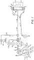
- Figure 1 shows a schematic diagram of the fluid delivery system with rapid melt switching capability of the present invention.
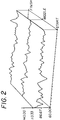
- Figure 2 shows the average laydown using the balloon method to supply coating to the hopper.
- Figure 3 shows the average coating laydown using piston pumps.
- the present invention is a method which allows a coating operator to switch from one melt to the next without introducing air into the delivery system. In addition, cross-contamination from one melt to the next is minimized.
- the system used in the present invention is shown in Figure 1.
- Two so-called "suck wands" 11 are used alternately to draw in a coating composition.
- the coating composition is held in vessels 12. While one wand is sucking in the coating composition, the other wand is being washed in the suck wand wash station shown as 13 in Figure 1.
- the inside of the wand is simultaneously flushed with water or gel solution.
- Each wand 11 is moved by pneumatic cylinders between either the wash station or the coating composition.
- Vessels 12 are held at 40°C and magnetically stirred during coating.
- Microswitch or IR sensors are used in the system to insure that a vessel 12 is present before the suck wand 11 is inserted.
- the system accommodates most types of vessels. After coating, the vessels are pushed into a plastic bag for delivery to a building washing machine (not shown). Alternatively, the vessels can be dumped and washed prior to being pushed into a plastic bag.
- the coating composition from vessel 12 is pumped through pump P1 and delivered to the hopper 30 at the normal coating flow rate, of for example 30 cc/min.
- pumps P3 and P4 which are connected to hardener vessels and other additive vessels, i.e. chemical addenda, are not active.
- the coating composition delivered to the hopper 30 is then applied to the web 31.
- valves V5 and V6 are closed and all of the coating composition delivered to the hopper 30 is subsequently coated on the web 31.
- pump P1A starts pumping at a rate of, for example, 200 cc/min.
- Pump P1 is switched to the next coating composition and continues pumping at 30 cc/min.
- the total flow going into the hopper then becomes 230 cc/min, as pump P1 has not stopped pumping or changed speed.
- Valves V5 and V6 are opened when pump 1A begins pumping.
- Pump 2 is started simultaneously with pump 1A. The result is that 200 cc/min is sucked out the ends of the hopper while 30 cc/min continues to be delivered to the web. Therefore, the bead is never broken. No human intervention is required.
- pump P1A stops valves V5 and V6 close off and pump P2 continues to pump flush water to drain at a slow rate. Pump P1 never changes speed through all of these sequences. It continues to deliver the normal coating flow.
- pumps P3 and P4 When pumps P3 and P4 are used with this system, their flow during purging will be maintained at a constant ratio to the stream being delivered by pumps P1 and P1A.
- the purge volume is conveniently expressed in terms of system volumes.
- One system volume is the volume of the tubing, the pump, the valves, the mixer and the hopper. This is defined as the volume of the inlet means and the volume of the hopper.
- Usually an acceptable purge can be achieved by passing three system volumes through the hopper.
- the system as shown in Figure 1 is controlled by a computer control system (not shown). All the timing, valve switching and calibration functions are controlled by the computer control system.
- all of the components, both computer and pumps reside on a portable cart. This portability yields two important benefits. It facilitates delivery system construction without disrupting ongoing coating operations and it allows the system to be tested on a variety of coating machines.
- the operator enters the aim flow rate (cc/min), the number of coatings in the experiment, the number of "good" feet of the coating he wants to produce, etc. After these parameters are entered, the operator initiates the system and feeds the melt vessels to the delivery system and applies labels to the web when prompted by the computer controls. The hopper remains in the coating position at all times.
- Figure 1 also includes a calibration line 21 leading to a weigh station 22 for calibrating pumps P1, P1-A, P3 and P4.
- calibration valve V7 directs flow through line 21 to the weigh station 22.
- the pumps can be calibrated with this configuration.
- the pumps, P1, P1A, P2, P3, P4 used are reciprocating piston pumps manufactured by Fluid Metering Inc. These pumps use ceramic pistons inside of ceramic cylinders and have dialable strokes. The pump sizes available have strokes of .01 to .05 cc/revolution, .01 to .10 cc/revolution and .02 to .32 cc/revolution. These pumps deliver linear fluid flow over the range of 0 to 2500 rpm and are rated to 100 psi.
- the stepper motors used to control the pumps are available from Seiberco Motors.
- the pump motor combination was tested over the 50 to 2500 rpm range. It was found to have a standard fluid delivery error of approximately ⁇ 0.2%. Although these were the pumps used with the present system, other pumps and motors can be substituted.
- the mixing chamber 23 used is a visco-coupled mixer element that operates at approximately 800 rpm.
- One of the concerns in the present system was the use of reciprocating piston pumps. The concern was that cross-lines might appear on the coating. The tests run have shown that cross-lines disappear when the single stroke volumes are small and the stroke frequency is high. In tests using the pumps of the present invention, cross-lines disappeared when the pulse frequency was above approximately 275 pulses/min. This corresponds to a 10 cc/ft2 laydown at 30 ft/min web speed. The example below gives the predicted cross-line intervals for three cases. The objective was to make a 4 inch wide coating at three web speeds, 10, 30 and 90 ft/min. One pump was used to deliver the total flow.
- CASE 1 Web speed 10 fpm Wet laydown 10 cc/ft2 Required flow rate 33.33 cc/min.
- FMI pump head is dialed to deliver 0.01333 cc/rev.
- Pump speed 2500 rpm Predicted cross-line interval 0.048 inches
- CASE 2 Web speed 30 fpm Wet laydown 8 cc/ft2 Required flow rate 80.0 cc/min.
- FMI pump head is dialed to deliver 0.032 cc/rev.
- Pump speed 2500 rpm Predicted cross-line interval 0.144 inches
- CASE 3 Web speed 90 fpm Wet laydown 6 cc/ft2 Required flow rate 180 cc/min.
- FMI pump head is dialed to deliver 0.072 cc/rev.
- Pump speed 2500 rpm Predicted cross-line interval 0.432 inches
- FIG 2 Shown in Figure 2 is the average laydown of a coating when using conventional (balloon method) pumps. This is compared with the piston pump method of the present invention which is shown in Figure 3. As can be seen from a comparison of Figures 2 and 3, significantly improved fluid delivery precision was achieved. In addition, no cross-lines were detected and rapid melt changeovers were achieved while the coating bead was essentially undisturbed during the purging operation.
- Table I Shown in Table I is a predicted increase in productivity when using the present invention. Examples 1 through 5 show the number of feet of a good coating required, the number of coatings produced per hour using conventional methods and the coatings per hour and percent productivity gain that can occur using the method of the present invention. As can be seen from Table I, productivity increases of 200 to 1200% are possible when using the method of the present invention. TABLE I Tubing I.D. 0.125 Inches Tubing I.D.
- Ex. 1-3 had web speed of 10 ft/min, wet coverage of 10 cc/ft2.
- Ex. 4 had web speed of 30 ft/min, wet coverage of 8 cc/ft2.
Landscapes
- Chemical & Material Sciences (AREA)
- Engineering & Computer Science (AREA)
- Materials Engineering (AREA)
- Physics & Mathematics (AREA)
- General Physics & Mathematics (AREA)
- Application Of Or Painting With Fluid Materials (AREA)
- Coating Apparatus (AREA)
Applications Claiming Priority (2)
| Application Number | Priority Date | Filing Date | Title |
|---|---|---|---|
| US976223 | 1992-11-13 | ||
| US07/976,223 US5306528A (en) | 1992-11-13 | 1992-11-13 | Precision fluid delivery system with rapid switching capability |
Publications (2)
| Publication Number | Publication Date |
|---|---|
| EP0598669A1 true EP0598669A1 (de) | 1994-05-25 |
| EP0598669B1 EP0598669B1 (de) | 1999-05-12 |
Family
ID=25523885
Family Applications (1)
| Application Number | Title | Priority Date | Filing Date |
|---|---|---|---|
| EP93420421A Expired - Lifetime EP0598669B1 (de) | 1992-11-13 | 1993-10-27 | Präzisionsvorrichtung zum Abgeben von Flüssigkeiten mit schnellem Schmelzschaltsystem |
Country Status (4)
| Country | Link |
|---|---|
| US (1) | US5306528A (de) |
| EP (1) | EP0598669B1 (de) |
| JP (1) | JPH06206039A (de) |
| DE (1) | DE69324887T2 (de) |
Families Citing this family (6)
| Publication number | Priority date | Publication date | Assignee | Title |
|---|---|---|---|---|
| US5432022A (en) * | 1993-11-12 | 1995-07-11 | Dreisbach Electromotive Inc. | Coated cathode for rechargeable metal battery |
| TWI242472B (en) * | 2004-07-02 | 2005-11-01 | Hannstar Display Corp | Apparatus and method for processing a substrate |
| US20110014391A1 (en) * | 2008-03-26 | 2011-01-20 | Yapel Robert A | Methods of slide coating two or more fluids |
| US20110059249A1 (en) * | 2008-03-26 | 2011-03-10 | 3M Innovative Properties Company | Methods of slide coating two or more fluids |
| BRPI0910275A2 (pt) * | 2008-03-26 | 2015-09-29 | 3M Innovative Properties Co | métodos de aplicação de fluidos como um revestimento de deslizamento contendo precursores poliméricos de múltiplas unidades |
| US10300504B2 (en) | 2013-07-19 | 2019-05-28 | Graco Minnesota Inc. | Spray system pump wash sequence |
Citations (4)
| Publication number | Priority date | Publication date | Assignee | Title |
|---|---|---|---|---|
| US2529937A (en) * | 1944-09-02 | 1950-11-14 | Eastman Kodak Co | Liquid metering device |
| US4002269A (en) * | 1974-08-16 | 1977-01-11 | Technicon Instruments Corporation | Liquid proportioning system in a liquid sample analyzer |
| JPS54116294A (en) * | 1978-03-01 | 1979-09-10 | Hitachi Ltd | Analytical meter |
| US4362122A (en) * | 1981-05-04 | 1982-12-07 | Polaroid Corporation | Fluid dispensing system |
Family Cites Families (28)
| Publication number | Priority date | Publication date | Assignee | Title |
|---|---|---|---|---|
| US2795206A (en) * | 1955-04-28 | 1957-06-11 | Conforming Matrix Corp | Automatic spray painting apparatus |
| US3166438A (en) * | 1960-11-23 | 1965-01-19 | Gen Motors Corp | Electrostatic painting apparatus |
| US3145930A (en) * | 1961-01-05 | 1964-08-25 | Metallgesellschaft Ag | Electrostatic paint spraying apparatus for changing liquids |
| US3205853A (en) * | 1962-01-12 | 1965-09-14 | Gen Motors Corp | Electrostatic painting apparatus |
| US3348774A (en) * | 1965-03-18 | 1967-10-24 | Gyromat Corp | Semi-automatic color change system for paint spray installation |
| US3450092A (en) * | 1965-07-08 | 1969-06-17 | Vilbiss Co The De | Color change apparatus |
| US3477870A (en) * | 1966-03-03 | 1969-11-11 | Gen Motors Corp | Method of spray coating a series of articles including the application of different colors to different articles |
| US3385522A (en) * | 1966-05-20 | 1968-05-28 | Vilbiss Co | Cleaning device for liquid pressure regulating apparatus |
| US3637136A (en) * | 1970-03-11 | 1972-01-25 | Epec Systems Corp | Spray gun system for slurry |
| US3674207A (en) * | 1970-11-06 | 1972-07-04 | Emidio J Carbonetti Jr | Automated paint spray system |
| CH585920A5 (de) * | 1974-06-07 | 1977-03-15 | Hoechst Ag | |
| US4050410A (en) * | 1974-06-07 | 1977-09-27 | Hoechst Aktiengesellschaft | Apparatus for the manufacture of a series of photoconductor webs |
| US4038442A (en) * | 1975-09-16 | 1977-07-26 | Fuji Photo Film Co., Ltd. | Method for coating |
| JPS58907B2 (ja) * | 1979-06-13 | 1983-01-08 | コニカ株式会社 | 基体の塗布方法およびホッパ−装置 |
| US4337282A (en) * | 1980-08-12 | 1982-06-29 | Binks Manufacturing Co. | Color change system for spray coating apparatus |
| US4375865A (en) * | 1980-08-12 | 1983-03-08 | Binks Manufacturing Company | Color change system for spray coating apparatus |
| US4592305A (en) * | 1981-01-26 | 1986-06-03 | Ransburg Corporation | Variable low-pressure fluid color change cycle |
| US4457258A (en) * | 1983-01-04 | 1984-07-03 | Cocks Eric H | Marking apparatus for paints and inks |
| JPS6064662A (ja) * | 1983-09-19 | 1985-04-13 | Fuji Photo Film Co Ltd | 塗布方法 |
| US4555416A (en) * | 1984-08-27 | 1985-11-26 | Ball Corporation | Spray apparatus with self cleaning nozzle |
| US4704296A (en) * | 1984-09-28 | 1987-11-03 | Magna-Graphics Corporation | Web coating method and apparatus |
| DE3440381A1 (de) * | 1984-11-05 | 1986-05-07 | Ransburg Gmbh, 6056 Heusenstamm | Verfahren und vorrichtung zum automatischen elektrostatischen spruehbeschichten |
| JPS62215948A (ja) * | 1986-03-18 | 1987-09-22 | Konishiroku Photo Ind Co Ltd | 歩留りを向上させる連続塗布方法 |
| US4881563A (en) * | 1986-09-05 | 1989-11-21 | General Motors Corporation | Paint color change system |
| EP0303541B1 (de) * | 1987-08-14 | 1991-10-09 | Sames S.A. | Farbspritzanlage für Beschichtungsprodukte, zum Beispiel für wasserlösliche Farbe |
| US4830887A (en) * | 1988-04-22 | 1989-05-16 | Eastman Kodak Company | Curtain coating method and apparatus |
| JP2520720B2 (ja) * | 1989-03-16 | 1996-07-31 | 富士写真フイルム株式会社 | 塗布方法 |
| US4979380A (en) * | 1989-09-12 | 1990-12-25 | Sakowski And Robbins Corporation | Automated dye pattern application system |
-
1992
- 1992-11-13 US US07/976,223 patent/US5306528A/en not_active Expired - Fee Related
-
1993
- 1993-10-27 EP EP93420421A patent/EP0598669B1/de not_active Expired - Lifetime
- 1993-10-27 DE DE69324887T patent/DE69324887T2/de not_active Expired - Fee Related
- 1993-11-11 JP JP5282496A patent/JPH06206039A/ja active Pending
Patent Citations (4)
| Publication number | Priority date | Publication date | Assignee | Title |
|---|---|---|---|---|
| US2529937A (en) * | 1944-09-02 | 1950-11-14 | Eastman Kodak Co | Liquid metering device |
| US4002269A (en) * | 1974-08-16 | 1977-01-11 | Technicon Instruments Corporation | Liquid proportioning system in a liquid sample analyzer |
| JPS54116294A (en) * | 1978-03-01 | 1979-09-10 | Hitachi Ltd | Analytical meter |
| US4362122A (en) * | 1981-05-04 | 1982-12-07 | Polaroid Corporation | Fluid dispensing system |
Non-Patent Citations (1)
| Title |
|---|
| PATENT ABSTRACTS OF JAPAN vol. 3, no. 139 (E - 152) 17 November 1979 (1979-11-17) * |
Also Published As
| Publication number | Publication date |
|---|---|
| DE69324887D1 (de) | 1999-06-17 |
| EP0598669B1 (de) | 1999-05-12 |
| DE69324887T2 (de) | 1999-11-11 |
| US5306528A (en) | 1994-04-26 |
| JPH06206039A (ja) | 1994-07-26 |
Similar Documents
| Publication | Publication Date | Title |
|---|---|---|
| KR101231945B1 (ko) | 가변 홈 위치 토출 장치용 시스템 및 방법 | |
| KR100560257B1 (ko) | 도포장치및도포방법 | |
| JP3333121B2 (ja) | 塗布装置 | |
| EP0598669A1 (de) | Präzisionsvorrichtung zum Abgeben von Flüssigkeiten mit schnellem Schmelzschaltsystem | |
| EP0515671B1 (de) | Misch- und abgabevorrichtung für flüssigkeiten | |
| JPH0727150U (ja) | シリカ系被膜形成用塗布液吐出装置 | |
| WO2003079000A1 (fr) | Systeme de pompe de dosage de liquide a gradient, et chromatographe en phase liquide | |
| JPH09264888A (ja) | 液体クロマトグラフ | |
| JP4366757B2 (ja) | 塗布装置、塗布方法ならびにプラズマディスプレイまたはディスプレイ用部材の製造方法 | |
| TW200417418A (en) | Substrate processing device and liquid feeding device | |
| JPH05157743A (ja) | 液体クロマトグラフ | |
| JP3117623B2 (ja) | 複数種流体混合ポンプ装置 | |
| EP1404463A2 (de) | Verfahren und vorrichtung zur reinigung von halbleiterwafern und anderen flachen medien | |
| JPH0777521A (ja) | 液体クロマトグラフ | |
| JP2002174167A (ja) | 高粘度流体の送液装置 | |
| JP2504001B2 (ja) | 送液装置 | |
| JPH06216017A (ja) | レジスト塗布装置 | |
| JPH03152A (ja) | 塗布装置 | |
| JPH0439034B2 (de) | ||
| JPH1150967A (ja) | ポンプ装置及びその制御方法並びにその制御プログラムを記録した記録媒体 | |
| JP2000343015A (ja) | 塗布装置 | |
| JP3385563B2 (ja) | 塗料供給装置および塗料供給方法 | |
| JPH0624657B2 (ja) | 多色塗装装置 | |
| JPH02174972A (ja) | ホース内残存塗料の有効使用量測定方法 | |
| GB2175278A (en) | Avoiding drips in liquid dispensing |
Legal Events
| Date | Code | Title | Description |
|---|---|---|---|
| PUAI | Public reference made under article 153(3) epc to a published international application that has entered the european phase |
Free format text: ORIGINAL CODE: 0009012 |
|
| AK | Designated contracting states |
Kind code of ref document: A1 Designated state(s): BE DE FR GB NL |
|
| 17P | Request for examination filed |
Effective date: 19941027 |
|
| 17Q | First examination report despatched |
Effective date: 19970929 |
|
| GRAG | Despatch of communication of intention to grant |
Free format text: ORIGINAL CODE: EPIDOS AGRA |
|
| GRAG | Despatch of communication of intention to grant |
Free format text: ORIGINAL CODE: EPIDOS AGRA |
|
| GRAH | Despatch of communication of intention to grant a patent |
Free format text: ORIGINAL CODE: EPIDOS IGRA |
|
| GRAH | Despatch of communication of intention to grant a patent |
Free format text: ORIGINAL CODE: EPIDOS IGRA |
|
| GRAA | (expected) grant |
Free format text: ORIGINAL CODE: 0009210 |
|
| AK | Designated contracting states |
Kind code of ref document: B1 Designated state(s): BE DE FR GB NL |
|
| REF | Corresponds to: |
Ref document number: 69324887 Country of ref document: DE Date of ref document: 19990617 |
|
| ET | Fr: translation filed | ||
| PLBE | No opposition filed within time limit |
Free format text: ORIGINAL CODE: 0009261 |
|
| STAA | Information on the status of an ep patent application or granted ep patent |
Free format text: STATUS: NO OPPOSITION FILED WITHIN TIME LIMIT |
|
| 26N | No opposition filed | ||
| PGFP | Annual fee paid to national office [announced via postgrant information from national office to epo] |
Ref country code: GB Payment date: 20000918 Year of fee payment: 8 |
|
| PGFP | Annual fee paid to national office [announced via postgrant information from national office to epo] |
Ref country code: NL Payment date: 20000929 Year of fee payment: 8 |
|
| PGFP | Annual fee paid to national office [announced via postgrant information from national office to epo] |
Ref country code: FR Payment date: 20001009 Year of fee payment: 8 |
|
| PGFP | Annual fee paid to national office [announced via postgrant information from national office to epo] |
Ref country code: DE Payment date: 20001030 Year of fee payment: 8 |
|
| PGFP | Annual fee paid to national office [announced via postgrant information from national office to epo] |
Ref country code: BE Payment date: 20001120 Year of fee payment: 8 |
|
| PG25 | Lapsed in a contracting state [announced via postgrant information from national office to epo] |
Ref country code: GB Free format text: LAPSE BECAUSE OF NON-PAYMENT OF DUE FEES Effective date: 20011027 |
|
| PG25 | Lapsed in a contracting state [announced via postgrant information from national office to epo] |
Ref country code: BE Free format text: LAPSE BECAUSE OF NON-PAYMENT OF DUE FEES Effective date: 20011031 |
|
| REG | Reference to a national code |
Ref country code: GB Ref legal event code: IF02 |
|
| BERE | Be: lapsed |
Owner name: EASTMAN KODAK CY Effective date: 20011031 |
|
| PG25 | Lapsed in a contracting state [announced via postgrant information from national office to epo] |
Ref country code: NL Free format text: LAPSE BECAUSE OF NON-PAYMENT OF DUE FEES Effective date: 20020501 |
|
| GBPC | Gb: european patent ceased through non-payment of renewal fee |
Effective date: 20011027 |
|
| PG25 | Lapsed in a contracting state [announced via postgrant information from national office to epo] |
Ref country code: FR Free format text: LAPSE BECAUSE OF NON-PAYMENT OF DUE FEES Effective date: 20020628 |
|
| NLV4 | Nl: lapsed or anulled due to non-payment of the annual fee |
Effective date: 20020501 |
|
| PG25 | Lapsed in a contracting state [announced via postgrant information from national office to epo] |
Ref country code: DE Free format text: LAPSE BECAUSE OF NON-PAYMENT OF DUE FEES Effective date: 20020702 |
|
| REG | Reference to a national code |
Ref country code: FR Ref legal event code: ST |