EP0593934B1 - Haltevorrichtung für ein elektrisches Gerät - Google Patents
Haltevorrichtung für ein elektrisches Gerät Download PDFInfo
- Publication number
- EP0593934B1 EP0593934B1 EP93115405A EP93115405A EP0593934B1 EP 0593934 B1 EP0593934 B1 EP 0593934B1 EP 93115405 A EP93115405 A EP 93115405A EP 93115405 A EP93115405 A EP 93115405A EP 0593934 B1 EP0593934 B1 EP 0593934B1
- Authority
- EP
- European Patent Office
- Prior art keywords
- holding device
- clamping
- lever
- electrical apparatus
- limbs
- Prior art date
- Legal status (The legal status is an assumption and is not a legal conclusion. Google has not performed a legal analysis and makes no representation as to the accuracy of the status listed.)
- Expired - Lifetime
Links
- 239000000470 constituent Substances 0.000 claims 1
- 230000000284 resting effect Effects 0.000 description 1
- 230000000717 retained effect Effects 0.000 description 1
- 238000010079 rubber tapping Methods 0.000 description 1
Images

Classifications
-
- F—MECHANICAL ENGINEERING; LIGHTING; HEATING; WEAPONS; BLASTING
- F16—ENGINEERING ELEMENTS AND UNITS; GENERAL MEASURES FOR PRODUCING AND MAINTAINING EFFECTIVE FUNCTIONING OF MACHINES OR INSTALLATIONS; THERMAL INSULATION IN GENERAL
- F16M—FRAMES, CASINGS OR BEDS OF ENGINES, MACHINES OR APPARATUS, NOT SPECIFIC TO ENGINES, MACHINES OR APPARATUS PROVIDED FOR ELSEWHERE; STANDS; SUPPORTS
- F16M13/00—Other supports for positioning apparatus or articles; Means for steadying hand-held apparatus or articles
- F16M13/02—Other supports for positioning apparatus or articles; Means for steadying hand-held apparatus or articles for supporting on, or attaching to, an object, e.g. tree, gate, window-frame, cycle
-
- B—PERFORMING OPERATIONS; TRANSPORTING
- B60—VEHICLES IN GENERAL
- B60R—VEHICLES, VEHICLE FITTINGS, OR VEHICLE PARTS, NOT OTHERWISE PROVIDED FOR
- B60R11/00—Arrangements for holding or mounting articles, not otherwise provided for
- B60R11/02—Arrangements for holding or mounting articles, not otherwise provided for for radio sets, television sets, telephones, or the like; Arrangement of controls thereof
- B60R11/0241—Arrangements for holding or mounting articles, not otherwise provided for for radio sets, television sets, telephones, or the like; Arrangement of controls thereof for telephones
-
- F—MECHANICAL ENGINEERING; LIGHTING; HEATING; WEAPONS; BLASTING
- F16—ENGINEERING ELEMENTS AND UNITS; GENERAL MEASURES FOR PRODUCING AND MAINTAINING EFFECTIVE FUNCTIONING OF MACHINES OR INSTALLATIONS; THERMAL INSULATION IN GENERAL
- F16M—FRAMES, CASINGS OR BEDS OF ENGINES, MACHINES OR APPARATUS, NOT SPECIFIC TO ENGINES, MACHINES OR APPARATUS PROVIDED FOR ELSEWHERE; STANDS; SUPPORTS
- F16M11/00—Stands or trestles as supports for apparatus or articles placed thereon ; Stands for scientific apparatus such as gravitational force meters
- F16M11/02—Heads
- F16M11/04—Means for attachment of apparatus; Means allowing adjustment of the apparatus relatively to the stand
- F16M11/041—Allowing quick release of the apparatus
-
- F—MECHANICAL ENGINEERING; LIGHTING; HEATING; WEAPONS; BLASTING
- F16—ENGINEERING ELEMENTS AND UNITS; GENERAL MEASURES FOR PRODUCING AND MAINTAINING EFFECTIVE FUNCTIONING OF MACHINES OR INSTALLATIONS; THERMAL INSULATION IN GENERAL
- F16M—FRAMES, CASINGS OR BEDS OF ENGINES, MACHINES OR APPARATUS, NOT SPECIFIC TO ENGINES, MACHINES OR APPARATUS PROVIDED FOR ELSEWHERE; STANDS; SUPPORTS
- F16M13/00—Other supports for positioning apparatus or articles; Means for steadying hand-held apparatus or articles
-
- H—ELECTRICITY
- H04—ELECTRIC COMMUNICATION TECHNIQUE
- H04M—TELEPHONIC COMMUNICATION
- H04M1/00—Substation equipment, e.g. for use by subscribers
- H04M1/02—Constructional features of telephone sets
- H04M1/0297—Telephone sets adapted to be mounted on a desk or on a wall
-
- B—PERFORMING OPERATIONS; TRANSPORTING
- B60—VEHICLES IN GENERAL
- B60R—VEHICLES, VEHICLE FITTINGS, OR VEHICLE PARTS, NOT OTHERWISE PROVIDED FOR
- B60R11/00—Arrangements for holding or mounting articles, not otherwise provided for
- B60R2011/0042—Arrangements for holding or mounting articles, not otherwise provided for characterised by mounting means
- B60R2011/0049—Arrangements for holding or mounting articles, not otherwise provided for characterised by mounting means for non integrated articles
- B60R2011/0064—Connection with the article
- B60R2011/0071—Connection with the article using latches, clips, clamps, straps or the like
Definitions
- the invention is based on a holding device according to the preamble of claim 1.
- a holding device is known (DE-GM 89 01 019), which requires an electrical device which has a groove on two opposite end faces into which a strip-shaped projection and a resilient pawl of the holding device engage.
- the electrical device In the known holding device, the electrical device must first be inserted obliquely onto the strip-shaped projection and then lowered until the resilient pawl engages in the corresponding groove of the electrical device.
- the invention has for its object to develop the holding device such that the attachment of the electrical device, which is preferably a cuboid radio, is simplified for the user.
- the holding device has the advantage that the electrical device only needs to be placed on the holding device and then a lever has to be pivoted. It is therefore not necessary to thread the electrical device.
- this has an angled device part at the end opposite the sliding slide, which part contains a clamping mechanism for releasably holding a device placed on the electrical device. If the electrical device is a radio telephone with a base part and a handset, the handset placed on the base part is held by the clamping mechanism when the base part is inserted into the holding device. Further advantageous embodiments of the invention result from the other subclaims.
- 10 means an L-shaped holding device for a cuboid electrical device, which is preferably a radio telephone, which must be detachably but securely fastened in a vehicle.
- the holding device 10 has a flat, box-shaped lower part 11 which is open at the bottom and merges at one end into an angled part 12.
- Two spaced-apart U-shaped slots 13, 14 in the lower part 11 release a U-shaped pressure piece 15.
- This is interrupted, so that the pressure piece 15 is connected to the lower part 11 at this point.
- the parallel legs 17, 18 of the pressure piece 15 can be moved somewhat transversely to the longitudinal direction of the holding device 10 due to the slots 13, 14.
- the legs 17, 18 and the grooves 45, 46 have a dovetail cross section.
- a flat locking lever 21 pivotably mounted in the wall of the lower part 11 has a two-armed clamping part 22 with flattened portions 23, 24 at the ends and with a lever arm 25, the free end 26 of which is movably mounted in a recess 27 of a slide slide 28.
- the slide valve 28 carries a projection 30 which projects outwards through a longitudinal slot in the lower part 20.
- the slide valve 28 is guided through a guide slot 31 and two parallel guide ribs 32 in the housing wall.
- Four holes 33 are provided for screws 34 which are screwed into corresponding holes in a wall 35.
- the screws 34 are preferably self-tapping.
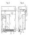
- the radio telephone 40 (see FIGS. 3 and 4) which can be detachably fastened with the holding device 10 consists of a cuboid base part 41 with a recess 42 on the top 43 and a handset 44 (FIG. 4) which are placed in the recess 42 can.
- the angled part 12 of the holding device 10 is designed as a hollow body and, as shown in FIG. 2, contains a clamping mechanism 50 which consists of a two-armed pivoting lever 52 which can be pivoted about a shaft 51 and a clamping lever 53 which is pivotably connected to the pivoting lever 52.
- a free end 54 of the pivot lever 52 protrudes from a first opening 55 and the clamping lever 53 min its free end 56 from a second opening 57.
- the free end 56 of the clamping lever 53 has a clamping piece 58 on its side facing the lower part 11, which is preferably spherical.
- the base part 41 of the radio telephone 40 to be fastened is placed on the holding device 10 fastened to the wall 35 with the screws 34, the parallel legs 17, 18 (FIGS. 1 and 5) engaging in the parallel grooves 45, 46 of the base part 41.
- the clamping device 50 (FIG. 2) takes its basic position - cf. Solid lines in Fig. 2 - a, in which the free end 54 of the pivot lever 52 from the protrudes first opening 55. If the radio telephone is then pushed in the direction of the arrow P2 (FIG. 3), it moves the swivel lever 52 with its front end face into the position indicated by dashed lines in FIG.
- the base part 41 of the radio telephone 40 comes under the projecting part 36 of the angled part 12 (cf. FIG. 4).
- the extension 30 of the slide valve 28 is then pushed in the direction of arrow P1 until it assumes the clamping position shown in FIG. 5.
- the lever arm 25 is pivoted in such a way that the flats 23 of the clamping lever 22 press the parallel legs 17, 18 of the holding device 10 outwards, until the clamping part 22 snaps into a position in which the flats are approximately parallel to the Legs 17 and 18 stand. This forms a latching position in which the base part 41 of the radio telephone 40 is clamped on the lower part 11; see. 5 and 7.
- the extension 30 (FIG. 5) is moved in the direction of the arrow P3 until it again assumes the position shown in FIG. 1. Then the radio telephone 40 can be conveniently pulled out of the holding device 10 because the clamping lever 53 yields somewhat due to its elasticity.
- a spring element (not shown in the drawing) in the angled part 12 ensures that the clamping device 50 returns to the basic position shown by solid lines in FIG. 2.
Landscapes
- Engineering & Computer Science (AREA)
- General Engineering & Computer Science (AREA)
- Mechanical Engineering (AREA)
- Signal Processing (AREA)
- Telephone Set Structure (AREA)
- Fittings On The Vehicle Exterior For Carrying Loads, And Devices For Holding Or Mounting Articles (AREA)
Description
- Die Erfindung geht von einer Haltevorrichtung nach dem Oberbegriff des Anspruchs 1 aus.
- Es ist eine Haltevorrichtung bekannt (DE-GM 89 01 019), die ein elektrisches Gerät voraussetzt, das an Zwei gegenüberliegenden Stirnseiten eine Nut aufweist, in die ein leistenförmiger Vorsprung und eine federnde Klinke der Haltevorrichtung eingreifen. Bei der bekannten Haltevorrichtung muß das elektrische Gerät erst schräg auf den leistenförmigen Vorsprung gesteckt und dann abgesenkt werden, bis die federnde Klinke in die entsprechende Nut des elektrischen Gerätes einrastet.
- Der Erfindung liegt die Aufgabe zugrunde, die Haltevorrichtung derart weiterzubilden, daß das Befestigen des elektrischen Gerätes, das ist vorzugsweise ein quaderförmiges Funkgerät, für den Benutzer vereinfacht wird.
- Diese Aufgabe wird durch die in dem Anspruch 1 angegebenen Merkmale gelöst. Mit der Haltevorrichtung ist der Vorteil verbunden, daß das elektrische Gerät lediglich auf die Haltevorrichtung gelegt zu werden braucht und anschließend ein Hebel geschwenkt werden muß. Ein Einfädeln des elektrischen Gerätes ist somit nicht erforderlich. In einer bevorzugten Ausführung der erfindungsgemäßen Haltevorrichtung weist diese an dem dem Gleitschieber gegenüberliegenden Ende einen abgewinkelten Geräteteil auf, der einen Klemmechanismus zum lösbaren Festhalten einer auf dem elektrischen Gerät abgelegten Vorrichtung enthält. Ist das elektrische Gerät ein Funktelefon mit einem Basisteil und einem Handapparat, dann wird der auf dem Basisteil abgelegte Handapparat beim Einschieben des Basisteils in die Haltevorrichtung durch den Klemmechanismus festgehalten. Weitere vorteilhafte Ausgestaltungen der Erfindung ergeben sich aus den anderen Unteransprüchen.
- In der Zeichnung ist die Erfindung anhand mehrerer Figuren dargestellt und wird im folgenden näher erläutert. Es zeigen
- Fig. 1 eine Draufsicht auf die Haltevorrichtung,
- Fig. 2 eine Seitenansicht zu Fig. 1, teilweise im Schnitt,
- Fig. 3 eine Draufsicht der Haltevorrichtung nach Fig. 1 mit aufgelegtem elektrischen Gerät,
- Fig. 4 eine Seitenansicht zu Fig. 3,
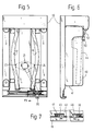
- Fig. 5 eine Draufsicht der Haltevorrichtung bei in Arbeitsstellung befindlichem Schwenkhebel,
- Fig. 6 eine Seitenansicht zu Fig. 5 mit durch die Haltevorrichtung festgehaltenem Basisteil und Handapparat eines Funktelefons und
- Fig. 7 eine schematische Darstellung des auf der Haltevorrichtung festgeklemmten elektrischen Gerätes.
- In den Fig. 1 und 2 bedeutet 10 eine L-förmige Haltevorrichtung für ein quaderförmiges elektrisches Gerät, das ist vorzugsweise ein Funktelefon, welches in einem Fahrzeug lösbar, jedoch rüttelsicher befestigt werden muß. Die Haltevorrichtung 10 weist ein flaches, kastenförmiges, unten offenes Unterteil 11 auf, das an einem Ende in einen abgewinkelten Teil 12 übergeht. Zwei einen Abstand voneinander aufweisende U-förmige Schlitze 13, 14 im Unterteil 11 geben ein U-förmiges Druckstück 15 frei. In einem Bereich 16 am halbkreisförmigen Teil des Schlitzes 14 ist dieser unterbrochen, so daß das Druckstück 15 an dieser Stelle mit dem Unterteil 11 verbunden ist. Die parallelen Schenkel 17, 18 des Druckstücks 15 sind infolge der Schlitze 13, 14 etwas quer zur Längsrichtung der Haltevorrichtung 10 bewegbar. Sie stehen außerdem über der Oberfläche der Wand 20 hervor und greifen in entsprechende parallele Nuten 45, 46 (Fig. 7) an der Unterseite des auf dem Unterteil 11 ruhenden elektrischen Gerätes 40 ein. Die Schenkel 17, 18 und die Nuten 45, 46 haben einen schwalbenschwanzförmigen Querschnitt.
- Ein in der Wand des Unterteils 11 schwenkbar gelagerter flacher Rasthebel 21 weist ein zweiarmiges Klemmteil 22 mit Abflachungen 23, 24 an den Enden und mit einem Hebelarm 25 auf, dessen freies Ende 26 in einer Ausnehmung 27 eines Gleitschiebers 28 beweglich gelagert ist. Der Gleitschieber 28 trägt einen Ansatz 30, der durch einen Längsschlitz des Unterteils 20 nach außen ragt. Der Gleitschieber 28 wird durch einen Führungsschlitz 31 und zwei dazu parallele Führungsrippen 32 in der Gehäusewand geführt. Vier Löcher 33 sind für Schrauben 34 vorgesehen, die in entsprechende Löcher einer Wand 35 eingeschraubt sind. Die Schrauben 34 sind vorzugsweise selbstschneidend.
- Das mit der Haltevorrichtung 10 lösbar zu befestigende Funktelefon 40 (vgl. Fig. 3 und 4) besteht aus einem quaderförmigen Basisteil 41 mit einer Mulde 42 an der Oberseite 43 und einen Handapparat 44 (Fig. 4), der in die Mulde 42 gelegt werden kann.
- Der abgewinkelte Teil 12 der Haltevorrichtung 10 ist als Hohlkörper ausgebildet und enthält, wie in Fig. 2 gezeigt, einen Klemmechanismus 50, der aus einem zweiarmigen, um eine Welle 51 schwenkbaren Schwenkhebel 52 und einem mit dem Schwenkhebel 52 schwenkbar verbundenen Klemmhebel 53 besteht. Ein freies Ende 54 des Schwenkhebels 52 ragt aus einer ersten Öffnung 55 und der Klemmhebel 53 min seinem freien Ende 56 aus einer zweiten Öffnung 57 hervor. Das freie Ende 56 des Klemmhebels 53 weist auf seiner dem Unterteil 11 zugewandten Seite ein Klemmstück 58 auf, das vorzugsweise ballig ausgebildet ist.
- Die Wirkungsweise der vorstehend beschriebenen Haltevorrichtung ist folgende.
- Auf die mit den Schrauben 34 an der Wand 35 befestigte Haltevorrichtung 10 wird das Basisteil 41 des zu befestigenden Funktelefons 40 gelegt, wobei die parallelen Schenkel 17, 18 (Fig. 1 und 5) in die parallelen Nuten 45, 46 des Basisteils 41 eingreifen. Die Klemmvorrichtung 50 (Fig. 2) nimmt dabei ihre Grundstellung - vgl. ausgezogene Linien in Fig. 2 - ein, in welcher das freie Ende 54 des Schwenkhebels 52 aus der ersten Öffnung 55 hervorsteht. Wird dann das Funktelefon in Pfeilrichtung P2 (Fig. 3) geschoben, so bewegt es mit seiner vorderen Stirnseite den Schwenkhebel 52 in die in Fig. 2 gestrichelt angedeutete Lage, wobei sich der Klemmhebel 53 weiter aus der zweiten Öffnung 57 hervorschiebt und in der Endstellung die in Fig. 6 gezeigte zweite Lage einnimmt, in der das freie Ende 56 des Klemmhebels 53 den Handapparat 44 in die Mulde 42 (Fig. 3) des Basisteils 41 drückt, so daß er auch bei Erschütterungen festgehalten wird.
- Gleichzeitig gelangt das Basisteil 41 des Funktelefons 40 unter den vorstehenden Teil 36 des abgewinkelten Teils 12 (vgl. Fig. 4). Anschließend wird der Ansatz 30 des Gleitschiebers 28 in Pfeilrichtung P1 geschoben, bis er die in Fig. 5 gezeigte Klemmstellung einnimmt. Dabei wird der Hebelarm 25 derart geschwenkt, daß die Abflachungen 23 des Klemmhebels 22 die parallelen Schenkel 17, 18 der Haltevorrichtung 10 nach außen drücken, und zwar so weit, bis das Klemmteil 22 in eine Lage schnappt, in welcher die Abflachungen etwa parallel zu den Schenkeln 17 und 18 stehen. Dadurch wird eine Raststellung gebildet, in welcher das Basisteil 41 des Funktelefons 40 auf dem Unterteil 11 festgeklemmt ist; vgl. Fig. 5 und 7.
- Zum Öffnen der Haltevorrichtung 10 wird der Ansatz 30 (Fig. 5) solange in Pfeilrichtung P3 bewegt, bis er wieder die in Fig. 1 gezeigte Lage einnimmt. Dann kann das Funktelefon 40 bequem aus der Haltevorrichtung 10 herausgezogen werden, weil der Klemmhebel 53 infolge seiner Elastizität etwas nachgibt. Ein in der Zeichnung nicht dargestelltes Federelement in dem abgewinkelten Teil 12 sorgt dafür, daß die Klemmvorrichtung 50 in die in Fig. 2 durch ausgezogene Linien dargestellte Grundstellung zurückkehrt.
Claims (6)
- Haltevorrichtung für ein an einer Wand zu befestigendes elektrisches Gerät, wobei die Haltevorrichtung ein Unterteil mit bewegbaren Haltemitteln aufweist, dadurch gekennzeichnet, daß die Haltemittel aus einem manuell schwenkbaren Rasthebel (21) und zwei parallelen Schenkeln (17, 18) eines elastischen Druckstücks (15) bestehen, daß die Schenkel (17, 18) in parallele Nuten (45, 46) an der Unterseite des elektrischen Gerätes (40) eingreifen und daß ein Klemmteil (22) des Rasthebels (21) bei in die Klemmstellung geschwenktem Rasthebel (21) die Schenkel (17, 18) auseinanderdrückt.
- Haltevorrichtung nach Anspruch 1, dadurch gekennzeichnet, daß das elastische Druckstück (15) Bestandteil des Unterteils (11) der aus einem Kunststoff bestehenden Haltevorrichtung (10) ist.
- Haltevorrichtung nach Anspruch 1 oder 2, dadurch gekennzeichnet, daß der Rasthebel (21) aus dem Klemmteil (22) und einem damit verbundenen Hebelarm (25) besteht, dessen freies Ende (26) in einem Gleitschieber (28) gelagert ist, der in Führungsmitteln (31) des Unterteils (11) von einer Grundstellung in eine Klemmstellung und umgekehrt verschiebbar ist.
- Haltevorrichtung nach einem der Ansprüche 1 bis 3, dadurch gekennzeichnet, daß das Klemmteil (22) an gegenüberliegenden Seiten je eine Abflachung (23, 24) aufweist, die in Verbindung mit den parallelen Schenkeln (17, 18) des Druckstücks (15) ein Rastmittel bildet.
- Haltevorrichtung nach einem der Ansprüche 3 oder 4, dadurch gekennzeichnet, daß die Haltevorrichtung (10) an dem dem Gleitschieber (28) gegenüberliegenden Ende einen abgewinkelten Teil (12) aufweist, der einen Klemmechanismus (50) zum lösbaren Festhalten einer auf dem elektrischen Gerät (40) abgelegten Vorrichtung (44) enthält.
- Haltevorrichtung nach Anspruch 5, dadurch gekennzeichnet, daß der Klemmechanismus (50) aus einem zweiarmigen Schwenkhebel (52) und einem damit schwenkbar verbundenen Klemmhebel (53) besteht.
Applications Claiming Priority (2)
| Application Number | Priority Date | Filing Date | Title |
|---|---|---|---|
| DE4235041A DE4235041A1 (de) | 1992-10-17 | 1992-10-17 | Haltevorrichtung für ein elektrisches Gerät |
| DE4235041 | 1992-10-17 |
Publications (2)
| Publication Number | Publication Date |
|---|---|
| EP0593934A1 EP0593934A1 (de) | 1994-04-27 |
| EP0593934B1 true EP0593934B1 (de) | 1996-04-24 |
Family
ID=6470697
Family Applications (1)
| Application Number | Title | Priority Date | Filing Date |
|---|---|---|---|
| EP93115405A Expired - Lifetime EP0593934B1 (de) | 1992-10-17 | 1993-09-24 | Haltevorrichtung für ein elektrisches Gerät |
Country Status (2)
| Country | Link |
|---|---|
| EP (1) | EP0593934B1 (de) |
| DE (2) | DE4235041A1 (de) |
Families Citing this family (3)
| Publication number | Priority date | Publication date | Assignee | Title |
|---|---|---|---|---|
| DE19509685A1 (de) * | 1995-03-07 | 1996-09-12 | Deutsche Telephonwerk Kabel | Kommunikationsendgerät für Bündelfunk |
| DE19624161C2 (de) * | 1996-06-18 | 2001-06-07 | Gerhard Mueller | Halteanordnung |
| CN114776997B (zh) * | 2022-03-23 | 2023-10-10 | 呼伦贝尔安泰热电有限责任公司海拉尔热电厂 | 一种电厂热控用热控仪表安装装置 |
Family Cites Families (5)
| Publication number | Priority date | Publication date | Assignee | Title |
|---|---|---|---|---|
| US4986503A (en) * | 1988-11-25 | 1991-01-22 | Kabat Thomas W | Mounting device |
| DE8901019U1 (de) * | 1989-01-31 | 1989-03-09 | Robert Bosch Gmbh, 7000 Stuttgart, De | |
| US5038253A (en) * | 1990-05-14 | 1991-08-06 | Motorola, Inc. | Transceiver mounting assembly having integrally formed lock |
| US5169097A (en) * | 1990-11-27 | 1992-12-08 | Oki Electric Industry Co., Ltd. | Apparatus and method for supporting an accessory unit within an automobile storage area |
| DE4107996C2 (de) * | 1991-03-13 | 1996-02-15 | Aeg Mobile Communication | Schwenkbares Gehäuse mit elektrischer Steckverbindung zur zeitweiligen Halterung von tragbaren Funkgeräten |
-
1992
- 1992-10-17 DE DE4235041A patent/DE4235041A1/de not_active Withdrawn
-
1993
- 1993-09-24 DE DE59302350T patent/DE59302350D1/de not_active Expired - Fee Related
- 1993-09-24 EP EP93115405A patent/EP0593934B1/de not_active Expired - Lifetime
Also Published As
| Publication number | Publication date |
|---|---|
| DE4235041A1 (de) | 1994-04-21 |
| EP0593934A1 (de) | 1994-04-27 |
| DE59302350D1 (de) | 1996-05-30 |
Similar Documents
| Publication | Publication Date | Title |
|---|---|---|
| EP0198099A1 (de) | Schütz, insbesondere Hilfs- oder Motorschütz | |
| DE2511392A1 (de) | Schwingschleifer mit staubabsaugung | |
| EP0593934B1 (de) | Haltevorrichtung für ein elektrisches Gerät | |
| EP0017124A1 (de) | Elektrisches Gerät, insbesondere Installationsgerät | |
| DE3004211A1 (de) | Klemmenabdeckkappe fuer eine anschlussklemme eines installationsselbstsschalters | |
| EP0673095A1 (de) | Elektrischer Schalter | |
| DE2448111C3 (de) | Anordnung zum Anschluß elektrischer Leitungen an ein elektrisches Gerät | |
| DE2615242A1 (de) | Schnellmontagesockel | |
| DE2636632A1 (de) | Elektrischer schalter | |
| CH689908A5 (de) | Vorrichtung zur lösbaren Schnellbefestigung eines elektrischen Reiheneinbaugerätes, insbesondere eines Leitungsschutzschalters. | |
| DE10014130A1 (de) | Elektrischer Verbinder für eine flexible Leiterbahn | |
| DE2607186A1 (de) | Drucktastenschalter mit einem beweglichen, einrastbaren schieber | |
| DE10061238B4 (de) | Befestigungseinrichtung für einen Wasserstandregler | |
| DE2352230B2 (de) | Drucktastenaggregat | |
| DE2608193C3 (de) | Anordnung zur Befestigung elektrischer Baugruppen | |
| DE60132294T2 (de) | Tragbare Mehrfachsteckdose | |
| DE102005010220B3 (de) | Anschluss- oder Geräteadapter | |
| EP0673123A1 (de) | Aufhäng- und Halteanordnung für ein tragbares Hand-Funkkommunikationsgerät | |
| DE3205575C2 (de) | Bedienungseinheit für ein elektrisches Gerät | |
| DE3326934A1 (de) | Aufnahmevorrichtung und geraeteeinsatz fuer die nachrichtentechnik | |
| DE19848496C2 (de) | Koppelvorrichtung für eine Bürotischanordnung | |
| DE4231668C2 (de) | Wandhalterung für ein Tischfernsprechgerät | |
| DE3340659A1 (de) | Montagesockel fuer ein befehls- oder meldegeraet | |
| AT284938B (de) | Anordnumg zur Befestigung elektrischer Installationsgeräte | |
| DE2424717A1 (de) | Tuchhalter |
Legal Events
| Date | Code | Title | Description |
|---|---|---|---|
| PUAI | Public reference made under article 153(3) epc to a published international application that has entered the european phase |
Free format text: ORIGINAL CODE: 0009012 |
|
| AK | Designated contracting states |
Kind code of ref document: A1 Designated state(s): CH DE ES FR IT LI SE |
|
| 17P | Request for examination filed |
Effective date: 19941027 |
|
| 17Q | First examination report despatched |
Effective date: 19950620 |
|
| GRAA | (expected) grant |
Free format text: ORIGINAL CODE: 0009210 |
|
| AK | Designated contracting states |
Kind code of ref document: B1 Designated state(s): CH DE ES FR IT LI SE |
|
| PG25 | Lapsed in a contracting state [announced via postgrant information from national office to epo] |
Ref country code: IT Free format text: LAPSE BECAUSE OF FAILURE TO SUBMIT A TRANSLATION OF THE DESCRIPTION OR TO PAY THE FEE WITHIN THE PRESCRIBED TIME-LIMIT;WARNING: LAPSES OF ITALIAN PATENTS WITH EFFECTIVE DATE BEFORE 2007 MAY HAVE OCCURRED AT ANY TIME BEFORE 2007. THE CORRECT EFFECTIVE DATE MAY BE DIFFERENT FROM THE ONE RECORDED. Effective date: 19960424 Ref country code: ES Free format text: THE PATENT HAS BEEN ANNULLED BY A DECISION OF A NATIONAL AUTHORITY Effective date: 19960424 |
|
| REG | Reference to a national code |
Ref country code: CH Ref legal event code: NV Representative=s name: SCINTILLA AG, DIREKTION |
|
| ET | Fr: translation filed | ||
| REF | Corresponds to: |
Ref document number: 59302350 Country of ref document: DE Date of ref document: 19960530 |
|
| PG25 | Lapsed in a contracting state [announced via postgrant information from national office to epo] |
Ref country code: SE Effective date: 19960724 |
|
| PG25 | Lapsed in a contracting state [announced via postgrant information from national office to epo] |
Ref country code: LI Effective date: 19960930 Ref country code: CH Effective date: 19960930 |
|
| PLBE | No opposition filed within time limit |
Free format text: ORIGINAL CODE: 0009261 |
|
| STAA | Information on the status of an ep patent application or granted ep patent |
Free format text: STATUS: NO OPPOSITION FILED WITHIN TIME LIMIT |
|
| 26N | No opposition filed | ||
| REG | Reference to a national code |
Ref country code: CH Ref legal event code: PL |
|
| PG25 | Lapsed in a contracting state [announced via postgrant information from national office to epo] |
Ref country code: DE Effective date: 19970603 |
|
| PG25 | Lapsed in a contracting state [announced via postgrant information from national office to epo] |
Ref country code: FR Effective date: 19970630 |
|
| REG | Reference to a national code |
Ref country code: FR Ref legal event code: ST |
|
| REG | Reference to a national code |
Ref country code: FR Ref legal event code: ST |