EP0589775A1 - Isolierter Träger für elektrische Förder- oder Verteilungsschienen - Google Patents
Isolierter Träger für elektrische Förder- oder Verteilungsschienen Download PDFInfo
- Publication number
- EP0589775A1 EP0589775A1 EP93402300A EP93402300A EP0589775A1 EP 0589775 A1 EP0589775 A1 EP 0589775A1 EP 93402300 A EP93402300 A EP 93402300A EP 93402300 A EP93402300 A EP 93402300A EP 0589775 A1 EP0589775 A1 EP 0589775A1
- Authority
- EP
- European Patent Office
- Prior art keywords
- insulating support
- bar
- section
- groove
- support according
- Prior art date
- Legal status (The legal status is an assumption and is not a legal conclusion. Google has not performed a legal analysis and makes no representation as to the accuracy of the status listed.)
- Granted
Links
Images

Classifications
-
- H—ELECTRICITY
- H02—GENERATION; CONVERSION OR DISTRIBUTION OF ELECTRIC POWER
- H02G—INSTALLATION OF ELECTRIC CABLES OR LINES, OR OF COMBINED OPTICAL AND ELECTRIC CABLES OR LINES
- H02G5/00—Installations of bus-bars
- H02G5/02—Open installations
- H02G5/025—Supporting structures
Definitions
- the present invention relates generally to the metal bars used in certain electrical installations for the current supply of one or more any devices or for the distribution of current from such a device.
- the present invention relates more precisely to the insulating supports necessary for positioning and maintaining these bars.
- these insulating supports comprise two parts, one lower, forming a mounting base, the other upper, forming a cover cap, between which are provided, in required number, at a distance from each other, several housings each suitable for the individual reception of such a bar, transversely with respect thereto.
- the present invention generally relates to a provision making it possible to avoid these drawbacks.
- an insulating support for power supply or electrical distribution bars of the kind comprising at least two parts, one lower, forming a mounting base, the other upper, forming a cover cap, between which are provided, at a distance from each other, several housings each suitable for the individual reception of a bar, transversely with respect thereto, this insulating support being generally characterized in that the at least one of these housings, and in practice each of these, is suitable for the installation of a bar according to any one of several different positions.
- At least one of the housings, and in practice each of these, is formed directly by the lower part and by the upper part, being formed at least partly by a notch or groove in the upper surface of the lower part, and / or at least in part by a notch or groove in the lower surface of the upper part.
- the insulating support according to the invention advantageously offers the possibility of installing, as required, each of the bars to be used according to any one of several distinct positions.
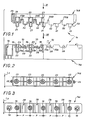
- the bars 10 which are metal bars made for example of copper, have a rectangular cross section.
- L1 be their width and L2 their thickness.
- insulating supports 14 are used along these bars 10 and / or at the end of them.
- the lower part 14A and the upper part 14B are in the form of bars which, in general parallelepiped configuration, extend perpendicular to the bars 10, presenting one and the other one the same width L3 and being superimposed on each other.
- the lower part 14A has a well 16 at each of its ends, for the passage of any fixing means, such as screw or other, suitable for its subjection to any medium.
- the housings 18 of the lower part 14A each extend by a well 22 beyond a shoulder 23 ensuring the support of the balusters 21 of the upper part 14B, and these columns 21, which themselves come in the extension of the well 25, are hollow.
- the upper part 14B also has, at each of its ends, in the embodiment more particularly shown in FIGS. 1 to 6, a well 26 suitable for the intervention of any fixing means, such as screws or the like.
- housings 15 are provided, including three for bars 10 of phase and one for a bar 10 of neutral.
- these housings 15 are established at regular intervals, at the same step P1 as the housings 18 and that the balusters 21 of the lower parts 14A and upper 14B.
- Each of them is surrounded by two of the fixing zones which constitute these housings 18 and these balusters 21.
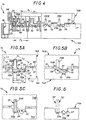
- these various positions each correspond respectively to various angular orientations of a bar 10 in a plane perpendicular thereto.
- This plane is the figure plane in FIGS. 4, 5A, 5B, 5C.
- At least one of the various housings 15, and in practice each of these, is formed directly by the lower part 14A and by the upper part 14B, in being formed at least in part, according to arrangements described in more detail later, by a notch or groove in the upper surface 17 of the lower part 14A and / or at least in part by a notch or groove in the lower surface 20 of the upper part 14B.
- the various housings 15 are all identical to each other, and each of them is capable of receiving a bar 10 according to any one of the following positions: flat, that is to say parallel to the interface between the lower part 14A and the upper part 14B, and, in practice, horizontally, at a zero angle, FIG. 5A; edge, that is to say perpendicular to the interface between the lower part 14A and the upper part 14B, and in practice vertically, at an angle of 90 °, FIG. 5C, or inclined, in an intermediate orientation between the two preceding ones, and for example at an angle of 30 ° relative to the interface between the lower part 14A and the upper part 14B, FIG. 5B.
- the lower part 14A has, transversely hollow on its upper surface 17, in this embodiment, a notch 28 which, of generally rectangular cross section, allows, if desired, to receive a flat bar 10 .
- This notch 28 therefore has a width which, substantially equal to the width L1 of the bars 10, is, in practice, slightly greater than the latter.
- the bottom 27 of this notch 28 itself has, transversely, recessed, at a distance from each other, at least two grooves 29A, 30A, one of rectangular cross section, for receiving edge of a bar 10, the other of triangular cross section, for inclined reception of such a bar 10.
- the groove 29A therefore has a width which, substantially equal to the thickness L2 of the bars 10, is in practice slightly greater than this.
- the groove 30A is formed by two flanks, which, both inclined, one at 60 ° the other at 30 °, jointly form a 90 ° dihedral.
- the upper part 14B In line with the groove 29A of rectangular cross section of the lower part 14A, the upper part 14B itself has, transversely, in hollow, on its lower surface 20, in the embodiment shown, a groove 29B of rectangular cross section having the same width L2 as the groove 29A.
- the upper part 14B has, on the projecting surface, on its lower surface 20, in the embodiment shown, a boss 32, of which at least part 33 of the lower surface extends parallel to the bottom 27 of the notch 28 of the lower part 14A .
- the arrangements are such that, as indicated above, the upper part 14B is fitted onto the lower part 14A, the boss 32 of the upper part 14B is partially engaged in the notch 28 of the lower part 14A and the part 33 of its lower surface is at a distance from the bottom 27 of this notch 28 substantially equal to the thickness L2 of the bars 10 while in practice being slightly greater than the latter.
- this part 35 of the lower surface of the boss 32 of the upper part 14B itself belongs to a groove 30B of triangular cross section which, transversely affecting the lower surface 20 of this upper part 14B, in correspondence with the groove 30A of triangular cross section of the lower part 14A, in the extension thereof, intersects, at its outlet, the groove 29B of rectangular cross section of the upper part 14B.
- the arrangements are such that, jointly, when, as indicated above, the upper part 14B is fitted onto the lower part 14A, on the one hand, the part 35 of the lower surface of the boss 32 of the upper part 14B is at a distance of the corresponding side of the groove 30A of triangular cross section of the part lower 14A substantially equal to the thickness L2 of the bars 10 while in practice being slightly greater than the latter, and, on the other hand, the opposite sides of the grooves 30A, 30B of triangular cross section of the lower part 14A and of the upper part 14B are at a distance from each other substantially equal to the width L1 of these bars 10 while in practice being slightly greater than the latter.
- a bar 10 can, as desired, depending on the needs of the moment, be placed either flat, FIG. 5A, or in an inclined position, FIG. 5B, or song, Figure 5C.
- the upper part 14B has in correspondence, in this case, two grooves of rectangular cross section of appropriate width.
- At least one of the housings 15, and in practice each of these, is formed between two semi-cylindrical shells 36A, 36B which are capable of enclosing a bar 10 between them according to a single position well determined for it, and which, like a barrel, are jointly mounted generally angularly adjustable in position between the lower part 14A and the upper part 14B, by rotation about the axis along which transversely extends such a housing 15.
- indexing means are provided between the two shells 36A, 36B and the lower part 14A and / or the upper part 14B.
- the bars 10 can thus be each individually arranged flat, in an inclined position or edge, as before, but they can also be arranged in various other intermediate positions between the previous ones.
- connection device 42 comprising, as shown in FIGS. 8 and 9, two brackets 43, 43 ', which, attached to one another by one of their wings 44, 44 ', are generally angularly adjustable in position relative to each other, by rotation around a screw-nut assembly 45 ensuring their assembly , and which, by the other of their wings 46, 46 ', are each capable of being fixed, one on a bar 10, the other on the apparatus 11 to be connected to the latter.
- connection device 42 As illustrated in FIGS. 8 to 13, it is possible, by virtue of such a connection device 42, by rotation relative to one another of its two brackets 43, 43 ′, to be satisfied very simply with the various possible positions of the bar 10 relative to the device 11.
- the bore 48 that the wing 44, 44 ′ has of the brackets 43, 43 ′ for the passage of the screw-nut assembly 45 may, for at least one of the brackets 43, 43 ', and this is the bracket 43' in Figure 14, be more or less elongated laterally buttonhole.
Landscapes
- Distribution Board (AREA)
Applications Claiming Priority (2)
| Application Number | Priority Date | Filing Date | Title |
|---|---|---|---|
| FR9211247A FR2696053B1 (fr) | 1992-09-22 | 1992-09-22 | Support isolant pour barres d'alimentation ou de distribution électrique. |
| FR9211247 | 1992-09-22 |
Publications (2)
| Publication Number | Publication Date |
|---|---|
| EP0589775A1 true EP0589775A1 (de) | 1994-03-30 |
| EP0589775B1 EP0589775B1 (de) | 1996-12-27 |
Family
ID=9433732
Family Applications (1)
| Application Number | Title | Priority Date | Filing Date |
|---|---|---|---|
| EP19930402300 Expired - Lifetime EP0589775B1 (de) | 1992-09-22 | 1993-09-21 | Isolierter Träger für elektrische Förder- oder Verteilungsschienen |
Country Status (3)
| Country | Link |
|---|---|
| EP (1) | EP0589775B1 (de) |
| DE (1) | DE69306894T2 (de) |
| FR (1) | FR2696053B1 (de) |
Cited By (4)
| Publication number | Priority date | Publication date | Assignee | Title |
|---|---|---|---|---|
| EP0681355A1 (de) * | 1994-05-06 | 1995-11-08 | Schneider Electric Sa | Sammelschienenanordnung, insbesondere für eine Energieverteilungsschrank |
| DE19511358A1 (de) * | 1995-03-28 | 1996-10-02 | Kloeckner Moeller Gmbh | Stromschienenträger für Niederspannungs-Energieverteiler |
| WO2008089826A1 (de) * | 2007-01-26 | 2008-07-31 | Rittal Gmbh & Co. Kg | Tragvorrichtung für stromsammelschienen |
| EP2408072A3 (de) * | 2010-07-15 | 2013-10-30 | Hager Electro GmbH & Co. KG | Verteilervorrichtung |
Families Citing this family (3)
| Publication number | Priority date | Publication date | Assignee | Title |
|---|---|---|---|---|
| DE102004022606A1 (de) | 2004-05-07 | 2005-12-15 | Envisiontec Gmbh | Verfahren zur Herstellung eines dreidimensionalen Objekts mit verbesserter Trennung ausgehärteter Materialschichten von einer Bauebene |
| DE102007029081A1 (de) * | 2007-06-21 | 2008-12-24 | Vamotec Ag | Sammelschienenhalter |
| US8372330B2 (en) | 2009-10-19 | 2013-02-12 | Global Filtration Systems | Resin solidification substrate and assembly |
Citations (6)
| Publication number | Priority date | Publication date | Assignee | Title |
|---|---|---|---|---|
| GB833041A (en) * | 1957-04-23 | 1960-04-21 | Simplex Electric Co Ltd | Improvements in or relating to electric busbars |
| CH389058A (fr) * | 1962-03-23 | 1965-03-15 | Merlin Gerin | Installation de distribution d'énergie électrique comprenant deux jeux de barres collectrices |
| CH486754A (de) * | 1966-05-17 | 1970-02-28 | Elin Union Ag | Bausatz zum Aufbau einer Isolierträgeranordnung für mindestens eine Stromschiene |
| US3538390A (en) * | 1967-11-13 | 1970-11-03 | Westinghouse Electric Corp | Circuit breaker and bus conductor combination |
| DE2436154A1 (de) * | 1974-07-26 | 1976-02-12 | Siemens Ag | Sammelschienenhalter |
| CH652535A5 (en) * | 1984-11-28 | 1985-11-15 | Sprecher & Schuh Ag | Connecting arrangement at the ends of two rigid electrical conductors |
-
1992
- 1992-09-22 FR FR9211247A patent/FR2696053B1/fr not_active Expired - Fee Related
-
1993
- 1993-09-21 EP EP19930402300 patent/EP0589775B1/de not_active Expired - Lifetime
- 1993-09-21 DE DE1993606894 patent/DE69306894T2/de not_active Expired - Fee Related
Patent Citations (6)
| Publication number | Priority date | Publication date | Assignee | Title |
|---|---|---|---|---|
| GB833041A (en) * | 1957-04-23 | 1960-04-21 | Simplex Electric Co Ltd | Improvements in or relating to electric busbars |
| CH389058A (fr) * | 1962-03-23 | 1965-03-15 | Merlin Gerin | Installation de distribution d'énergie électrique comprenant deux jeux de barres collectrices |
| CH486754A (de) * | 1966-05-17 | 1970-02-28 | Elin Union Ag | Bausatz zum Aufbau einer Isolierträgeranordnung für mindestens eine Stromschiene |
| US3538390A (en) * | 1967-11-13 | 1970-11-03 | Westinghouse Electric Corp | Circuit breaker and bus conductor combination |
| DE2436154A1 (de) * | 1974-07-26 | 1976-02-12 | Siemens Ag | Sammelschienenhalter |
| CH652535A5 (en) * | 1984-11-28 | 1985-11-15 | Sprecher & Schuh Ag | Connecting arrangement at the ends of two rigid electrical conductors |
Cited By (8)
| Publication number | Priority date | Publication date | Assignee | Title |
|---|---|---|---|---|
| EP0681355A1 (de) * | 1994-05-06 | 1995-11-08 | Schneider Electric Sa | Sammelschienenanordnung, insbesondere für eine Energieverteilungsschrank |
| FR2719718A1 (fr) * | 1994-05-06 | 1995-11-10 | Schneider Electric Sa | Dispositif de jeu de barres, notamment pour une armoire de distribution électrique. |
| US5847321A (en) * | 1994-05-06 | 1998-12-08 | Schneider Electric Sa | Busbar device for an electrical distribution cabinet |
| DE19511358A1 (de) * | 1995-03-28 | 1996-10-02 | Kloeckner Moeller Gmbh | Stromschienenträger für Niederspannungs-Energieverteiler |
| WO2008089826A1 (de) * | 2007-01-26 | 2008-07-31 | Rittal Gmbh & Co. Kg | Tragvorrichtung für stromsammelschienen |
| US8319106B2 (en) | 2007-01-26 | 2012-11-27 | Rittal Gmbh & Co. Kg | Carrying device for busbars |
| CN104638590B (zh) * | 2007-01-26 | 2017-05-17 | 利塔尔两合公司 | 用于电流汇流排的支承装置 |
| EP2408072A3 (de) * | 2010-07-15 | 2013-10-30 | Hager Electro GmbH & Co. KG | Verteilervorrichtung |
Also Published As
| Publication number | Publication date |
|---|---|
| EP0589775B1 (de) | 1996-12-27 |
| FR2696053A1 (fr) | 1994-03-25 |
| FR2696053B1 (fr) | 1994-11-25 |
| DE69306894T2 (de) | 1997-05-07 |
| DE69306894D1 (de) | 1997-02-06 |
Similar Documents
| Publication | Publication Date | Title |
|---|---|---|
| EP3323171B1 (de) | Isolator für eine schwenkbare elektrische verbindung | |
| FR2593647A1 (fr) | Bloc de jonction a rapporter sur un profile. | |
| EP0487365B1 (de) | Positionierungskeil zum Blockieren eines elektrischen Kabelschuhes | |
| EP0589775B1 (de) | Isolierter Träger für elektrische Förder- oder Verteilungsschienen | |
| FR2860650A1 (fr) | Connecteur electrique muni d'un systeme de deconnexion rapide | |
| FR2727260A1 (fr) | Support pour appareillage electrique | |
| EP0063087B1 (de) | Bürstenhalteranordnung für elektrische Motoren, insbesondere Zugmotoren | |
| FR2762449A1 (fr) | Connecteur electrique auquel il est associe une cale d'epaisseur, et cale d'epaisseur correspondante | |
| EP1065749B1 (de) | Verbindungszusatzgerät für elektrische Apparate, ins besondere für modulare elektrische Apparate | |
| FR2769418A1 (fr) | Serre-cable et appareil electrique equipe d'un tel serre-cable | |
| EP0961353B1 (de) | Anschlussvorrichtung für einen Kabelausgang oder eine Abzweigung | |
| EP1107363B1 (de) | Monopolarer Modularerverteiler | |
| EP0817318B1 (de) | Anschlussbuchse für kammförmige Sammelschiene, insbesondere für modulare elektrische Geräte | |
| EP0762585A1 (de) | Befestigungszubehör zur Montage an ein Gestell, insbesondere für Befestigung von elektrischen Apparaten | |
| FR2584243A1 (fr) | Plastron a fenetre pour goulotte | |
| FR2665326A1 (fr) | Support pour appareil electrique. | |
| FR2775542A1 (fr) | Support de barre(s) a logement(s) pouvant recevoir des barres de sections transversales differentes | |
| FR2744847A1 (fr) | Dispositif de fixation pour chassis a rapporter sur un support, chassis propre a la mise en oeuvre d'un tel dispositif de fixation, et coffret, en particulier coffret electrique, comportant un tel chassis | |
| FR2638033A1 (fr) | Support isolant multifonctionnel pour barreau de support pour appareillage electrique | |
| FR2749709A1 (fr) | Borne d'arrivee pour barre d'alimentation en forme de peigne notamment pour appareils electriques modulaires | |
| WO2021209626A1 (fr) | Dispositif d'interconnexion électrique pour mise à la terre de conducteurs électriques | |
| EP2439815A1 (de) | Elektrische Verbindungsvorrichtung, insbesondere für einen Kabelkanal bestimmt | |
| FR3087966A1 (fr) | Bloc de commande d'une machine electrique tournante et procede de montage d'un tel bloc de commande | |
| FR2771592A1 (fr) | Coffret equipe d'un rail de support pour de quelconques appareils, notamment pour de quelconques appareils electriques modulaires | |
| EP1111646A1 (de) | Elektrische Verbindungsanordnung zwischen einer Stromschiene und mindestens einem leitenden Kabel |
Legal Events
| Date | Code | Title | Description |
|---|---|---|---|
| PUAI | Public reference made under article 153(3) epc to a published international application that has entered the european phase |
Free format text: ORIGINAL CODE: 0009012 |
|
| AK | Designated contracting states |
Kind code of ref document: A1 Designated state(s): DE FR GB IT |
|
| 17P | Request for examination filed |
Effective date: 19940428 |
|
| 17Q | First examination report despatched |
Effective date: 19950704 |
|
| GRAG | Despatch of communication of intention to grant |
Free format text: ORIGINAL CODE: EPIDOS AGRA |
|
| GRAH | Despatch of communication of intention to grant a patent |
Free format text: ORIGINAL CODE: EPIDOS IGRA |
|
| GRAH | Despatch of communication of intention to grant a patent |
Free format text: ORIGINAL CODE: EPIDOS IGRA |
|
| GRAA | (expected) grant |
Free format text: ORIGINAL CODE: 0009210 |
|
| AK | Designated contracting states |
Kind code of ref document: B1 Designated state(s): DE FR GB IT |
|
| GBT | Gb: translation of ep patent filed (gb section 77(6)(a)/1977) |
Effective date: 19970102 |
|
| ITF | It: translation for a ep patent filed |
Owner name: FUMERO BREVETTI S.N.C. |
|
| REF | Corresponds to: |
Ref document number: 69306894 Country of ref document: DE Date of ref document: 19970206 |
|
| PLBE | No opposition filed within time limit |
Free format text: ORIGINAL CODE: 0009261 |
|
| STAA | Information on the status of an ep patent application or granted ep patent |
Free format text: STATUS: NO OPPOSITION FILED WITHIN TIME LIMIT |
|
| 26N | No opposition filed | ||
| REG | Reference to a national code |
Ref country code: GB Ref legal event code: IF02 |
|
| PGFP | Annual fee paid to national office [announced via postgrant information from national office to epo] |
Ref country code: GB Payment date: 20050826 Year of fee payment: 13 |
|
| PGFP | Annual fee paid to national office [announced via postgrant information from national office to epo] |
Ref country code: DE Payment date: 20050906 Year of fee payment: 13 |
|
| PGFP | Annual fee paid to national office [announced via postgrant information from national office to epo] |
Ref country code: IT Payment date: 20060930 Year of fee payment: 14 |
|
| PG25 | Lapsed in a contracting state [announced via postgrant information from national office to epo] |
Ref country code: DE Free format text: LAPSE BECAUSE OF NON-PAYMENT OF DUE FEES Effective date: 20070403 |
|
| GBPC | Gb: european patent ceased through non-payment of renewal fee |
Effective date: 20060921 |
|
| PG25 | Lapsed in a contracting state [announced via postgrant information from national office to epo] |
Ref country code: GB Free format text: LAPSE BECAUSE OF NON-PAYMENT OF DUE FEES Effective date: 20060921 |
|
| PGFP | Annual fee paid to national office [announced via postgrant information from national office to epo] |
Ref country code: FR Payment date: 20070926 Year of fee payment: 15 |
|
| REG | Reference to a national code |
Ref country code: FR Ref legal event code: ST Effective date: 20090529 |
|
| PG25 | Lapsed in a contracting state [announced via postgrant information from national office to epo] |
Ref country code: IT Free format text: LAPSE BECAUSE OF NON-PAYMENT OF DUE FEES Effective date: 20070921 |
|
| PG25 | Lapsed in a contracting state [announced via postgrant information from national office to epo] |
Ref country code: FR Free format text: LAPSE BECAUSE OF NON-PAYMENT OF DUE FEES Effective date: 20080930 |