EP0587887B1 - Vorrichtung und formverfahren für spritzgiessmaschine - Google Patents
Vorrichtung und formverfahren für spritzgiessmaschine Download PDFInfo
- Publication number
- EP0587887B1 EP0587887B1 EP91910150A EP91910150A EP0587887B1 EP 0587887 B1 EP0587887 B1 EP 0587887B1 EP 91910150 A EP91910150 A EP 91910150A EP 91910150 A EP91910150 A EP 91910150A EP 0587887 B1 EP0587887 B1 EP 0587887B1
- Authority
- EP
- European Patent Office
- Prior art keywords
- injection
- screw
- mold
- resin
- gate
- Prior art date
- Legal status (The legal status is an assumption and is not a legal conclusion. Google has not performed a legal analysis and makes no representation as to the accuracy of the status listed.)
- Expired - Lifetime
Links
Images

Classifications
-
- B—PERFORMING OPERATIONS; TRANSPORTING
- B29—WORKING OF PLASTICS; WORKING OF SUBSTANCES IN A PLASTIC STATE IN GENERAL
- B29C—SHAPING OR JOINING OF PLASTICS; SHAPING OF MATERIAL IN A PLASTIC STATE, NOT OTHERWISE PROVIDED FOR; AFTER-TREATMENT OF THE SHAPED PRODUCTS, e.g. REPAIRING
- B29C45/00—Injection moulding, i.e. forcing the required volume of moulding material through a nozzle into a closed mould; Apparatus therefor
- B29C45/17—Component parts, details or accessories; Auxiliary operations
- B29C45/76—Measuring, controlling or regulating
-
- B—PERFORMING OPERATIONS; TRANSPORTING
- B29—WORKING OF PLASTICS; WORKING OF SUBSTANCES IN A PLASTIC STATE IN GENERAL
- B29C—SHAPING OR JOINING OF PLASTICS; SHAPING OF MATERIAL IN A PLASTIC STATE, NOT OTHERWISE PROVIDED FOR; AFTER-TREATMENT OF THE SHAPED PRODUCTS, e.g. REPAIRING
- B29C45/00—Injection moulding, i.e. forcing the required volume of moulding material through a nozzle into a closed mould; Apparatus therefor
- B29C45/17—Component parts, details or accessories; Auxiliary operations
- B29C45/46—Means for plasticising or homogenising the moulding material or forcing it into the mould
- B29C45/56—Means for plasticising or homogenising the moulding material or forcing it into the mould using mould parts movable during or after injection, e.g. injection-compression moulding
- B29C45/561—Injection-compression moulding
Definitions
- the present invention relates to a device for and a method of molding for an injection molding machine, and more particulary to a device for and a method of molding for an injection molding machine by which fluctuation in weight of an injection-molded resin product is reduced.
- the following methods have been implemented to manufacture resin molded products by a molding device for an injection molding machine, an injection compression molding machine, and an extrusion molding machine.
- Document EP-A-0 365 684 discloses a molding device and method of an injection molding machine having a mold clamping unit, an injection unit, a gate opening/closing mechanism to give a precompression to molten resin.
- An object of the present invention made in view of the above problem is to provide a device and a method of molding for an injection molding machine capable of reducing fluctuation in weight of a resin molded product and providing stable quality.
- a molding device in accordance with the present invention for an injection molding machine is recited in claim 1.
- the screw is decelerated to the specified speed at a position 1 to 7 mm in front of the predetermined stop position. After deceleration is completed, the screw further moves forward at a speed of 10 mm/sec or less.
- the advancing speed of the screw is reduced and the molten resin feed rate is also reduced before the injection of a specified amount of molten resin into the mold is completed, and, therefore, the molten resin feed rate can be reduced before the gate closes, so that feed rate control is facilitated, and the molten resin feed rate can be accurately controlled because molten resin continues to be pressurized until the gate closes.
- FIG. 1 shows a general view of an injection molding machine according to an embodiment of the present invention
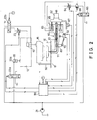
- FIG. 2 is an electrical circuit diagram including a hydraulic circuit diagram of the embodiment shown in FIG. 1
- FIG. 3 is an enlarged cross-sectional view of the resin passage varying mechanism.
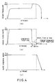
- FIGS. 4(a), 4 (b), and 4(c) are respectively graphs showing the relationship of the resin pressure, resin feed rate, and gate opening area to the stroke.
- FIG. 1 shows a general view of an embodiment of the present invention
- FIG. 2 is an electrical circuit diagram including a hydraulic circuit diagram of the embodiment
- FIG. 3 is an enlarged cross-sectional view of the resin passage varying mechanism.
- a molding device for an injection molding machine having a clamping unit 10 such as a press, which opens or closes the mold in a vertical direction and an injection unit 30 which is located below the die plate of the clamping unit 10 and feeds resin into the opened mold
- a base 45 which horizontally slides below the clamping unit 10
- a tractor unit not shown, which actuates the base 45 to slide horizontally
- a rocking block 48 which is supported by the base 45 at its one end and is rocked by an actuator 47 at its other end
- an injection unit 30 which is fixed to the rocking block 48
- a hydraulic unit 49 for an injection molding machine having a clamping unit 10 such as a press, which opens or closes the mold in a vertical direction and an injection unit 30 which is located below the die plate of the clamping
- the clamping unit 10 comprises four lift guide rods 11, a lift frame 12 which is supported by the lift guide rods 11 and moves in a vertical direction, an upper die plate 14 supported by four compression cylinders 13 incorporated in the lift frame 12, an upper mold 15 attached to the upper die plate 14, a lower mold 16 provided faced to the upper mold 15, a lower die plate 17 which holds the lower mold 16 and supports the lift guide rods 11, and a frame 18 which fixes the lower die plate 17, and vertically opens and closes the mold by the actuator 20.
- a mold position sensor 50 which detects the positions of the lower mold 16 and upper mold 15, is fixed to the lower die plate 17.
- the injection unit 30 comprises an injection mechanism 60, a gate opening/closing mechanism 70, a resin passage varying mechanism 80, and a controller 90.
- the actuator 20 and compression cylinders 13 are actuated by a hydraulic pressure supplied from the pump 21 through solenoid valves 22a and 22b.
- a flow control valve 23 is installed in the hydraulic circuit for the compression cylinders 13 to control the flow rate of hydraulic oil to the compression cylinders 13 in accordance with a command signal from the controller 90 which is responsive to a detection signal generated by the mold position sensor 50, to move up and down the upper mold 15 which is kept in parallel with the lower mold 16.
- This mold parallel drive mechanism comprises a mold position sensor 50, a flow control valve 23, a controller 90, and compression cylinders 13.
- the flow rate of oil in the hydraulic circuit for compression cylinders 13 can be controlled by a pump instead of the flow control valve 23.
- the injection mechanism 60 comprises a screw 61, a screw drive motor 62, an injection cylinder 63, a flow control valve 64, a solenoid valve 65, and a pressure regulating valve 66.
- the screw drive motor 62 rotates the screw 61 to knead and meter molten resin and the flow control valve 64 adjusts the oil flow rate to control sliding movement of the injection cylinder 63 to control the injection rate of molten resin.
- the quantity of resin to be injected is measured by detecting the position of the injection cylinder 63 with the injection cylinder position sensor 67.
- the gate opening/closing mechanism 70 and the resin passage varying mechanism 80 are installed on the injection nozzle 71 located between the lower mold 16 and the injection mechanism 60.
- the servo motor 91 is driven with a command signal from the controller 90 to open or close the valve 72 of the resin passage varying mechanism 80 through the gate opening/closing mechanism 70.
- the valve position sensor 92 detects the position of the valve 72.
- the gate opening area is determined by varying the relative position of the passage 81 provided inside the valve 72 and the injection nozzle 71.
- a molding method by means of a molding device for the injection molding machine of the present invention is described below, referring to FIG. 1 and the graphs 4(a) - 4(c).
- the lift frame 12 is lowered to the lowest point (i.e., the stroke of the actuator 20 is maximized) and the compression cylinders 13 are actuated to make the upper mold 15 and the lower mold 16 come in contact with each other while the stroke is maximized
- the heights of four lift guide rods 11 are individually adjusted by height adjusters 19 to ensure close contact of upper and lower molds 15 and 16.
- hydraulic pressure is transmitted to the port 20a of the actuator 20 to eliminate backlash, and adjustment is thus completed.
- the upper mold 15 is first lifted from the position at which it is in contact with the lower mold 16 and then lowered to a specified position (where the upper mold 15 and the lower mold 16 are slightly opened).
- the mold position sensor 50 detects that the upper mold 15 has reached the specified position, it transmits a detection signal to the controller 90 to stop the upper mold 15.
- the solenoid valve 65 is actuated with the command signal of the controller 90 to supply hydraulic oil from the pump 21 to the injection cylinder 63 to advance the screw 61 at the specified speed.
- the controller 90 which has received this detection signal, transmits a command signal to the flow control valve 64 to reduce the advancing speed of the screw 61. As shown in FIG.
- the deceleration of advancing of the screw 61 can be started at a position 1 to 7 mm in front of the predetermined stop position.
- a preferable advancing speed of the screw after deceleration can be 10 mm/sec or less.
- the stroke position sensor 67 detects the screw 61 and transmits a detection signal to the controller 90 to change over the solenoid valve 65 and stop the screw 61.
- the servo motor 91 is driven with this command signal from the controller 90 to start closing of the valve 72 of the gate opening/closing mechanism 70 as shown in FIG. 4(c).
- valve 72 is closed while the screw 61 is continuously moved forward and molten resin remains pressurized.
- the valve position sensor 92 detects the start of closing of the valve 72 and the controller 90, which has received this signal, transmits a command signal to the pressure regulating valve 66 to start the reduction of pressure to molten resin as shown in FIG. 4(a).
- the compression cylinders 13 are actuated to apply a pressure to the upper mold 15 to feed molten resin into the full range of the mold, thus reducing variations in the density of resin. Molding is completed.
- the table below shows the comparison data with respect to the quality of moldings according to the method of the present invention and the conventional method.
- the deviation ⁇ n-1 and inter-group fluctuation R of data obtained by the method according to the present invention are less than half those according to the conventional method, showing remarkable reduction of the variations.
Claims (4)
- Vorrichtung zum Formen (1) für eine Spritzgießmaschine, die ausgestattet ist mit einer Schließeinheit (10), die geschmolzenes Harz in ein geöffnetes Werkzeug einspeist und das Werkzeug zum Formen schließt, einer Einspritzeinheit (30), bestehend aus einer Schnecke (61), die das Schmelzen, Kneten und Einspritzen von Harz vornimmt, einem Verschlußöffnungs- und -schließmechanismus (70), der das Einspritzen von Harz beendet,einer Werkzeugpositionsaufnahmeeinrichtung zum Aufnehmen einer Position des geöffneten Werkzeugs;einer Hubpositionsaufnahmeeinrichtung (50) zum Aufnehmen einer Hubposition der Einspritzeinheit;einer Drucksteuereinrichtung zum Steuern eines Harzeinspritzdrucks;einem Harzdurchsatz-Verstellmechanismus (80) zum Verschließen eines Verschlusses nachdem eine bestimmte Menge an Harz über den Verschluß eingespeist wurde; undeiner Verschlußstellungsmeßeinrichtung (72) zum Aufnehmen einer Stellung des Verschlusses beim Öffnen,
zu der gehören:eine Geschwindigkeitssteuereinrichtung zum Steuern einer Vorwärtsbewegungsgeschwindigkeit der Einspritzeinheit undeine Steuereinheit (90) zur Abgabe von Befehlssignalen an die Geschwindigkeitssteuereinrichtung, den Harzdurchsatz-Verstellmechanismus und die Drucksteuereinrichtung als Antwort auf Signale von den entsprechenden Aufnahmeeinrichtungen. - Verfahren zum Formen für eine Spritzgießmaschine, die geschmolzenes Harz in ein geöffnetes Werkzeug einspeist, komprimiert und kühlt,Aufnehmen einer Position des Werkzeugs mit Hilfe einer Werkzeugpositionsaufnahmeeinrichtung, wenn die Werkzeughälfte in eine bestimmte Position bewegt wird,Starten des Einspritzens von geschmolzenem Harz durch Vorwärtsbewegen einer Schnecke einer Einspritzeinheit entsprechend einem Signal dieser,Registrieren mit Hilfe einer Hubpositionsaufnahmeeinrichtung, wann die Schnecke eine bestimmte Position erreicht,Verringern der Eintragsmenge an geschmolzenem Harz je Zeiteinheit, während ein Verschluß mit Hilfe der Verschlußöffnungs und -schließeinrichtung geschlossen wird, undBeaufschlagen des geschmolzenen Harzes mit Hilfe der Drucksteuerungseinrichtung, bis das Schließen des Verschlusses beendet ist,
das folgendes umfaßt:Verringern der Vorwärtsbewegungsgeschwindigkeit der Schnecke auf einen bestimmten Wert mit Hilfe einer Geschwindigkeitssteuereinrichtung entsprechend einem Signal von der Hubpositionsaufnahmeeinrichtung undStoppen der Schnecke mit Hilfe der Geschwindigkeitssteuerungseinrichtung, wenn die Schnecke mittels ähnlicher Einrichtungen eine bestimmte Stopposition erreicht. - Verfahren zum Formen für eine Spritzgießmaschine nach Anspruch 2, bei dem die Geschwindigkeit der Schnecke der Einspritzeinheit in einem Abstand von 1 bis 7 mm vor der festgelegten Stopposition auf einen bestimmten Wert verringert wird.
- Verfahren zum Formen für eine Spritzgießmaschine nach Anspruch 2, bei dem die Vorwärtsbewegungsgeschwindigkeit der Schnecke der Einspritzeinheit 10 mm/s oder weniger beträgt, nachdem die Schneckengeschwindigkeit herabgesetzt wurde.
Applications Claiming Priority (2)
| Application Number | Priority Date | Filing Date | Title |
|---|---|---|---|
| CA002103269A CA2103269C (en) | 1991-05-31 | 1991-05-31 | Device for and method of molding for injection molding machine |
| PCT/JP1991/000738 WO1992021504A1 (fr) | 1991-05-31 | 1991-05-31 | Appareil et procede de moulage pour machine a moulage par injection |
Publications (3)
| Publication Number | Publication Date |
|---|---|
| EP0587887A1 EP0587887A1 (de) | 1994-03-23 |
| EP0587887A4 EP0587887A4 (de) | 1994-04-27 |
| EP0587887B1 true EP0587887B1 (de) | 1997-12-03 |
Family
ID=25676514
Family Applications (1)
| Application Number | Title | Priority Date | Filing Date |
|---|---|---|---|
| EP91910150A Expired - Lifetime EP0587887B1 (de) | 1991-05-31 | 1991-05-31 | Vorrichtung und formverfahren für spritzgiessmaschine |
Country Status (4)
| Country | Link |
|---|---|
| US (1) | US5470513A (de) |
| EP (1) | EP0587887B1 (de) |
| CA (1) | CA2103269C (de) |
| WO (1) | WO1992021504A1 (de) |
Families Citing this family (5)
| Publication number | Priority date | Publication date | Assignee | Title |
|---|---|---|---|---|
| JP2787651B2 (ja) * | 1994-03-22 | 1998-08-20 | 日精樹脂工業株式会社 | 射出成形機の成形方法 |
| JP2838647B2 (ja) * | 1994-05-16 | 1998-12-16 | 住友重機械工業株式会社 | 射出成形機におけるエジェクタ機構のエジェクタ戻限完了位置設定方法及び装置 |
| US6500376B1 (en) | 2000-01-27 | 2002-12-31 | Visteon Global Technologies, Inc. | Multiple injection compression molding process |
| JP2006034285A (ja) * | 2004-06-22 | 2006-02-09 | Satako:Kk | 食品生地の発酵成形方法、発酵成形装置及び成形体 |
| ITMO20050208A1 (it) * | 2005-08-05 | 2007-02-06 | Sacmi | Dispositivo erogatore |
Family Cites Families (12)
| Publication number | Priority date | Publication date | Assignee | Title |
|---|---|---|---|---|
| JPS58179625A (ja) * | 1982-04-15 | 1983-10-20 | Nippon Denso Co Ltd | 射出成形加工におけるボイド消去方法及び装置 |
| FR2545033B1 (fr) * | 1983-04-28 | 1985-08-16 | Cibie Projecteurs | Procede et dispositif pour la realisation de pieces en matiere plastique, sur presse a injection |
| JPS6216119A (ja) * | 1985-07-15 | 1987-01-24 | Hitachi Ltd | 射出圧縮成形金型のゲ−ト閉鎖装置 |
| US4846651A (en) * | 1986-03-27 | 1989-07-11 | Kabushiki Kaisha Komatsu Seisakusho | Injection molding machine |
| JPH01234222A (ja) * | 1988-03-15 | 1989-09-19 | Komatsu Ltd | 射出圧縮成形機の成形方法およびその成形装置 |
| JPH0637070B2 (ja) * | 1988-03-24 | 1994-05-18 | 株式会社小松製作所 | 射出圧縮成形機の成形装置および成形方法 |
| AU620138B2 (en) * | 1988-08-31 | 1992-02-13 | Kabushiki Kaisha Komatsu Seisakusho | Injection press composite molding machine |
| JPH02153717A (ja) * | 1988-10-27 | 1990-06-13 | Komatsu Ltd | 射出圧縮成形装置およびその成形方法 |
| JPH0777734B2 (ja) * | 1988-10-31 | 1995-08-23 | 株式会社小松製作所 | 熱可塑性樹脂のプレス成形装置およびその制御方法 |
| WO1990004508A1 (fr) * | 1988-10-27 | 1990-05-03 | Kabushiki Kaisha Komatsu Seisakusho | Machine de moulage par injection-compression et procede de moulage |
| JP2787581B2 (ja) * | 1988-10-31 | 1998-08-20 | 株式会社小松製作所 | プラスチック圧縮成形機の温度調節装置 |
| JP2628357B2 (ja) * | 1988-10-31 | 1997-07-09 | 株式会社小松製作所 | インジェクションプレスの型締装置およびその制御方法 |
-
1991
- 1991-05-31 CA CA002103269A patent/CA2103269C/en not_active Expired - Fee Related
- 1991-05-31 EP EP91910150A patent/EP0587887B1/de not_active Expired - Lifetime
- 1991-05-31 US US08/142,458 patent/US5470513A/en not_active Expired - Fee Related
- 1991-05-31 WO PCT/JP1991/000738 patent/WO1992021504A1/ja active IP Right Grant
Also Published As
| Publication number | Publication date |
|---|---|
| EP0587887A4 (de) | 1994-04-27 |
| CA2103269C (en) | 1998-06-16 |
| EP0587887A1 (de) | 1994-03-23 |
| CA2103269A1 (en) | 1992-12-01 |
| WO1992021504A1 (fr) | 1992-12-10 |
| US5470513A (en) | 1995-11-28 |
Similar Documents
| Publication | Publication Date | Title |
|---|---|---|
| EP0397883B1 (de) | Einspritzverdichtungsgiessvorrichtung und deren verfahren | |
| US4917840A (en) | Mold compression control process for an injection molding machine and apparatus thereof | |
| CA1116365A (en) | Sensing system and method for plastic injection molding | |
| US5389315A (en) | Method and device for mold press forming | |
| AU621162B2 (en) | Injection press machine and its molding method | |
| US4889478A (en) | Apparatus for operating an injection compression molding machine | |
| EP0587887B1 (de) | Vorrichtung und formverfahren für spritzgiessmaschine | |
| JPH0523575B2 (de) | ||
| DE102009039582A1 (de) | Einspritzsteuervorrichtung und Einspritzsteuerverfahren | |
| EP0369009B1 (de) | Vorrichtung und verfahren zum giessformen durch einspritz-verdichtung | |
| US4222725A (en) | Electro-hydraulic ram control apparatus | |
| KR0170750B1 (ko) | 사출성형기의 충전량 검출방법 | |
| JPH03236917A (ja) | 熱可塑性樹脂のプレス成形装置およびその成形方法と、その成形金型 | |
| JPH07121546B2 (ja) | 射出圧縮機の成形方法 | |
| JPS6332607B2 (de) | ||
| JPS63157800A (ja) | プレス機におけるスライドの動的平衡精度維持装置 | |
| JPH02153710A (ja) | 熱可塑性樹脂のプレス成形装置およびその制御方法 | |
| JPH0465766B2 (de) | ||
| JPH0994856A (ja) | 射出成形用金型 | |
| JP2926355B2 (ja) | 射出プレス成形方法 | |
| JPS62227616A (ja) | 射出成形における金型内樹脂圧力の検出方法 | |
| JPH08323832A (ja) | 射出圧縮成形方法および装置 | |
| JPH04246523A (ja) | 射出圧縮成形方法 | |
| JP2005014471A (ja) | 射出プレス成形方法 | |
| JPH03278928A (ja) | プラスチック成形機のロケートリング |
Legal Events
| Date | Code | Title | Description |
|---|---|---|---|
| PUAI | Public reference made under article 153(3) epc to a published international application that has entered the european phase |
Free format text: ORIGINAL CODE: 0009012 |
|
| 17P | Request for examination filed |
Effective date: 19931124 |
|
| AK | Designated contracting states |
Kind code of ref document: A1 Designated state(s): DE |
|
| A4 | Supplementary search report drawn up and despatched |
Effective date: 19940309 |
|
| AK | Designated contracting states |
Kind code of ref document: A4 Designated state(s): DE |
|
| 17Q | First examination report despatched |
Effective date: 19950728 |
|
| GRAG | Despatch of communication of intention to grant |
Free format text: ORIGINAL CODE: EPIDOS AGRA |
|
| GRAG | Despatch of communication of intention to grant |
Free format text: ORIGINAL CODE: EPIDOS AGRA |
|
| GRAH | Despatch of communication of intention to grant a patent |
Free format text: ORIGINAL CODE: EPIDOS IGRA |
|
| GRAH | Despatch of communication of intention to grant a patent |
Free format text: ORIGINAL CODE: EPIDOS IGRA |
|
| GRAA | (expected) grant |
Free format text: ORIGINAL CODE: 0009210 |
|
| AK | Designated contracting states |
Kind code of ref document: B1 Designated state(s): DE |
|
| REF | Corresponds to: |
Ref document number: 69128360 Country of ref document: DE Date of ref document: 19980115 |
|
| PLBE | No opposition filed within time limit |
Free format text: ORIGINAL CODE: 0009261 |
|
| STAA | Information on the status of an ep patent application or granted ep patent |
Free format text: STATUS: NO OPPOSITION FILED WITHIN TIME LIMIT |
|
| 26N | No opposition filed | ||
| PGFP | Annual fee paid to national office [announced via postgrant information from national office to epo] |
Ref country code: DE Payment date: 20000529 Year of fee payment: 10 |
|
| PG25 | Lapsed in a contracting state [announced via postgrant information from national office to epo] |
Ref country code: DE Free format text: LAPSE BECAUSE OF NON-PAYMENT OF DUE FEES Effective date: 20020301 |