EP0584635B1 - Dispositif pour l'obtention de la configuration d'ouverture d'un réseau d'antennes à commande de phase - Google Patents
Dispositif pour l'obtention de la configuration d'ouverture d'un réseau d'antennes à commande de phase Download PDFInfo
- Publication number
- EP0584635B1 EP0584635B1 EP93112787A EP93112787A EP0584635B1 EP 0584635 B1 EP0584635 B1 EP 0584635B1 EP 93112787 A EP93112787 A EP 93112787A EP 93112787 A EP93112787 A EP 93112787A EP 0584635 B1 EP0584635 B1 EP 0584635B1
- Authority
- EP
- European Patent Office
- Prior art keywords
- signal
- monitor
- additional
- integral
- waveguide
- Prior art date
- Legal status (The legal status is an assumption and is not a legal conclusion. Google has not performed a legal analysis and makes no representation as to the accuracy of the status listed.)
- Expired - Lifetime
Links
Images

Classifications
-
- H—ELECTRICITY
- H01—ELECTRIC ELEMENTS
- H01Q—ANTENNAS, i.e. RADIO AERIALS
- H01Q3/00—Arrangements for changing or varying the orientation or the shape of the directional pattern of the waves radiated from an antenna or antenna system
- H01Q3/26—Arrangements for changing or varying the orientation or the shape of the directional pattern of the waves radiated from an antenna or antenna system varying the relative phase or relative amplitude of energisation between two or more active radiating elements; varying the distribution of energy across a radiating aperture
- H01Q3/267—Phased-array testing or checking devices
Definitions
- the invention relates to a device according to the preamble of patent claim 1.
- Such a device is known both from DE-OS 40 12 101 A1 and from US Pat. No. 4,926,186. It will e.g. used to monitor phase-controlled group antennas in microwave landing systems (MLS systems).
- MLS systems microwave landing systems
- the course of the antenna far field is monitored. Since the antenna far field is linked to the aperture assignment of the antenna via a Fourier transformation, monitoring the far field not only allows deviations in the phase assignment but also deviations in the Detect the amplitude assignment of the individual antenna elements.
- the course of the far field of a phase-controlled group antenna can be recorded in addition to direct field measurements using a so-called integral monitor waveguide, a waveguide component that is arranged parallel to the group axis of the antenna in the vicinity of the antenna elements (radiators) and is coupled to the radiation fields of the individual antenna elements via coupling openings.
- the field components originating from the individual antenna elements overlap to form a monitor signal, which can be taken from an output of the integral monitor waveguide and whose course, with a sufficiently large swivel range of the antenna lobe, except for an angular offset with respect to the perpendicular to the antenna group axis, the so-called monitor angle or observation angle, corresponds to the far field diagram in a good approximation.
- the observation angle by which the monitor signal is offset from the vertical of the antenna group axis can be influenced within certain limits by the dimensions of the integral monitor waveguide and by the design of the coupling openings. It can be taken into account when calculating the aperture assignment of the antenna, so that this calculation can be carried out from this monitor signal by means of a Fourier transformation, despite the monitor signal being offset by the observation angle.
- a prerequisite for a good match of the monitor signal obtained from the integral monitor waveguide with the far field diagram of the antenna and thus a prerequisite for a correct calculation of the aperture assignment of the antenna is that the antenna is pivoted over a sufficiently large angular range.
- This angular range should cover at least one full period of the far field diagram, so that the Fourier transform field information from an entire period of the far field diagram is available.
- the swivel range required for the calculation of the aperture assignment is expanded in the best case to double. If the two outputs are provided, for example, at both ends of the integral monitor waveguide, as claimed in claim 2, the first output delivers a monitor signal which only contains information from a partial area of the entire far field diagram corresponding to the width of the swivel area. The location of this information-providing, ie "visible" area within the far field diagram is determined by the observation angle ⁇ .
- the second output at the other end of the integral monitor waveguide supplies a monitor signal which likewise only contains information from a partial area of the far field diagram corresponding to the width of the swivel area. However, this sub-area is visible at a different observation angle, namely the mirror-angle 0 to the central perpendicular to the antenna group axis. If the swivel range is not too limited, it is now possible to use the monitor signals obtained at both outputs or their processed signal parts in addition to each other. If the position and width of the visible subareas can be adjusted in such a way that they cover a period of the far field diagram, then an exact calculation of the aperture assignment of the antenna can be carried out. In extreme cases, e.g.
- the swivel range is so limited (e.g. only 15 °) that even by additional evaluation of the monitor signal obtained from a second output of the integral monitor waveguide, no visible area corresponding to a full period of the far field diagram can be put together.
- one or more further signal monitor waveguides can be used, the monitor angles of which are set such that the assigned visible areas of the far field diagram cover the angular ranges of a period not covered by the visible areas of the first integral monitor waveguide.
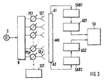
- a transmitter S feeds a number of antenna elements (radiators) SE1 ... SEn via a network N.
- the high-frequency energy is supplied to the antenna elements via phase shifters PS1 ... PSn upstream of the individual antenna elements, usually PIN diodes, which are controlled by a beam control unit SST at individually predetermined times and each set a predetermined phase shift.
- An integral monitor waveguide MH is arranged in the vicinity of the radiator, parallel to the group axis of the antenna, which has a coupling opening (not shown in the figure) at the level of the individual radiators and whose output A is connected to a signal processing circuit SV via a signal conditioning circuit SAB and a downstream analog / digital converter AD.
- the signal processing circuit contains a fast signal processor which is capable of performing mathematical operations such as Fast Fourier transforms in real time.
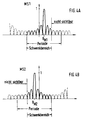
- the known device shown in FIG. 1 evaluates a monitor signal, which is shown in FIG. 2.
- This signal is generated in the integral monitor waveguide MH by superimposing the portions of the MLS transmission signal which come from the individual antenna elements and which are coupled into the waveguide via the coupling openings and which have different phase shifts.
- the monitor signal taken from output A corresponds to the far field diagram of the MLS antenna except for an angular offset with respect to the vertical on the antenna group axis, the observation angle ⁇ M.
- the aperture assignment of the antenna can thus be calculated from this monitor signal by means of a Fourier transformation, and predetermined test values can be compared with stored setpoints to monitor the proper functioning of the transmitter.
- Various methods for signal processing and calculation of the aperture assignment are described in the aforementioned DE-OS 40 12 101.
- the integral monitor waveguide MH in contrast to the arrangement shown in FIG. 1, has two opposite outputs A1 and A2.
- a signal processing circuit SAB1, SAB2 is connected downstream of each input conditioned monitor signal via an analog / digital converter AD1, AD2 a signal processing circuit SV supplies.
- the monitor signals MS1, MS2 to be taken at the outputs A1 and A2 differ from one another in their observation angle ⁇ M.
- ⁇ M observation angle
- different areas MS1, MS2 of the overall monitor signal corresponding to the far field diagram are visible under the different observation angles.
- the width of these visible areas corresponds to the swivel range of the antenna. Their position can be seen from FIGS. 4a and 4b:
- the monitor signal MS1 taken from the output A1 appears at an observation angle ⁇ M1 , seen from the center of the antenna (perpendicular to the axis of the antenna group), thus offset to the right.
- ⁇ M1 seen from the center of the antenna (perpendicular to the axis of the antenna group), thus offset to the right.
- Parts on the right-hand side of the total monitor signal that is one period wide and necessary for calculating the aperture assignment remain invisible.
- the left signal side is visible until the start of the period.
- the observation angle ⁇ M2 with respect to the center of the antenna is a mirror image of that of the monitor signal MS1, ie offset to the left from the center of the antenna.
- the visible area covered by the monitor signal thus comprises portions of the total monitor signal which extend to the right limit of the signal period, while signal portions remain invisible on the left edge of the signal period. It can be seen from FIGS. 4a and 4b that the monitor signals MS1 and MS2 taken together contain the entire information of one period of the monitor signal. The sampling values required for calculating the aperture assignment can thus be obtained from the two monitor signals when the different observation angles are taken into account numerically.
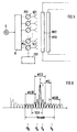
- a second integral monitor waveguide MH2 is provided in an exemplary embodiment shown in FIG. 5, the outputs of which are located at both ends of the monitor signals are also taken.
- FIG. 6 shows how, in the case of an antenna with a severely restricted swiveling range, an entire period of an overall monitor signal comprising four monitor signals MSI ... MSIV with a limited width with the observation angles ⁇ A , - ⁇ A , ⁇ B , - ⁇ B can be put together.
Landscapes
- Variable-Direction Aerials And Aerial Arrays (AREA)
Claims (3)
- Dispositif d'obtention de l'occupation du champ d'ouverture d'un réseau d'antennes à commande de phase, qui présente plusieurs antennes élémentaires (SE1...SEn) couplées par l'intermédiaire d'ouvertures de couplage à un guide d'ondes à moniteur intégral (MH), avec un circuit de préparation de signaux (SAB) qui est raccordé à une première sortie (A) du guide d'ondes à moniteur intégral et qui détermine et amène la partie réelle et la partie imaginaire, mais au moins la partie réelle, d'un signal moniteur complexe fonction du temps, prélevable au niveau de guide d'ondes à moniteur intégral, à un circuit de traitement de signaux (SV) qui calcule en permanence l'occupation du champ d'ouverture du réseau d'antennes à l'aide d'un processeur de signaux à partir des parties du signal moniteur déterminées par le circuit de préparation des signaux, caractérisé en ce que le guide d'ondes à moniteur intégral (MH1, MH2) présente au moins une autre sortie (A2) à distance de la première sortie (A1), qui est raccordée à un autre circuit de préparation de signaux (SAB2) qui détermine la partie réelle et la partie imaginaire, ou seulement la partie réelle, d'un signal moniteur complexe fonction du temps, prélevable à l'autre sortie et les amène au circuit de traitement de signaux (SV), et en ce que le processeur de signaux du circuit de préparation de signaux utilise pour le calcul de l'occupation du champ d'ouverture du réseau d'antennes les parties du signal moniteur déterminées par l'autre circuit de préparation de signaux (SAB2).
- Dispositif selon la revendication 1, caractérisé en ce que deux sorties (A1, A2) du guide d'ondes à moniteur intégral (MH) sont prévues aux extrémités opposées de cet élément.
- Dispositif selon les revendications 1 ou 2, caractérisé en ce que sont prévus un ou plusieurs guides d'ondes à moniteur intégral (MH2), aux sorties desquels sont à prélever des signaux moniteurs sous des angles d'observation autres que ceux sous lesquels les signaux moniteurs sont prélevés aux sorties du premier guide d'ondes à moniteur intégral, en ce qu'aux sorties de cet ou de ces autres guides d'ondes à moniteur intégral sont raccordés d'autres circuits de préparation de signaux qui déterminent et amènent au processeur de signaux la partie réelle et la partie imaginaire, ou seulement la partie réelle, des signaux moniteurs (MSI...MSIV) prélevés au niveau des autres guides d'ondes à moniteur intégral, et en ce que le processeur de signaux utilise pour le calcul de l'occupation du champ d'ouverture les parties des signaux moniteurs déterminées par les autres circuits de préparation des signaux.
Applications Claiming Priority (2)
| Application Number | Priority Date | Filing Date | Title |
|---|---|---|---|
| DE4227857A DE4227857A1 (de) | 1992-08-22 | 1992-08-22 | Einrichtung zur Gewinnung der Aperturbelegung einer phasengesteuerten Gruppenantenne |
| DE4227857 | 1992-08-22 |
Publications (2)
| Publication Number | Publication Date |
|---|---|
| EP0584635A1 EP0584635A1 (fr) | 1994-03-02 |
| EP0584635B1 true EP0584635B1 (fr) | 1997-01-29 |
Family
ID=6466145
Family Applications (1)
| Application Number | Title | Priority Date | Filing Date |
|---|---|---|---|
| EP93112787A Expired - Lifetime EP0584635B1 (fr) | 1992-08-22 | 1993-08-10 | Dispositif pour l'obtention de la configuration d'ouverture d'un réseau d'antennes à commande de phase |
Country Status (6)
| Country | Link |
|---|---|
| US (1) | US5337059A (fr) |
| EP (1) | EP0584635B1 (fr) |
| JP (1) | JP3383369B2 (fr) |
| AU (1) | AU668192B2 (fr) |
| CA (1) | CA2104261C (fr) |
| DE (2) | DE4227857A1 (fr) |
Cited By (1)
| Publication number | Priority date | Publication date | Assignee | Title |
|---|---|---|---|---|
| CN102792521A (zh) * | 2010-03-18 | 2012-11-21 | 阿尔卡特朗讯 | 用于移动电信的有源天线阵列的校准 |
Families Citing this family (6)
| Publication number | Priority date | Publication date | Assignee | Title |
|---|---|---|---|---|
| DE19711655A1 (de) * | 1997-03-20 | 1998-09-24 | Alsthom Cge Alcatel | Integralmonitornetzwerk, Antennenanlage und Sendeanlage für ein Instrumentenlandesystem (ILS) |
| US5841394A (en) * | 1997-06-11 | 1998-11-24 | Itt Manufacturing Enterprises, Inc. | Self calibrating radar system |
| DE19953271A1 (de) * | 1999-11-06 | 2001-05-10 | Airsys Navigation Systems Gmbh | Sendeantenne |
| KR101012161B1 (ko) * | 2010-08-25 | 2011-02-07 | 엘아이지넥스원 주식회사 | 디지털 레이더의 안테나 패턴을 측정하기 위한 시스템 및 방법 |
| US8686896B2 (en) * | 2011-02-11 | 2014-04-01 | Src, Inc. | Bench-top measurement method, apparatus and system for phased array radar apparatus calibration |
| CN113866522B (zh) * | 2021-12-07 | 2022-02-22 | 成都锐芯盛通电子科技有限公司 | 一种相控阵天线的方向图测试方法及系统 |
Family Cites Families (6)
| Publication number | Priority date | Publication date | Assignee | Title |
|---|---|---|---|---|
| US4453164A (en) * | 1982-07-26 | 1984-06-05 | Rca Corporation | Method of determining excitation of individual elements of a phase array antenna from near-field data |
| US4536766A (en) * | 1982-09-07 | 1985-08-20 | Hazeltine Corporation | Scanning antenna with automatic beam stabilization |
| AU565039B2 (en) * | 1983-05-23 | 1987-09-03 | Hazeltine Corp. | Resonant waveguide aperture manifold |
| US4926186A (en) * | 1989-03-20 | 1990-05-15 | Allied-Signal Inc. | FFT-based aperture monitor for scanning phased arrays |
| NO177475C (no) * | 1990-04-14 | 1995-09-20 | Sel Alcatel Ag | Fremgangsmåte og apparat ved antenne |
| DE4012101A1 (de) * | 1990-04-14 | 1991-10-17 | Standard Elektrik Lorenz Ag | Verfahren und vorrichtung zur gewinnung der aperturbelegung von phasengesteuerten gruppenantennen |
-
1992
- 1992-08-22 DE DE4227857A patent/DE4227857A1/de not_active Withdrawn
-
1993
- 1993-08-10 EP EP93112787A patent/EP0584635B1/fr not_active Expired - Lifetime
- 1993-08-10 DE DE59305316T patent/DE59305316D1/de not_active Expired - Lifetime
- 1993-08-13 AU AU44634/93A patent/AU668192B2/en not_active Ceased
- 1993-08-17 CA CA002104261A patent/CA2104261C/fr not_active Expired - Fee Related
- 1993-08-23 JP JP20803093A patent/JP3383369B2/ja not_active Expired - Fee Related
- 1993-08-23 US US08/110,364 patent/US5337059A/en not_active Expired - Lifetime
Cited By (2)
| Publication number | Priority date | Publication date | Assignee | Title |
|---|---|---|---|---|
| CN102792521A (zh) * | 2010-03-18 | 2012-11-21 | 阿尔卡特朗讯 | 用于移动电信的有源天线阵列的校准 |
| CN102792521B (zh) * | 2010-03-18 | 2015-07-15 | 阿尔卡特朗讯 | 用于移动电信的有源天线阵列的校准 |
Also Published As
| Publication number | Publication date |
|---|---|
| JP3383369B2 (ja) | 2003-03-04 |
| EP0584635A1 (fr) | 1994-03-02 |
| JPH06196923A (ja) | 1994-07-15 |
| CA2104261A1 (fr) | 1994-02-23 |
| AU4463493A (en) | 1994-02-24 |
| DE4227857A1 (de) | 1994-02-24 |
| DE59305316D1 (de) | 1997-03-13 |
| AU668192B2 (en) | 1996-04-26 |
| CA2104261C (fr) | 2001-12-18 |
| US5337059A (en) | 1994-08-09 |
Similar Documents
| Publication | Publication Date | Title |
|---|---|---|
| DE69103879T2 (de) | Kollisionsvermeidungssendesystem mit automatischer eichung. | |
| DE3743123C2 (de) | Antennenvorrichtung | |
| DE69618814T2 (de) | Hybride-peilsystem mit amplituden/phasenvergleich | |
| DE2248325C2 (de) | Antenne zum Senden oder Empfangen mit schwenkbarem Strahlenbündel | |
| DE69317195T2 (de) | Verfahren zur Antenneeichung im Nahfeld für aktive Antenne | |
| DE69701165T2 (de) | Selbst-Eichung einer Gruppenantenne mit ungleichmässiger gegenseitiger Kupplung der Antennenelemente und willkürlicher Orientierung des Antennnengitters | |
| EP1530816B9 (fr) | Dispositif de calibrage pour un reseau d'antennes commutable et procede pour faire fonctionner ce dispositif | |
| EP2965382B1 (fr) | Système d'antennes à caractéristique directionnelle variable | |
| DE102010040749A1 (de) | Radarvorrichtung zum Abstrahlen und Empfangen elektrischer Wellen mit Gitterkeulen | |
| DE3042456A1 (de) | Antenne mit einer einrichtung zur drehung der polarisationsebene | |
| EP0584635B1 (fr) | Dispositif pour l'obtention de la configuration d'ouverture d'un réseau d'antennes à commande de phase | |
| DE69827493T2 (de) | Selbstkalibrierendes radarsystem | |
| DE69028680T2 (de) | Konstante Strahlbreiten aufweisende Abtastgruppenantenne | |
| DE3787832T2 (de) | Echtzeitanzeige der Strahlrichtung bei einer Anordnung zur Antennenstrahlsteuerung. | |
| DE2731485C1 (de) | Verfahren und Vorrichtung zur Stoerverminderung bei einem elektromagnetischen Rueckstrahl-Ortungsgeraet | |
| DE3787797T2 (de) | Halbleiter phasengesteuerte gruppenantenne mit kleinen nebenkeulen. | |
| EP0935825B1 (fr) | Capteur-radar pour vehicule | |
| DE2505697C1 (de) | Stroerschutzverfahren fuer eine Antenne mit elektronischer Strahlschwenkung und Antenne zur Anwendung des Verfahrens | |
| DE19627218A1 (de) | Radarvorrichtung | |
| DE2159140C3 (de) | Photoelektrisches Detektorsystem | |
| DE19927395A1 (de) | Vorrichtung und Verfahren zur Erhöhung der Winkelauflösung einer Antennenanordnung | |
| EP0023606B1 (fr) | Système d'antennes pour le repérage d'une source de signaux de micro-ondes | |
| DE3827589C2 (fr) | ||
| EP0249753B1 (fr) | Système d'aide à l'atterrissage à faisceau de balayage utilisant des micro-ondes | |
| DE3440666C2 (de) | Antistörverfahren und -vorrichtung für Radaranlagen sowie mit einer solchen Vorrichtung ausgestattete Radaranlage |
Legal Events
| Date | Code | Title | Description |
|---|---|---|---|
| PUAI | Public reference made under article 153(3) epc to a published international application that has entered the european phase |
Free format text: ORIGINAL CODE: 0009012 |
|
| AK | Designated contracting states |
Kind code of ref document: A1 Designated state(s): DE FR GB IT |
|
| 17P | Request for examination filed |
Effective date: 19940414 |
|
| GRAG | Despatch of communication of intention to grant |
Free format text: ORIGINAL CODE: EPIDOS AGRA |
|
| 17Q | First examination report despatched |
Effective date: 19960313 |
|
| GRAH | Despatch of communication of intention to grant a patent |
Free format text: ORIGINAL CODE: EPIDOS IGRA |
|
| GRAH | Despatch of communication of intention to grant a patent |
Free format text: ORIGINAL CODE: EPIDOS IGRA |
|
| GRAA | (expected) grant |
Free format text: ORIGINAL CODE: 0009210 |
|
| AK | Designated contracting states |
Kind code of ref document: B1 Designated state(s): DE FR GB IT |
|
| REF | Corresponds to: |
Ref document number: 59305316 Country of ref document: DE Date of ref document: 19970313 |
|
| GBT | Gb: translation of ep patent filed (gb section 77(6)(a)/1977) |
Effective date: 19970321 |
|
| ITF | It: translation for a ep patent filed | ||
| ET | Fr: translation filed | ||
| PLBE | No opposition filed within time limit |
Free format text: ORIGINAL CODE: 0009261 |
|
| 26N | No opposition filed | ||
| REG | Reference to a national code |
Ref country code: GB Ref legal event code: IF02 |
|
| PGFP | Annual fee paid to national office [announced via postgrant information from national office to epo] |
Ref country code: IT Payment date: 20100817 Year of fee payment: 18 Ref country code: FR Payment date: 20100824 Year of fee payment: 18 Ref country code: DE Payment date: 20100812 Year of fee payment: 18 |
|
| PGFP | Annual fee paid to national office [announced via postgrant information from national office to epo] |
Ref country code: GB Payment date: 20100811 Year of fee payment: 18 |
|
| GBPC | Gb: european patent ceased through non-payment of renewal fee |
Effective date: 20110810 |
|
| REG | Reference to a national code |
Ref country code: FR Ref legal event code: ST Effective date: 20120430 |
|
| PG25 | Lapsed in a contracting state [announced via postgrant information from national office to epo] |
Ref country code: IT Free format text: LAPSE BECAUSE OF NON-PAYMENT OF DUE FEES Effective date: 20110810 |
|
| REG | Reference to a national code |
Ref country code: DE Ref legal event code: R119 Ref document number: 59305316 Country of ref document: DE Effective date: 20120301 |
|
| PG25 | Lapsed in a contracting state [announced via postgrant information from national office to epo] |
Ref country code: GB Free format text: LAPSE BECAUSE OF NON-PAYMENT OF DUE FEES Effective date: 20110810 Ref country code: FR Free format text: LAPSE BECAUSE OF NON-PAYMENT OF DUE FEES Effective date: 20110831 |
|
| PG25 | Lapsed in a contracting state [announced via postgrant information from national office to epo] |
Ref country code: DE Free format text: LAPSE BECAUSE OF NON-PAYMENT OF DUE FEES Effective date: 20120301 |