EP1530816B9 - Dispositif de calibrage pour un reseau d'antennes commutable et procede pour faire fonctionner ce dispositif - Google Patents
Dispositif de calibrage pour un reseau d'antennes commutable et procede pour faire fonctionner ce dispositif Download PDFInfo
- Publication number
- EP1530816B9 EP1530816B9 EP03740191A EP03740191A EP1530816B9 EP 1530816 B9 EP1530816 B9 EP 1530816B9 EP 03740191 A EP03740191 A EP 03740191A EP 03740191 A EP03740191 A EP 03740191A EP 1530816 B9 EP1530816 B9 EP 1530816B9
- Authority
- EP
- European Patent Office
- Prior art keywords
- antenna array
- calibration apparatus
- columns
- inputs
- antenna
- Prior art date
- Legal status (The legal status is an assumption and is not a legal conclusion. Google has not performed a legal analysis and makes no representation as to the accuracy of the status listed.)
- Expired - Lifetime
Links
Images


Classifications
-
- H—ELECTRICITY
- H01—ELECTRIC ELEMENTS
- H01Q—ANTENNAS, i.e. RADIO AERIALS
- H01Q3/00—Arrangements for changing or varying the orientation or the shape of the directional pattern of the waves radiated from an antenna or antenna system
- H01Q3/26—Arrangements for changing or varying the orientation or the shape of the directional pattern of the waves radiated from an antenna or antenna system varying the relative phase or relative amplitude of energisation between two or more active radiating elements; varying the distribution of energy across a radiating aperture
- H01Q3/30—Arrangements for changing or varying the orientation or the shape of the directional pattern of the waves radiated from an antenna or antenna system varying the relative phase or relative amplitude of energisation between two or more active radiating elements; varying the distribution of energy across a radiating aperture varying the relative phase between the radiating elements of an array
- H01Q3/34—Arrangements for changing or varying the orientation or the shape of the directional pattern of the waves radiated from an antenna or antenna system varying the relative phase or relative amplitude of energisation between two or more active radiating elements; varying the distribution of energy across a radiating aperture varying the relative phase between the radiating elements of an array by electrical means
- H01Q3/40—Arrangements for changing or varying the orientation or the shape of the directional pattern of the waves radiated from an antenna or antenna system varying the relative phase or relative amplitude of energisation between two or more active radiating elements; varying the distribution of energy across a radiating aperture varying the relative phase between the radiating elements of an array by electrical means with phasing matrix
-
- H—ELECTRICITY
- H01—ELECTRIC ELEMENTS
- H01Q—ANTENNAS, i.e. RADIO AERIALS
- H01Q3/00—Arrangements for changing or varying the orientation or the shape of the directional pattern of the waves radiated from an antenna or antenna system
- H01Q3/22—Arrangements for changing or varying the orientation or the shape of the directional pattern of the waves radiated from an antenna or antenna system varying the orientation in accordance with variation of frequency of radiated wave
-
- H—ELECTRICITY
- H01—ELECTRIC ELEMENTS
- H01Q—ANTENNAS, i.e. RADIO AERIALS
- H01Q3/00—Arrangements for changing or varying the orientation or the shape of the directional pattern of the waves radiated from an antenna or antenna system
- H01Q3/26—Arrangements for changing or varying the orientation or the shape of the directional pattern of the waves radiated from an antenna or antenna system varying the relative phase or relative amplitude of energisation between two or more active radiating elements; varying the distribution of energy across a radiating aperture
- H01Q3/267—Phased-array testing or checking devices
Definitions
- the invention relates to a calibration device for an antenna array according to the preamble of claim 1.
- a generic antenna array usually comprises a plurality of primary radiators, but at least two juxtaposed and superimposed emitters, so that there is a two-dimensional array arrangement.
- These antenna arrays which are also known by the term “smart antennas", are also used, for example, in the military sector for tracking targets (radar). Recently, however, these antennas are also being used in mobile communications, in particular in the frequency ranges 800 MHz to 1000 MHz and 1700 MHz to 2200 MHz.
- Such antenna arrays can be used to determine the direction of the incoming signal. At the same time, however, by appropriate tuning of the phase position of the fed into the individual columns transmission signals and the emission direction can be changed, i. There is a selective beam shaping.
- This alignment of the antenna in different horizontal directions for example, by means of a beam-forming network (beam-forming network).
- a beam-forming network may for example consist of a so-called Butler matrix having, for example, four inputs and four outputs. Depending on the input connected, the network generates a different but fixed phase relationship between the emitters in the individual dipole rows.
- Such an antenna structure with a Butler matrix is for example from US-A-6,351,243 known.
- the antenna array known from the aforementioned US patent has, for example, four vertically extending and horizontally adjacent columns, in each of which four radiators or radiating devices are accommodated one above the other.
- the four inputs for each arranged in a column radiators (hereinafter sometimes also called column inputs) are connected to the four outputs of an upstream Butler matrix.
- the Butler matrix has four inputs.
- This upstream beam forming network in the form of the Butler matrix generated in a conventional manner, depending on the connected input, that is, depending on which of the four inputs the connection cable is connected, another but fixed phase relationship between the radiators in the four columns. As a result, four different orientations of the main beam direction and thus the main lobe are determined.
- the main beam direction can be set in a horizontal plane in a different angular position.
- the antenna array may also be provided with a down-tilt device, in addition to change the Absenkwinkel the main beam direction and thus the main lobe.
- From the EP-A-0 877 444 is to take a generic type calibration device for an antenna array as known, wherein the emitters are assigned inputs, which is preceded by a beam forming network.
- the outputs of the beamforming network are each associated with one Connected to the input of the antenna array, via which the radiators provided in a column are fed.
- the calibration device further comprises probes which are arranged in the wake of the emitters, as well as an adjustment device which is associated with the outputs of the beam forming network and by means of which the phase position for the incoming radiation limit can be adjusted and adjusted feedable signals.
- the object of the invention is also to provide a corresponding operating method for operating a corresponding antenna array.
- This is preferably realized by arranging the phases in front of the inputs of the beam-forming network, at least with respect to the radiators arranged in some columns of the antenna array. in the form of the Butler matrix, can be moved so that the fed emitters are driven in accordance with simultaneous wiring of multiple inputs to achieve a desired pivoting of the lobe.
- phase positions of all radiators are preferably shifted simultaneously accordingly.
- the calibration of the phase position can be performed by phase actuators, which are connected upstream of the corresponding inputs of the Butler matrix.
- this can also be done by using upstream additional lines to the Butler matrix, which must be selected in a suitable length in order to realize the desired phase balance.
- phase position of the transmission from the input of the individual columns or the antenna inputs is preferably the same size, in practice the phase position (or the group delay) for the ideal phase position has more or less pronounced tolerance-related deviations.
- the ideal phase position is given by the fact that the phase is identical for all paths, and also with respect to the beam shaping.
- the more or less tolerance-related deviations result additively as an offset or frequency dependent by different frequency responses.
- the deviations are measured over all transmission paths preferably on the path from the input antenna array or beam forming network to the probe output or input to probe outputs and preferably over the entire operating frequency range (for example during the production of the antenna).
- the transmission paths are preferably measured on the route from the input antenna array or beam forming network to coupling output or coupling outputs.
- This determined data can then be stored in a data record.
- These data which are stored in a suitable form, for example in a data record, can then be made available to a transmitting device or to the base station in order then to be taken into account for the electronic generation of the phase position of the individual signals. It proves to be particularly advantageous, for example, to associate this data or the mentioned data record with the corresponding data of a serial number of the antenna.
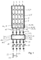
- FIG. 1 shows, in a schematic plan view, an antenna array 1 which, for example, comprises a large number of dual-polarized radiators or radiator elements 3, which are arranged in front of a reflector 5.
- a reflector belonging to the edge boundary 5 ' which is set up at right angles to the plane of the reflector sheet.
- these reflector edge boundaries 5 ' are positioned slightly obliquely outwards in the emission direction.
- the antenna array has four columns 7, which are arranged vertically, with four radiators or radiator groups 3 being arranged one above the other in each column in the exemplary embodiment shown.
- radiators or radiator groups 3 are positioned one above the other in the vertical direction.
- the individual radiators or radiator groups 3 need not necessarily be arranged in the same height in the individual columns.
- the radiators or radiator groups 3 it is possible, for example, for the radiators or radiator groups 3 to be two in each case adjacent columns 7 offset by half the vertical distance between two adjacent radiators to each other. Deviating from this, in the schematic plan view in FIG. 1, a representation is reproduced in which the radiators or radiator groups 3 in adjacent columns each come to rest on the same contour line.
- the radiators 3 can consist, for example, of cross-shaped dipole radiators or dipole squares.
- Particularly suitable dual polarized Dipolstrahler 3 ', as for example from the WO 00/39894 are known. Reference is made in its entirety to the disclosure content of this prior publication and made part of the content of this application.
- a beam forming network 17 which has, for example, four inputs 19 and four outputs 21.
- the four outputs of the beamforming network 17 are connected to the four inputs 15 of the antenna array.
- the number of outputs N may differ from the number of inputs n, ie in particular, the number of outputs N may be greater than the number of inputs n.
- a feed cable 23 is connected to one of the inputs 19, about all outputs 21 are fed accordingly.
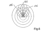
- a horizontal emitter orientation 16.1 be effected with, for example, -45 ° to the left, as can be seen from the schematic diagram of Figure 3. If, for example, the supply cable 23 is connected at the most right connection 19.4, then a corresponding Alignment 16.4 causes the main lobe 16 of the radiation field of the antenna array in an angle of + 45 ° to the right.
- the antenna array when the feeder cable 23 is connected to the terminal 19.2 or to the terminal 19.3, the antenna array is operated so that, for example, a pivoting 16.2, 16.3 causes by 15 ° to the left or to the right with respect to the vertical plane of symmetry of the antenna array can be, so in different azimuth direction.
- a beam forming network 17 it is common in such a beam forming network 17 to provide a corresponding number of inputs for different azimuth angular orientations of the main lobe 16 of the antenna array, wherein the number of outputs usually corresponds to the number of columns of the antenna array.
- Each input is connected to a plurality of outputs, usually each input to all outputs of the beam forming network 17.
- the beam-forming network 17 may, for example, be a known Butler matrix 17 'whose four inputs 19.1, 19.2, 19.3 and 19.4 are each connected to all outputs 21.1, 21.2, 21.3 and 21.4, via which the radiators are connected via lines 35 3 are fed.
- the feed cable 23 via a branching or summing 26 not only with an input, but at least two inputs or more of the inputs 19.1 to 19.4 to connect.
- a calibration of the Butler matrix and the connected antenna array must first be performed.
- This first requires the phase characteristic at the outputs 21.1 to 21.4 of the beam-forming network 17, preferably in the form of the Butler matrix 17 ', to be metered in response to feed of the feed signal once via the inputs 19.1, 19.2, 19.3 and 19.4 of the Butler matrix 17 '.
- the beam-forming network 17 Depending on the connected input 19.1 to 19.4, the beam-forming network 17 generates different radiation patterns in the form of the Butler matrix 17 'because of the different phase assignments of the dipoles or dipole rows, ie the radiators 3, 3'.
- the radiators 3, 3' For example, in the vertical arrangement of radiators 3, 3 'in the four columns 7 four different horizontal diagrams generated. The phase relationships of the radiators in the individual columns gives the diagram according to FIG. 4.
- a phase jump of, for example, 180 ° between the primary radiators 3, 3' of the different polarizations can occur.
- the measured curves (straight lines) reproduced in FIG. 4 must be changed in their position according to the arrow illustration 28 so that the two upper ones Traces in the form of straight lines 30 and 32 with the two in Figure 4 deeper and steeper extending traces 34 and 36 intersect at a common intersection X, as shown in Figure 5.
- phase actuators 37th take place, which are the inputs 19.1 to 19.4 of the Butler matrix 17 'upstream, so that inputs A to D result for the overall circuit.
- phase actuators 37 shown in FIG. 1 corresponding additional cable lengths can be connected in series at the individual inputs 19. 1 to 19. 4, whose length is dimensioned such that the desired phase shift is effected.
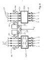
- intermediate lobes 116 can now be generated, as shown for example in the case of the diagram according to FIG. 6, in that the inputs 19.1 and 19.2 or 19.2 and 19.3 or 19.3 and 19.4 are connected together. Preferably, all inputs are supplied with the same power.
- FIG. 7 now shows the device for phase alignment of the supply lines, that is to say for carrying out a phase calibration.
- the phase actuators of the Butler matrix 17 'of the mentioned phase adjustment for the intermediate lobes 116 is performed so that they by combining the inputs A and B, B and C or C and D makes sense and without further action can be used on the antenna feeders.
- a suitable calibration signal i. given a known signal and measured at the output S of the combination network (Comb) the absolute phase. Now you can do this also for the supply lines to the inputs B, C and D.
- the couplers 111 are preferably connected between the respective output 21 and the respective input 15 of the associated column 7 of the antenna array.
- the couplers must be connected between the network accommodated in the Butler matrix 17 'and at least one emitter 3, 3' in an associated column 7 of the antenna array.
- FIG. 8 it is shown how to use an antenna with two polarizations, e.g. + 45 ° and -45 ° can combine the network for phase alignment of the supply lines.
- Such a combination makes sense if e.g. the Butler matrix can be realized together with the couplers and combination networks on a board, as this largely identical units (each coupler and combination networks) can be produced.
- the extension from the representation according to FIG. 7 is effected by combining the two outputs of the respective combination network 27 and 27 ', for example in the form of a combiner (Comb), with the inputs of a downstream second combination network 27 "likewise in the form of a combiner (Comb) and to the common output S.
- the combination network 27 thus serves to determine the phase position on a radiator element with respect to the one polarization, wherein the combination network 27 'is used to determine the phase position at a respective radiator for the other polarization.
- phase actuators may consist of basically vorschaltbaren cable sections to change the phase position.
- a coupler 111 for example in the form of a directional coupler on all four lines 35 in order to obtain even more measuring points to achieve the reproduced in the diagrams of Figures 4 and 5 straight lines.
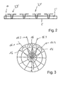
- probes 11 can be used, which are designed, for example, pin-shaped and preferably rise at right angles from the plane of the reflector sheet 5 and are assigned to a particular radiator 3.
- the probes 11 may preferably consist of capacitive coupling pins. But they can also be formed from inductively operating coupling loops. In both cases, the probes 11 protrude from the reflector into the near field of the radiator.
- the mentioned probes 11 can also be used for dual-polarized radiators 3 'since both polarizations can be measured via this. In FIG. 1, for example, for the left-hand column and the right-hand column, in each case the lowermost radiator 3, 3 'is associated with such a probe 11 and 11b shown in plan view.
- This probe is then used in place of the directional couplers 11 shown in FIGS. 7 and 8 to detect the signal measured thereon in a combination network 27 or in a combination network dual polarized antenna in a combination network 27 'and 27 "is shown in Figure 9.
- a combination network 27 is shown which operates with two probes 11, ie 11a and 11b.
- the combination networks are suitable for single polarized antennas. In principle, they are also suitable for a dual-polarized antenna array.
- probes 11 is suitable here, since a single probe suffices to be assigned to a dual-polarized emitter arrangement 3, 3 ', since the desired partial signals in both polarizations can ultimately be received via this one probe.
- a coupling device a coupling device would then have to be used for each polarization, that is, in the case of the dual-polarized antenna array, instead of a probe, a pair of coupling device would then become necessary.
Landscapes
- Variable-Direction Aerials And Aerial Arrays (AREA)
- Input Circuits Of Receivers And Coupling Of Receivers And Audio Equipment (AREA)
Claims (16)
- Dispositif de calibrage pour un réseau d'antennes, qui comprend au moins un réseau d'antennes (1) pourvu d'au moins deux colonnes verticales (7) comprenant chacune plusieurs éléments rayonneurs (3, 3') agencés les uns au-dessus des autres, des entrées (15) étant associées aux plusieurs colonnes (7) dans lesquelles sont agencés lesdits plusieurs éléments rayonneurs respectifs (3, 3'), entrées en amont desquelles est prévu un réseau de formation de rayon (17) dont les sorties (21) sont connectées chacune à une entrée associée (15) du réseau d'antennes, via laquelle sont alimentés les éléments rayonneurs (3, 3') prévus dans une colonne (7), le réseau de formation de rayon (17) génère, en fonction de l'entrée branchée (19.1 à 19.4), une autre relation de phase entre les éléments rayonneurs (3, 3') agencés dans les colonnes individuelles (7), afin d'obtenir différentes directions de rayonnement en direction azimutale, et au moins deux entrées (19.1, 19.2, 19.3, 19.4) sont alimentées via un câble d'alimentation commun (23) ou via des câbles d'alimentation séparés (23),
caractérisé par les autres éléments suivants :- le dispositif de calibrage comprend en outre au moins une sonde (11) qui est agencée dans le champ proche des éléments rayonneurs (3, 3') et/ou au moins un dispositif de couplage (111) qui est agencé en aval du réseau de formation de rayon (17),- le dispositif de calibrage comprend uniquement pour une partie des colonnes (7) au moins une sonde (11) ou au moins un dispositif de couplage (111) ou au moins une paire de dispositifs de couplage (111),- le dispositif de calibrage comprend en outre un dispositif d'étalonnage qui est agencé en amont des entrées (19) du réseau de formation de rayon (17 ; 17'), au moyen duquel le phasage des signaux amenés aux entrées (19) du réseau de formation de rayon (17 ; 17') est présélectionné en fonction des signaux de sortie de ladite au moins une sonde (11) ou dudit au moins un dispositif de couplage (111), et- au moyen du dispositif d'étalonnage ainsi formé, le phasage aux entrées du réseau de formation de rayon (17 ; 17') est présélectionnable ou modifiable de telle sorte qu'au moyen du réseau d'antennes (1), on peut générer, outre deux lobes intermédiaires situés au milieu entre deux lobes principaux, au choix également des lobes orientés dans différentes directions de rayonnement azimutales. - Dispositif de calibrage pour un réseau d'antennes commutable selon la revendication 1, caractérisé en ce que le dispositif d'étalonnage appartenant au dispositif de calibrage comprend des organes de réglage de phase (37) qui sont branchés en amont du réseau de formation de rayon (17 ; 17').
- Dispositif de calibrage pour un réseau d'antennes commutable selon la revendication 1, caractérisé en ce que des lignes supplémentaires sont agencées en amont des entrées sélectionnées individuellement (19.1, 19.2, 19.3, 19.4) à une longueur prédéterminée en avant du réseau de formation de rayon (17) ou sont branchées à ces entrées (19.1, 19.2, 19.3, 19.4).
- Dispositif de calibrage pour un réseau d'antennes commutable selon l'une des revendications 1 à 3, caractérisé en ce que les sondes (11) et/ou le dispositif de couplage (111) sont branchés à un réseau de calibrage (27, 27', 27").
- Dispositif de calibrage pour un réseau d'antennes commutable selon la revendication 4, caractérisé en ce qu'au moins une colonne (7) comprend une sonde (11) et de préférence au moins deux colonnes (7) comprennent chacune au moins une sonde (11) qui est ou sont associée(s) chacune à un élément rayonneur (3, 3'), via lesquelles un signal partiel (signaux de champ proche) est amené au réseau de calibrage (27, 27', 27") pendant la phase de calibrage, ce qui fixe l'étalonnage de phase.
- Dispositif de calibrage pour un réseau d'antennes commutable selon la revendication 4, caractérisé en ce qu'au moins un dispositif de couplage (111) est associé à au moins un élément rayonneur (3, 3') d'une colonne (7) ou au moins un dispositif de couplage respectif (111) est associé à au moins un élément rayonneur respectif (3, 3') de deux colonnes (7), via lequel un signal partiel (un signal découplé) est amené au réseau de calibrage (27, 27', 27") pendant la phase de calibrage, ce qui fixe l'étalonnage de phase.
- Dispositif de calibrage pour un réseau d'antennes commutable selon la revendication 6, caractérisé en ce que le dispositif de couplage (111) est agencé de préférence entre la sortie respective (21) du réseau de formation de rayon (17, 17') et l'entrée associée (15) du réseau d'antennes (1).
- Dispositif de calibrage pour un réseau d'antennes commutable selon l'une des revendications 1 à 7, caractérisé en ce que la sonde (11) ou les sondes (11) sont constituées par des sondes capacitives ou par une sonde (11) à fonctionnement inductif sous la forme d'une petite boucle d'induction.
- Dispositif de calibrage pour un réseau d'antennes commutable selon la revendication 6, caractérisé en ce que dans le cas d'un réseau d'antennes à polarisation double, au moins une colonne (7), de préférence au moins deux colonnes (7) sont pourvues chacune d'une paire de dispositifs de couplage (111), à savoir d'un dispositif de couplage respectif (111) pour une polarisation.
- Dispositif de calibrage selon l'une des revendications 1 à 9, caractérisé en ce que dans un réseau d'antennes à polarisation double, ladite une ou les plusieurs sondes prévues (11) conviennent chacune à recevoir un signal pour les deux polarisations.
- Dispositif de calibrage selon l'une des revendications 1 à 10, caractérisé en ce que pour chaque colonne (7), il est prévu une sonde (11) ou un dispositif de couplage (111) ou une paire de dispositifs de couplage (111) uniquement pour un élément rayonneur (3, 3').
- Dispositif de calibrage selon l'une des revendications 1 à 11, caractérisé en ce que par rapport aux éléments rayonneurs (3, 3') associés à ladite au moins une sonde (11) ou aux plusieurs sondes (11), celles-ci se trouvent sur un plan de symétrie vertical traversant les éléments rayonneurs (3, 3').
- Dispositif de calibrage selon l'une des revendications 1 à 12, caractérisé en ce que dans un réseau d'antennes comprenant quatre colonnes (7), il est prévu au moins deux sondes (11) qui sont agencées dans le champ proche d'un élément rayonneur respectif (3, 3') qui est agencé dans les deux colonnes extérieures (7) ou dans les deux colonnes intérieures (7) du réseau d'antennes.
- Dispositif de calibrage selon l'une des revendications 1 à 13, caractérisé en ce que dans un réseau d'antennes comprenant quatre colonnes (7), il est prévu au moins deux dispositifs de couplage (111) ou deux paires de dispositifs de couplage (111), ou encore deux paires de dispositifs de couplage (111) associés chacun à un élément rayonneur (3, 3'), qui sont agencés dans les deux colonnes extérieures ou dans les deux colonnes intérieures (7) du réseau d'antennes.
- Dispositif de calibrage selon l'une des revendications 1 à 14, caractérisé en ce que les sondes (11) sont agencées à la même ligne en hauteur.
- Dispositif de calibrage selon l'une des revendications 1 à 15, caractérisé en ce qu'il est prévu une sonde respective (11 ; 11c, 11d) pour deux colonnes voisines (7) d'un réseau d'antennes, sondes qui présentent de préférence le même amortissement de couplage.
Applications Claiming Priority (3)
| Application Number | Priority Date | Filing Date | Title |
|---|---|---|---|
| DE10237822 | 2002-08-19 | ||
| DE10237822A DE10237822B3 (de) | 2002-08-19 | 2002-08-19 | Kalibriereinrichtung für ein umschaltbares Antennen-Array sowie ein zugehöriges Betriebsverfahren |
| PCT/EP2003/005932 WO2004023601A1 (fr) | 2002-08-19 | 2003-06-05 | Dispositif de calibrage pour un reseau d'antennes commutable et procede pour faire fonctionner ce dispositif |
Publications (3)
| Publication Number | Publication Date |
|---|---|
| EP1530816A1 EP1530816A1 (fr) | 2005-05-18 |
| EP1530816B1 EP1530816B1 (fr) | 2006-06-07 |
| EP1530816B9 true EP1530816B9 (fr) | 2007-10-03 |
Family
ID=31501801
Family Applications (1)
| Application Number | Title | Priority Date | Filing Date |
|---|---|---|---|
| EP03740191A Expired - Lifetime EP1530816B9 (fr) | 2002-08-19 | 2003-06-05 | Dispositif de calibrage pour un reseau d'antennes commutable et procede pour faire fonctionner ce dispositif |
Country Status (9)
| Country | Link |
|---|---|
| US (1) | US7132979B2 (fr) |
| EP (1) | EP1530816B9 (fr) |
| KR (1) | KR100893656B1 (fr) |
| CN (1) | CN2800506Y (fr) |
| AT (1) | ATE329381T1 (fr) |
| AU (1) | AU2003297841A1 (fr) |
| DE (2) | DE10237822B3 (fr) |
| ES (1) | ES2263987T3 (fr) |
| WO (1) | WO2004023601A1 (fr) |
Families Citing this family (21)
| Publication number | Priority date | Publication date | Assignee | Title |
|---|---|---|---|---|
| US6970002B1 (en) | 2004-05-13 | 2005-11-29 | The United States Of America As Represented By The Secretary Of The Navy | Tube measurement and calibration system |
| US20060044183A1 (en) * | 2004-08-30 | 2006-03-02 | Wells Donald R | Low frequency radar antenna |
| CN101076923B (zh) * | 2004-12-13 | 2013-12-25 | 艾利森电话股份有限公司 | 天线装置及其相关方法 |
| EP1878206A4 (fr) * | 2005-04-25 | 2012-12-19 | Xocyst Transfer Ag L L C | Systemes et procedes de formation de faisceau |
| US7215298B1 (en) * | 2005-09-06 | 2007-05-08 | Lockheed Martin Corporation | Extendable/retractable antenna calibration element |
| KR100706614B1 (ko) * | 2005-09-29 | 2007-04-12 | 한국전자통신연구원 | 높은 격리도를 갖는 송수신 분리형 안테나 |
| US7847740B2 (en) * | 2006-02-13 | 2010-12-07 | Kyocera Corporation | Antenna system having receiver antenna diversity and configurable transmission antenna and method of management thereof |
| WO2008088859A2 (fr) * | 2007-01-18 | 2008-07-24 | Mobileaccess Networks Ltd. | Antenne à large bande hybride passive-active pour système d'antennes réparties |
| WO2008103374A2 (fr) * | 2007-02-19 | 2008-08-28 | Mobile Access Networks Ltd. | Procédé et système pour améliorer l'efficacité d'une liaison montante |
| KR101172240B1 (ko) * | 2010-05-18 | 2012-08-07 | 주식회사 만도 | 센서 및 얼라이먼트 조절 방법 |
| WO2013067657A1 (fr) * | 2011-11-11 | 2013-05-16 | Telefonaktiebolaget L M Ericsson (Publ) | Procédé, appareil et système de configuration dynamique d'un réseau d'antennes |
| BR112015010998B1 (pt) * | 2012-12-03 | 2022-02-08 | Telefonaktiebolaget Lm Ericsson (Publ) | Nó em uma rede de comunicação sem fio |
| US9300408B2 (en) * | 2013-11-04 | 2016-03-29 | Alcatel-Lucent Shanghai Bell Co., Ltd | Methods and systems for calibrating LTE antenna systems |
| DE102014011883A1 (de) | 2014-08-13 | 2016-02-18 | Tesat-Spacecom Gmbh & Co.Kg | Speisenetzwerkanordnung zum Generieren eines Mehrfachantennensignals |
| US9848370B1 (en) * | 2015-03-16 | 2017-12-19 | Rkf Engineering Solutions Llc | Satellite beamforming |
| WO2018007995A1 (fr) * | 2016-07-08 | 2018-01-11 | Magna Electronics Inc. | Système radar mimo 2d pour véhicule |
| CN106450796B (zh) * | 2016-09-07 | 2020-01-07 | 四川九洲电器集团有限责任公司 | 一种阵列天线系统及天线的校准方法 |
| US10571503B2 (en) * | 2018-01-31 | 2020-02-25 | Rockwell Collins, Inc. | Methods and systems for ESA metrology |
| US11114757B2 (en) * | 2018-08-31 | 2021-09-07 | Rockwell Collins, Inc. | Embedded antenna array metrology systems and methods |
| WO2022141165A1 (fr) * | 2020-12-30 | 2022-07-07 | 华为技术有限公司 | Procédé et système de calibrage d'antennes |
| EP4305707A1 (fr) * | 2021-03-11 | 2024-01-17 | Telefonaktiebolaget LM Ericsson (publ) | Système d'antenne active comprenant des trajets de couplage entre des réseaux d'alimentation |
Family Cites Families (35)
| Publication number | Priority date | Publication date | Assignee | Title |
|---|---|---|---|---|
| DE3788125T2 (de) | 1986-12-22 | 1994-06-09 | Hughes Aircraft Co | Steuerbare strahlungskeule eines antennensystems mit butler-matrix. |
| FR2672436B1 (fr) * | 1991-01-31 | 1993-09-10 | Europ Agence Spatiale | Dispositif de controle electronique du diagramme de rayonnement d'une antenne a un ou plusieurs faisceaux de direction et/ou de largeur variable. |
| US5086302A (en) * | 1991-04-10 | 1992-02-04 | Allied-Signal Inc. | Fault isolation in a Butler matrix fed circular phased array antenna |
| US5276452A (en) | 1992-06-24 | 1994-01-04 | Raytheon Company | Scan compensation for array antenna on a curved surface |
| FR2696553B1 (fr) | 1992-10-01 | 1994-11-25 | Alcatel Espace | Méthode de calibration d'antenne en champ proche pour antenne active. |
| US5502447A (en) | 1993-10-28 | 1996-03-26 | Hazeltine Corporation | Beam sharpened pencil beam antenna systems |
| US5644316A (en) | 1996-05-02 | 1997-07-01 | Hughes Electronics | Active phased array adjustment using transmit amplitude adjustment range measurements |
| US5784030A (en) * | 1996-06-06 | 1998-07-21 | Hughes Electronics Corporation | Calibration method for satellite communications payloads using hybrid matrices |
| FR2750258B1 (fr) | 1996-06-24 | 1998-08-21 | Europ Agence Spatiale | Systeme de conformation de faisceau zonal reconfigurable pour une antenne embarquee sur un satellite en orbite et procede d'optimisation de la reconfiguration |
| US5784031A (en) * | 1997-02-28 | 1998-07-21 | Wireless Online, Inc. | Versatile anttenna array for multiple pencil beams and efficient beam combinations |
| SE510995C2 (sv) | 1997-03-24 | 1999-07-19 | Ericsson Telefon Ab L M | Aktiv sändnings/mottagnings gruppantenn |
| US6104935A (en) * | 1997-05-05 | 2000-08-15 | Nortel Networks Corporation | Down link beam forming architecture for heavily overlapped beam configuration |
| SE509342C2 (sv) * | 1997-05-05 | 1999-01-18 | Ericsson Telefon Ab L M | Förfarande för användning av lobportar i ett lobformningsnät samt ett antennarrangemang |
| US5840032A (en) * | 1997-05-07 | 1998-11-24 | General Electric Company | Method and apparatus for three-dimensional ultrasound imaging using transducer array having uniform elevation beamwidth |
| SE509434C2 (sv) * | 1997-05-16 | 1999-01-25 | Ericsson Telefon Ab L M | Anordning och förfarande vid antennkalibrering |
| US6046697A (en) * | 1997-09-05 | 2000-04-04 | Northern Telecom Limited | Phase control of transmission antennas |
| US5936569A (en) * | 1997-12-02 | 1999-08-10 | Nokia Telecommunications Oy | Method and arrangement for adjusting antenna pattern |
| DE19806914C2 (de) | 1998-02-19 | 2002-01-31 | Bosch Gmbh Robert | Verfahren und Vorrichtung zum Kalibrieren einer Gruppenantenne |
| US6252542B1 (en) * | 1998-03-16 | 2001-06-26 | Thomas V. Sikina | Phased array antenna calibration system and method using array clusters |
| US6133868A (en) * | 1998-06-05 | 2000-10-17 | Metawave Communications Corporation | System and method for fully self-contained calibration of an antenna array |
| DE19844239C1 (de) * | 1998-09-26 | 2000-07-27 | Dornier Gmbh | Verfahren zur genauen Winkelbestimmung von Zielen mittels eines Mehrfachantennen-Radarsystems |
| US6157340A (en) * | 1998-10-26 | 2000-12-05 | Cwill Telecommunications, Inc. | Adaptive antenna array subsystem calibration |
| DE19860121A1 (de) * | 1998-12-23 | 2000-07-13 | Kathrein Werke Kg | Dualpolarisierter Dipolstrahler |
| US6515616B1 (en) * | 1999-04-30 | 2003-02-04 | Metawave Communications Corporation | System and method for aligning signals having different phases |
| US6236839B1 (en) * | 1999-09-10 | 2001-05-22 | Utstarcom, Inc. | Method and apparatus for calibrating a smart antenna array |
| SE518207C2 (sv) * | 1999-09-10 | 2002-09-10 | Ericsson Telefon Ab L M | Gles gruppantenn |
| JP4303373B2 (ja) * | 1999-09-14 | 2009-07-29 | 株式会社日立コミュニケーションテクノロジー | 無線基地局装置 |
| FR2800202B1 (fr) | 1999-10-26 | 2007-08-31 | Thomson Csf | Dispositif de commande pour la formation de plusieurs faisceaux simultanes de reception radar a antenne a balayage electronique |
| WO2001056186A2 (fr) * | 2000-01-27 | 2001-08-02 | Celletra, Ltd. | Systeme et procede d'adaptation de la polarisation dans une liaison aval de telecommunication cellulaire |
| SE522564C2 (sv) | 2000-02-01 | 2004-02-17 | Ericsson Telefon Ab L M | Gruppantennkalibrering |
| EP2474436A3 (fr) * | 2000-08-16 | 2012-07-25 | Valeo Radar Systems, Inc. | Architecture d'antenne à faisceau commuté |
| JP3923897B2 (ja) * | 2000-12-23 | 2007-06-06 | ノキア コーポレイション | 到来方向を推定するための基地局、基地局モジュールおよび方法 |
| US6680698B2 (en) | 2001-05-07 | 2004-01-20 | Rafael-Armament Development Authority Ltd. | Planar ray imaging steered beam array (PRISBA) antenna |
| US6426726B1 (en) | 2001-08-15 | 2002-07-30 | Northrop Grumman Corporation | Polarized phased array antenna |
| WO2003019722A1 (fr) | 2001-08-23 | 2003-03-06 | Paratek Microwave, Inc. | Procede d'etalonnage en champ proche pour antennes reseau a commande de phase comprenant des dephaseurs accordables |
-
2002
- 2002-08-19 DE DE10237822A patent/DE10237822B3/de not_active Expired - Fee Related
-
2003
- 2003-06-05 AT AT03740191T patent/ATE329381T1/de not_active IP Right Cessation
- 2003-06-05 ES ES03740191T patent/ES2263987T3/es not_active Expired - Lifetime
- 2003-06-05 WO PCT/EP2003/005932 patent/WO2004023601A1/fr not_active Application Discontinuation
- 2003-06-05 AU AU2003297841A patent/AU2003297841A1/en not_active Abandoned
- 2003-06-05 EP EP03740191A patent/EP1530816B9/fr not_active Expired - Lifetime
- 2003-06-05 KR KR1020057000142A patent/KR100893656B1/ko not_active IP Right Cessation
- 2003-06-05 DE DE50303722T patent/DE50303722D1/de not_active Expired - Lifetime
- 2003-06-06 US US10/455,801 patent/US7132979B2/en not_active Expired - Lifetime
- 2003-08-13 CN CNU032081340U patent/CN2800506Y/zh not_active Expired - Lifetime
Also Published As
| Publication number | Publication date |
|---|---|
| AU2003297841A1 (en) | 2004-03-29 |
| EP1530816B1 (fr) | 2006-06-07 |
| DE50303722D1 (de) | 2006-07-20 |
| US7132979B2 (en) | 2006-11-07 |
| EP1530816A1 (fr) | 2005-05-18 |
| ATE329381T1 (de) | 2006-06-15 |
| WO2004023601A1 (fr) | 2004-03-18 |
| US20040032366A1 (en) | 2004-02-19 |
| DE10237822B3 (de) | 2004-07-22 |
| KR20050033065A (ko) | 2005-04-08 |
| CN2800506Y (zh) | 2006-07-26 |
| KR100893656B1 (ko) | 2009-04-17 |
| ES2263987T3 (es) | 2006-12-16 |
Similar Documents
| Publication | Publication Date | Title |
|---|---|---|
| EP1530816B9 (fr) | Dispositif de calibrage pour un reseau d'antennes commutable et procede pour faire fonctionner ce dispositif | |
| EP1532716B1 (fr) | Dispositif d'etalonnage destine a un reseau d'antennes et procede d'etalonnage de ce reseau d'antennes | |
| EP1082781B1 (fr) | Reseau d'antennes a plusieurs modules excitateurs superposes | |
| EP2168211B1 (fr) | Réseau d'alimentation pour une antenne réseau | |
| DE3911373C2 (de) | Phasengesteuertes Radargerät mit Selbstüberwachung/Selbstabgleich und auswechselbare einstellbare Sende/Empfangs-Baueinheit | |
| DE10256960B3 (de) | Zweidimensionales Antennen-Array | |
| EP2929589B1 (fr) | Antenne omnidirectionnelle à double polarité | |
| DE60104270T2 (de) | Phasenschieber | |
| EP2965382B1 (fr) | Système d'antennes à caractéristique directionnelle variable | |
| DE202021106120U1 (de) | Strahlerelemente mit abgewinkelten Einspeiseschäften und Basisstationsantennen einschließlich derselben | |
| DE69831323T2 (de) | Kombination von butler-strahlungskeulenanschlüssen für hexagonale zellenbedeckung | |
| DE102013012305A1 (de) | Breitband-Antennenarray | |
| EP1525642B1 (fr) | Reseau d'antennes bidimensionnel | |
| EP2862234B1 (fr) | Système d'antennes actif | |
| DE102005011128B4 (de) | Kalibrierung einer elektronischen steuerbaren Planarantenne und elektronisch steuerbare Antenne mit einer Messsonde im reaktiven Nahfeld | |
| DE10336071B3 (de) | Antennenanordnung sowie Verfahren insbesondere zu deren Betrieb | |
| EP1652267B1 (fr) | Systeme d'antenne | |
| AT502159B1 (de) | Mikrostreifen-patchantenne und einpunkteinspeisung in diese antenne | |
| EP1471600B1 (fr) | Procéde de génération de multi-faisceaux de transmission de système SAR et système d'antenna de SAR | |
| DE102007055534B4 (de) | Kompakte Richtantennenanordnung mit Mehrfachnutzung von Strahlerelementen | |
| EP3625894A1 (fr) | Système de radio mobile comprenant un réseau de formation de faisceau et un système multi-antennes prévu pour générer un faisceau de diffusion et procédé correspondant | |
| DE4201933A1 (de) | Strahlergruppenantenne | |
| EP0227005A2 (fr) | Dispositif d'émission à deux émetteurs haute fréquence émettant des fréquences différentes avec des diagrammes de rayonnement différents | |
| WO1999031758A1 (fr) | Systeme d'alimentation d'antenne |
Legal Events
| Date | Code | Title | Description |
|---|---|---|---|
| PUAI | Public reference made under article 153(3) epc to a published international application that has entered the european phase |
Free format text: ORIGINAL CODE: 0009012 |
|
| 17P | Request for examination filed |
Effective date: 20041125 |
|
| AK | Designated contracting states |
Kind code of ref document: A1 Designated state(s): AT BE BG CH CY CZ DE DK EE ES FI FR GB GR HU IE IT LI LU MC NL PT RO SE SI SK TR |
|
| AX | Request for extension of the european patent |
Extension state: AL LT LV MK |
|
| 17Q | First examination report despatched |
Effective date: 20050624 |
|
| DAX | Request for extension of the european patent (deleted) | ||
| GRAP | Despatch of communication of intention to grant a patent |
Free format text: ORIGINAL CODE: EPIDOSNIGR1 |
|
| GRAS | Grant fee paid |
Free format text: ORIGINAL CODE: EPIDOSNIGR3 |
|
| GRAA | (expected) grant |
Free format text: ORIGINAL CODE: 0009210 |
|
| AK | Designated contracting states |
Kind code of ref document: B1 Designated state(s): AT BE BG CH CY CZ DE DK EE ES FI FR GB GR HU IE IT LI LU MC NL PT RO SE SI SK TR |
|
| PG25 | Lapsed in a contracting state [announced via postgrant information from national office to epo] |
Ref country code: IT Free format text: LAPSE BECAUSE OF FAILURE TO SUBMIT A TRANSLATION OF THE DESCRIPTION OR TO PAY THE FEE WITHIN THE PRESCRIBED TIME-LIMIT;WARNING: LAPSES OF ITALIAN PATENTS WITH EFFECTIVE DATE BEFORE 2007 MAY HAVE OCCURRED AT ANY TIME BEFORE 2007. THE CORRECT EFFECTIVE DATE MAY BE DIFFERENT FROM THE ONE RECORDED. Effective date: 20060607 Ref country code: RO Free format text: LAPSE BECAUSE OF FAILURE TO SUBMIT A TRANSLATION OF THE DESCRIPTION OR TO PAY THE FEE WITHIN THE PRESCRIBED TIME-LIMIT Effective date: 20060607 Ref country code: CZ Free format text: LAPSE BECAUSE OF FAILURE TO SUBMIT A TRANSLATION OF THE DESCRIPTION OR TO PAY THE FEE WITHIN THE PRESCRIBED TIME-LIMIT Effective date: 20060607 Ref country code: SI Free format text: LAPSE BECAUSE OF FAILURE TO SUBMIT A TRANSLATION OF THE DESCRIPTION OR TO PAY THE FEE WITHIN THE PRESCRIBED TIME-LIMIT Effective date: 20060607 Ref country code: NL Free format text: LAPSE BECAUSE OF FAILURE TO SUBMIT A TRANSLATION OF THE DESCRIPTION OR TO PAY THE FEE WITHIN THE PRESCRIBED TIME-LIMIT Effective date: 20060607 Ref country code: FI Free format text: LAPSE BECAUSE OF FAILURE TO SUBMIT A TRANSLATION OF THE DESCRIPTION OR TO PAY THE FEE WITHIN THE PRESCRIBED TIME-LIMIT Effective date: 20060607 Ref country code: SK Free format text: LAPSE BECAUSE OF FAILURE TO SUBMIT A TRANSLATION OF THE DESCRIPTION OR TO PAY THE FEE WITHIN THE PRESCRIBED TIME-LIMIT Effective date: 20060607 |
|
| REG | Reference to a national code |
Ref country code: GB Ref legal event code: FG4D Free format text: NOT ENGLISH |
|
| REG | Reference to a national code |
Ref country code: CH Ref legal event code: EP |
|
| REG | Reference to a national code |
Ref country code: IE Ref legal event code: FG4D Free format text: LANGUAGE OF EP DOCUMENT: GERMAN |
|
| REF | Corresponds to: |
Ref document number: 50303722 Country of ref document: DE Date of ref document: 20060720 Kind code of ref document: P |
|
| PG25 | Lapsed in a contracting state [announced via postgrant information from national office to epo] |
Ref country code: DK Free format text: LAPSE BECAUSE OF FAILURE TO SUBMIT A TRANSLATION OF THE DESCRIPTION OR TO PAY THE FEE WITHIN THE PRESCRIBED TIME-LIMIT Effective date: 20060907 |
|
| REG | Reference to a national code |
Ref country code: SE Ref legal event code: TRGR |
|
| PG25 | Lapsed in a contracting state [announced via postgrant information from national office to epo] |
Ref country code: PT Free format text: LAPSE BECAUSE OF FAILURE TO SUBMIT A TRANSLATION OF THE DESCRIPTION OR TO PAY THE FEE WITHIN THE PRESCRIBED TIME-LIMIT Effective date: 20061107 |
|
| NLV1 | Nl: lapsed or annulled due to failure to fulfill the requirements of art. 29p and 29m of the patents act | ||
| ET | Fr: translation filed | ||
| REG | Reference to a national code |
Ref country code: ES Ref legal event code: FG2A Ref document number: 2263987 Country of ref document: ES Kind code of ref document: T3 |
|
| GBT | Gb: translation of ep patent filed (gb section 77(6)(a)/1977) |
Effective date: 20061123 |
|
| PLBE | No opposition filed within time limit |
Free format text: ORIGINAL CODE: 0009261 |
|
| STAA | Information on the status of an ep patent application or granted ep patent |
Free format text: STATUS: NO OPPOSITION FILED WITHIN TIME LIMIT |
|
| 26N | No opposition filed |
Effective date: 20070308 |
|
| BERE | Be: lapsed |
Owner name: KATHREIN-WERKE K.G. Effective date: 20070630 |
|
| PG25 | Lapsed in a contracting state [announced via postgrant information from national office to epo] |
Ref country code: MC Free format text: LAPSE BECAUSE OF NON-PAYMENT OF DUE FEES Effective date: 20070630 |
|
| REG | Reference to a national code |
Ref country code: CH Ref legal event code: PL |
|
| PG25 | Lapsed in a contracting state [announced via postgrant information from national office to epo] |
Ref country code: BE Free format text: LAPSE BECAUSE OF NON-PAYMENT OF DUE FEES Effective date: 20070630 |
|
| PG25 | Lapsed in a contracting state [announced via postgrant information from national office to epo] |
Ref country code: CH Free format text: LAPSE BECAUSE OF NON-PAYMENT OF DUE FEES Effective date: 20070630 Ref country code: GR Free format text: LAPSE BECAUSE OF FAILURE TO SUBMIT A TRANSLATION OF THE DESCRIPTION OR TO PAY THE FEE WITHIN THE PRESCRIBED TIME-LIMIT Effective date: 20060908 Ref country code: LI Free format text: LAPSE BECAUSE OF NON-PAYMENT OF DUE FEES Effective date: 20070630 |
|
| PG25 | Lapsed in a contracting state [announced via postgrant information from national office to epo] |
Ref country code: BG Free format text: LAPSE BECAUSE OF FAILURE TO SUBMIT A TRANSLATION OF THE DESCRIPTION OR TO PAY THE FEE WITHIN THE PRESCRIBED TIME-LIMIT Effective date: 20060907 |
|
| PG25 | Lapsed in a contracting state [announced via postgrant information from national office to epo] |
Ref country code: EE Free format text: LAPSE BECAUSE OF FAILURE TO SUBMIT A TRANSLATION OF THE DESCRIPTION OR TO PAY THE FEE WITHIN THE PRESCRIBED TIME-LIMIT Effective date: 20060607 |
|
| PG25 | Lapsed in a contracting state [announced via postgrant information from national office to epo] |
Ref country code: AT Free format text: LAPSE BECAUSE OF NON-PAYMENT OF DUE FEES Effective date: 20070605 |
|
| PG25 | Lapsed in a contracting state [announced via postgrant information from national office to epo] |
Ref country code: CY Free format text: LAPSE BECAUSE OF FAILURE TO SUBMIT A TRANSLATION OF THE DESCRIPTION OR TO PAY THE FEE WITHIN THE PRESCRIBED TIME-LIMIT Effective date: 20060607 Ref country code: LU Free format text: LAPSE BECAUSE OF NON-PAYMENT OF DUE FEES Effective date: 20070605 |
|
| PG25 | Lapsed in a contracting state [announced via postgrant information from national office to epo] |
Ref country code: TR Free format text: LAPSE BECAUSE OF FAILURE TO SUBMIT A TRANSLATION OF THE DESCRIPTION OR TO PAY THE FEE WITHIN THE PRESCRIBED TIME-LIMIT Effective date: 20060607 Ref country code: HU Free format text: LAPSE BECAUSE OF FAILURE TO SUBMIT A TRANSLATION OF THE DESCRIPTION OR TO PAY THE FEE WITHIN THE PRESCRIBED TIME-LIMIT Effective date: 20061208 |
|
| PGFP | Annual fee paid to national office [announced via postgrant information from national office to epo] |
Ref country code: GB Payment date: 20150623 Year of fee payment: 13 |
|
| PGFP | Annual fee paid to national office [announced via postgrant information from national office to epo] |
Ref country code: IE Payment date: 20150622 Year of fee payment: 13 |
|
| REG | Reference to a national code |
Ref country code: FR Ref legal event code: PLFP Year of fee payment: 14 |
|
| PGFP | Annual fee paid to national office [announced via postgrant information from national office to epo] |
Ref country code: ES Payment date: 20160622 Year of fee payment: 14 |
|
| PGFP | Annual fee paid to national office [announced via postgrant information from national office to epo] |
Ref country code: FR Payment date: 20160621 Year of fee payment: 14 |
|
| GBPC | Gb: european patent ceased through non-payment of renewal fee |
Effective date: 20160605 |
|
| REG | Reference to a national code |
Ref country code: IE Ref legal event code: MM4A |
|
| PG25 | Lapsed in a contracting state [announced via postgrant information from national office to epo] |
Ref country code: IE Free format text: LAPSE BECAUSE OF NON-PAYMENT OF DUE FEES Effective date: 20160605 Ref country code: GB Free format text: LAPSE BECAUSE OF NON-PAYMENT OF DUE FEES Effective date: 20160605 |
|
| REG | Reference to a national code |
Ref country code: FR Ref legal event code: ST Effective date: 20180228 |
|
| PG25 | Lapsed in a contracting state [announced via postgrant information from national office to epo] |
Ref country code: FR Free format text: LAPSE BECAUSE OF NON-PAYMENT OF DUE FEES Effective date: 20170630 |
|
| REG | Reference to a national code |
Ref country code: DE Ref legal event code: R082 Ref document number: 50303722 Country of ref document: DE Representative=s name: FLACH BAUER & PARTNER PATENTANWAELTE MBB, DE Ref country code: DE Ref legal event code: R082 Ref document number: 50303722 Country of ref document: DE Representative=s name: FLACH BAUER STAHL PATENTANWAELTE PARTNERSCHAFT, DE |
|
| REG | Reference to a national code |
Ref country code: DE Ref legal event code: R081 Ref document number: 50303722 Country of ref document: DE Owner name: ERICSSON AB, SE Free format text: FORMER OWNER: KATHREIN-WERKE KG, 83022 ROSENHEIM, DE Ref country code: DE Ref legal event code: R081 Ref document number: 50303722 Country of ref document: DE Owner name: TELEFONAKTIEBOLAGET LM ERICSSON (PUBL), SE Free format text: FORMER OWNER: KATHREIN-WERKE KG, 83022 ROSENHEIM, DE Ref country code: DE Ref legal event code: R082 Ref document number: 50303722 Country of ref document: DE Representative=s name: FLACH BAUER STAHL PATENTANWAELTE PARTNERSCHAFT, DE Ref country code: DE Ref legal event code: R081 Ref document number: 50303722 Country of ref document: DE Owner name: KATHREIN SE, DE Free format text: FORMER OWNER: KATHREIN-WERKE KG, 83022 ROSENHEIM, DE |
|
| REG | Reference to a national code |
Ref country code: ES Ref legal event code: FD2A Effective date: 20181112 |
|
| PG25 | Lapsed in a contracting state [announced via postgrant information from national office to epo] |
Ref country code: ES Free format text: LAPSE BECAUSE OF NON-PAYMENT OF DUE FEES Effective date: 20170606 |
|
| REG | Reference to a national code |
Ref country code: DE Ref legal event code: R081 Ref document number: 50303722 Country of ref document: DE Owner name: ERICSSON AB, SE Free format text: FORMER OWNER: KATHREIN SE, 83022 ROSENHEIM, DE Ref country code: DE Ref legal event code: R082 Ref document number: 50303722 Country of ref document: DE Representative=s name: FLACH BAUER STAHL PATENTANWAELTE PARTNERSCHAFT, DE Ref country code: DE Ref legal event code: R081 Ref document number: 50303722 Country of ref document: DE Owner name: TELEFONAKTIEBOLAGET LM ERICSSON (PUBL), SE Free format text: FORMER OWNER: KATHREIN SE, 83022 ROSENHEIM, DE |
|
| REG | Reference to a national code |
Ref country code: DE Ref legal event code: R082 Ref document number: 50303722 Country of ref document: DE Representative=s name: FLACH BAUER STAHL PATENTANWAELTE PARTNERSCHAFT, DE Ref country code: DE Ref legal event code: R081 Ref document number: 50303722 Country of ref document: DE Owner name: TELEFONAKTIEBOLAGET LM ERICSSON (PUBL), SE Free format text: FORMER OWNER: ERICSSON AB, STOCKHOLM, SE |
|
| PGFP | Annual fee paid to national office [announced via postgrant information from national office to epo] |
Ref country code: SE Payment date: 20220627 Year of fee payment: 20 |
|
| PGFP | Annual fee paid to national office [announced via postgrant information from national office to epo] |
Ref country code: DE Payment date: 20220629 Year of fee payment: 20 |
|
| REG | Reference to a national code |
Ref country code: DE Ref legal event code: R071 Ref document number: 50303722 Country of ref document: DE |
|
| REG | Reference to a national code |
Ref country code: SE Ref legal event code: EUG |