EP0584635B1 - Device for obtaining the aperture configuration of a phased array antenna - Google Patents
Device for obtaining the aperture configuration of a phased array antenna Download PDFInfo
- Publication number
- EP0584635B1 EP0584635B1 EP93112787A EP93112787A EP0584635B1 EP 0584635 B1 EP0584635 B1 EP 0584635B1 EP 93112787 A EP93112787 A EP 93112787A EP 93112787 A EP93112787 A EP 93112787A EP 0584635 B1 EP0584635 B1 EP 0584635B1
- Authority
- EP
- European Patent Office
- Prior art keywords
- signal
- monitor
- additional
- integral
- waveguide
- Prior art date
- Legal status (The legal status is an assumption and is not a legal conclusion. Google has not performed a legal analysis and makes no representation as to the accuracy of the status listed.)
- Expired - Lifetime
Links
Images

Classifications
-
- H—ELECTRICITY
- H01—ELECTRIC ELEMENTS
- H01Q—ANTENNAS, i.e. RADIO AERIALS
- H01Q3/00—Arrangements for changing or varying the orientation or the shape of the directional pattern of the waves radiated from an antenna or antenna system
- H01Q3/26—Arrangements for changing or varying the orientation or the shape of the directional pattern of the waves radiated from an antenna or antenna system varying the relative phase or relative amplitude of energisation between two or more active radiating elements; varying the distribution of energy across a radiating aperture
- H01Q3/267—Phased-array testing or checking devices
Landscapes
- Variable-Direction Aerials And Aerial Arrays (AREA)
Description
Die Erfindung betrifft eine Einrichtung gemäß dem Oberbegriff des Patentanspruchs 1.The invention relates to a device according to the preamble of
Eine solche Einrichtung ist sowohl aus der DE-OS 40 12 101 A1 als auch aus der US-PS 4 926 186 bekannt. Sie wird z.B. zur Überwachung von phasengesteuerten Gruppenantennen in Mikrowellen-Landesystemen (MLS-Systemen) eingesetzt.Such a device is known both from DE-OS 40 12 101 A1 and from US Pat. No. 4,926,186. It will e.g. used to monitor phase-controlled group antennas in microwave landing systems (MLS systems).
In MLS-Systemen ist es aus Sicherheitsgründen wichtig, das einwandfreie Arbeiten der Sendevorrichtungen, insbesondere auch die Funktion der einzelnen Antennenelemente der Gruppenantennen, ständig zu überwachen. Dies geschieht in älteren MLS-Anlagen z.B. durch Überwachung von Strömen, die durch den einzelnen Antennenelementen als Phasenschieber vorgeschaltete PIN-Dioden fließen.For safety reasons, it is important in MLS systems to constantly monitor the correct functioning of the transmission devices, in particular also the function of the individual antenna elements of the group antennas. This happens in older MLS systems e.g. by monitoring currents flowing through the PIN diodes upstream of the individual antenna elements as phase shifters.
In den in den oben genannten Druckschriften beschriebenen Vorrichtungen wird, zusätzlich zu dieser Diodenstromüberwachung, der Verlauf des Antennenfernfeldes überwacht. Da das Antennenfernfeld mit der Aperturbelegung der Antenne über eine Fourier-Transformation verknüpft ist, lassen sich durch Überwachung des Fernfeldes neben Abweichungen in der Phasenbelegung auch Abweichungen in der Amplitudenbelegung der einzelnen Antennenelemente erkennen.In the devices described in the above-mentioned documents, in addition to this diode current monitoring, the course of the antenna far field is monitored. Since the antenna far field is linked to the aperture assignment of the antenna via a Fourier transformation, monitoring the far field not only allows deviations in the phase assignment but also deviations in the Detect the amplitude assignment of the individual antenna elements.
Der Verlauf des Fernfeldes einer phasengesteuerten Gruppenantenne läßt sich außer durch direkte Feldmessungen auch mittels eines sogenannten Integralmonitorhohlleiters erfassen, einem Hohlleiterbauelement, das parallel zur Gruppenachse der Antenne in der Nähe der Antennenelemente (Strahler) angeordnet und mit den Strahlungsfeldern der einzelnen Antennenelemente über Koppelöffnungen gekoppelt ist. In einem solchen Integralmonitorhohlleiter überlagern sich die von den einzelnen Antennenelementen stammenden Feldanteile zu einem Monitorsignal, das einem Ausgang des Integralmonitorhohlleiters entnommen werden kann und dessen Verlauf bei ausreichend großem Schwenkbereich der Antennenkeule bis auf einen Winkelversatz gegenüber der Senkrechten zur Antennengruppenachse, dem sogenannten Monitorwinkel oder Beobachtungswinkel, in guter Näherung dem Fernfelddiagramm entspricht.The course of the far field of a phase-controlled group antenna can be recorded in addition to direct field measurements using a so-called integral monitor waveguide, a waveguide component that is arranged parallel to the group axis of the antenna in the vicinity of the antenna elements (radiators) and is coupled to the radiation fields of the individual antenna elements via coupling openings. In such an integral monitor waveguide, the field components originating from the individual antenna elements overlap to form a monitor signal, which can be taken from an output of the integral monitor waveguide and whose course, with a sufficiently large swivel range of the antenna lobe, except for an angular offset with respect to the perpendicular to the antenna group axis, the so-called monitor angle or observation angle, corresponds to the far field diagram in a good approximation.
Der Beobachtungswinkel, um den das Monitorsignal gegenüber der Senkrechten der Antennengruppenachse versetzt ist, läßt sich in gewissen Grenzen durch die Abmessungen des Integralmonitorhohlleiters und durch die Gestaltung der Koppelöffnungen beeinflussen. Er kann bei der Berechnung der Aperturbelegung der Antenne berücksichtigt werden, so daß diese Berechnung, trotz Versatzes des Monitorsignals um den Beobachtungswinkel aus diesem Monitorsignal mittels Fourier-Transformation erfolgen kann.The observation angle by which the monitor signal is offset from the vertical of the antenna group axis can be influenced within certain limits by the dimensions of the integral monitor waveguide and by the design of the coupling openings. It can be taken into account when calculating the aperture assignment of the antenna, so that this calculation can be carried out from this monitor signal by means of a Fourier transformation, despite the monitor signal being offset by the observation angle.
Voraussetzung für eine gute Übereinstimmung des aus dem Integralmonitorhohlleiter gewonnenen Monitorsignals mit dem Fernfelddiagramm der Antenne und damit Voraussetzung für eine richtige Berechnung der Aperturbelegung der Antenne ist, daß die Antenne über einen ausreichend großen Winkelbereich hinweg geschwenkt wird. Dieser Winkelbereich sollte wenigstens eine volle Periode des Fernfelddiagrammes abdecken, damit zur Ausführung der Fourier-Transformation Feldinformation von einer ganzen Periode des Fernfelddiagramms zur Verfügung steht.A prerequisite for a good match of the monitor signal obtained from the integral monitor waveguide with the far field diagram of the antenna and thus a prerequisite for a correct calculation of the aperture assignment of the antenna is that the antenna is pivoted over a sufficiently large angular range. This angular range should cover at least one full period of the far field diagram, so that the Fourier transform field information from an entire period of the far field diagram is available.
In den meisten Fällen besitzen MLS-Antennen jedoch einen eingeschränkten Schwenkbereich, der oft nur einen Bruchteil einer Periode des Fernfelddiagrammes umfaßt. Die Ausführung der Fourier-Transformation des Monitorsignals wird in solchen Fällen fehlerhaft und damit unbrauchbar. Eine in der oben genannten US-PS, in Spalte 9, Zeile 34-42 vorgeschlagene Korrektur von durch einen zu engen Schwenkbereich hervorgerufenen Störungen durch Fensterung schafft keine grundsätzliche Abhilfe und ist allenfalls dann nützlich, wenn der Schwenkbereich nur sehr wenig kleiner als eine Periode des Fernfelddiagrammes ist.In most cases, however, MLS antennas have a restricted swivel range, which often only covers a fraction of a period of the far field diagram. In such cases, the execution of the Fourier transform of the monitor signal becomes faulty and therefore unusable. A correction proposed in the above-mentioned US-PS, column 9, lines 34-42, of disturbances caused by fenestration caused by a too narrow swivel range does not provide a fundamental remedy and is useful at most if the swivel range is only very little less than a period of Far field diagram is.
Es ist deshalb Aufgabe der Erfindung, eine Einrichtung gemäß dem Oberbegriff des Patentanspruchs 1 derart weiterzubilden, daß eine ausreichend genaue Berechnung der Aperturbelegung einer phasengesteuerten Gruppenantenne unter Verwendung eines Integralmonitorhohlleiters auch bei Antennen mit stark eingeschränktem Schwenkbereich möglich ist.It is therefore an object of the invention to develop a device according to the preamble of
Diese Aufgabe wird durch die Merkmale des Patentanspruchs 1 gelöst.This object is achieved by the features of
Durch den von dem ersten Ausgang räumlich getrennt vorgesehenen zweiten Ausgang des Integralmonitorhohlleiters und die zusätzliche Auswertung des dort entnommenen Monitorsignals wird der für die Berechnung der Aperturbelegung benötigte Schwenkbereich im günstigsten Falle auf das Doppelte erweitert. Werden die beiden Ausgänge z.B. an beiden Enden des Integralmonitorhohlleiters vorgesehen, wie im Patentanspruch 2 beansprucht, so liefert der erste Ausgang ein Monitorsignal, das nur Information aus einem der Breite des Schwenkbereiches entsprechenden Teilbereich des gesamten Fernfelddiagrammes enthält. Die Lage dieses Information liefernden, d.h. "sichtbaren" Bereiches innerhalb des Fernfelddiagrammes ist durch den Beobachtungswinkel θ bestimmt. Der zweite Ausgang am anderen Ende des Integralmonitorhohlleiters liefert ein Monitorsignal, das ebenfalls nur Information aus einem der Breite des Schwenkbereiches entsprechenden Teilbereich des Fernfelddiagrammes enthält. Dieser Teilbereich ist aber unter einem anderen Beobachtungswinkel, und zwar dem spiegelbildlich zu 0°, zur Mittelsenkrechten auf der Antennengruppenachse gelegenen Winkel -θ sichtbar. Bei nicht zu eingeschränktem Schwenkbereich ist es nun möglich, die an beiden Ausgängen gewonnenen Monitorsignale oder deren aufbereitete Signalteile einander ergänzend zu verwerten. Lassen sich die sichtbaren Teilbereiche in ihrer Lage und Breite so einstellen, daß sie zusammen eine Periode des Fernfelddiagrammes abdecken, so kann eine genaue Berechnung der Aperturbelegung der Antenne durchgeführt werden. In extremen Fällen, z.B. bei MLS-Elevationsantennen ist der Schwenkbereich so stark begrenzt (z.B. nur 15°), daß selbst durch zusätzliche Auswertung des aus einem zweiten Ausgang des Integralmonitorhohlleiters gewonnenen Monitorsignals kein einer vollen Periode des Fernfelddiagrammes entsprechender sichtbarer Bereich zusammengesetzt werden kann.Due to the second output of the integral monitor waveguide, which is spatially separated from the first output, and the additional evaluation of the monitor signal extracted there, the swivel range required for the calculation of the aperture assignment is expanded in the best case to double. If the two outputs are provided, for example, at both ends of the integral monitor waveguide, as claimed in claim 2, the first output delivers a monitor signal which only contains information from a partial area of the entire far field diagram corresponding to the width of the swivel area. The location of this information-providing, ie "visible" area within the far field diagram is determined by the observation angle θ. The second output at the other end of the integral monitor waveguide supplies a monitor signal which likewise only contains information from a partial area of the far field diagram corresponding to the width of the swivel area. However, this sub-area is visible at a different observation angle, namely the mirror-angle 0 to the central perpendicular to the antenna group axis. If the swivel range is not too limited, it is now possible to use the monitor signals obtained at both outputs or their processed signal parts in addition to each other. If the position and width of the visible subareas can be adjusted in such a way that they cover a period of the far field diagram, then an exact calculation of the aperture assignment of the antenna can be carried out. In extreme cases, e.g. with MLS elevation antennas, the swivel range is so limited (e.g. only 15 °) that even by additional evaluation of the monitor signal obtained from a second output of the integral monitor waveguide, no visible area corresponding to a full period of the far field diagram can be put together.
In diesem Falle können gemäß einer in Patentanspruch 3 beschriebenen Weiterbildung der Erfindung ein oder mehrere weitere Signalmonitorhohlleiter eingesetzt werden, deren Monitorwinkel so eingestellt sind, daß die zugeordneten sichtbaren Bereiche des Fernfelddiagrammes insgesamt die durch die sichtbaren Bereiche des ersten Integralmonitorhohlleiters nicht erfaßten Winkelbereiche einer Periode überdecken.In this case, according to a development of the invention described in claim 3, one or more further signal monitor waveguides can be used, the monitor angles of which are set such that the assigned visible areas of the far field diagram cover the angular ranges of a period not covered by the visible areas of the first integral monitor waveguide.
Anhand mehrerer Figuren sollen nun Ausführungsbeispiele der Einrichtung nach der Erfindung beschrieben werden.
- Fig. 1
- zeigt schematisch eine Einrichtung zur Gewinnung der Aperturbelegung nach dem Stand der Technik
- Fig. 2
- zeigt ein mit der in Fig. 1 dargestellten Einrichtung gewonnenes Monitorsignal
- Fig. 3
- zeigt schematisch eine Einrichtung zur Gewinnung der Aperturbelegung nach der Erfindung
- Fig. 4
- zeigt mit der Einrichtung nach Fig. 3 gewonnene Monitorsignale
- Fig. 5
- zeigt schematisch eine weitere Einrichtung nach der Erfindung
- Fig. 6
- zeigt ein aus vier Monitorsignalen zusammengesetztes Gesamt-Monitorsignal
- Fig. 1
- schematically shows a device for obtaining the aperture assignment according to the prior art
- Fig. 2
- shows a monitor signal obtained with the device shown in FIG. 1
- Fig. 3
- schematically shows a device for obtaining the aperture assignment according to the invention
- Fig. 4
- shows with the device of FIG. 3 obtained monitor signals
- Fig. 5
- shows schematically a further device according to the invention
- Fig. 6
- shows an overall monitor signal composed of four monitor signals
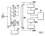
In Fig. 1 ist schematisch eine Einrichtung zur Gewinnung der Aperturbelegung einer MLS-Gruppenantenne dargestellt, wie sie aus dem Stand der Technik bekannt ist. Ein Sender S speist über ein Netzwerk N eine Anzahl von Antennenelementen (Strahlern) SE1...SEn. Die Zuführung der Hochfrequenzenergie zu den Antennenelementen erfolgt über den einzelnen Antennenelementen vorgeschaltete Phasenschieber PS1...PSn, in der Regel PIN-Dioden, die von einer Strahlsteuereinheit SST zu individuell vorgegebenen Zeiten angesteuert werden und jeweils eine vorgegebene Phasenverschiebung einstellen.
In Strahlernähe ist parallel zur Gruppenachse der Antenne ein Integralmonitorhohlleiter MH angeordnet, der auf Höhe der einzelnen Strahler je eine in der Figur nicht dargestellte Koppelöffnung besitzt und dessen Ausgang A über eine Signalaufbereitungsschaltung SAB und einen nachgeschalteten Analog/Digitalumsetzer AD mit einer Signalverarbeitungsschaltung SV verbunden ist. Die Signalverarbeitungsschaltung enthält einen schnellen Signalprozessor, der in der Lage ist, mathematische Operationen wie z.B. Fast-Fourier-Transformationen in Echtzeit auszuführen.1 schematically shows a device for obtaining the aperture assignment of an MLS array antenna, as is known from the prior art. A transmitter S feeds a number of antenna elements (radiators) SE1 ... SEn via a network N. The high-frequency energy is supplied to the antenna elements via phase shifters PS1 ... PSn upstream of the individual antenna elements, usually PIN diodes, which are controlled by a beam control unit SST at individually predetermined times and each set a predetermined phase shift.
An integral monitor waveguide MH is arranged in the vicinity of the radiator, parallel to the group axis of the antenna, which has a coupling opening (not shown in the figure) at the level of the individual radiators and whose output A is connected to a signal processing circuit SV via a signal conditioning circuit SAB and a downstream analog / digital converter AD. The signal processing circuit contains a fast signal processor which is capable of performing mathematical operations such as Fast Fourier transforms in real time.
Die in Fig. 1 dargestellte bekannte Einrichtung wertet ein Monitorsignal aus, das in Fig. 2 wiedergegeben ist. Dieses Signal entsteht im Integralmonitorhohlleiter MH durch Überlagerung der von den einzelnen Antennenelementen stammenden, über die Koppelöffnungen in den Hohlleiter eingekoppelten, mit unterschiedlichen Phasenverschiebungen behafteten Anteile des MLS-Sendesignals. Das dem Ausgang A entnommene Monitorsignal entspricht bis auf einen Winkelversatz gegenüber der Senkrechten auf der Antennengruppenachse, dem Beobachtungswinkel θM, dem Fernfelddiagramm der MLS-Antenne. Wie aus dem Fernfelddiagramm kann somit auch aus diesem Monitorsignal mittels einer Fourier-Transformation die Aperturbelegung der Antenne berechnet werden und vorgegebene Prüfwerte können zur Überwachung der einwandfreien Funktion der Sendeeinrichtung mit abgespeicherten Sollwerten verglichen werden. Verschiedene Verfahren zur Signalaufbereitung und Berechnung der Aperturbelegung sind in der eingangs genannten DE-OS 40 12 101 beschrieben.The known device shown in FIG. 1 evaluates a monitor signal, which is shown in FIG. 2. This signal is generated in the integral monitor waveguide MH by superimposing the portions of the MLS transmission signal which come from the individual antenna elements and which are coupled into the waveguide via the coupling openings and which have different phase shifts. The monitor signal taken from output A corresponds to the far field diagram of the MLS antenna except for an angular offset with respect to the vertical on the antenna group axis, the observation angle θ M. As in the far field diagram, the aperture assignment of the antenna can thus be calculated from this monitor signal by means of a Fourier transformation, and predetermined test values can be compared with stored setpoints to monitor the proper functioning of the transmitter. Various methods for signal processing and calculation of the aperture assignment are described in the aforementioned DE-OS 40 12 101.
Zur Berechnung der Aperturbelegung aus dem Fernfelddiagramm oder dem mittels Integralmonitorhohlleiter gewonnenen Monitorsignal über eine Fourier-Transformation ist es erforderlich, daß von mindestens einer ganzen Periode des Fernfeldes oder eines diesem entsprechenden Monitorsignals Meßwerte bzw. Abtastwerte zur Verfügung stehen. Letzteres ist dann nicht der Fall, wenn der Schwenkbereich der Antenne nur einen Winkelbereich umfaßt, der kleiner als der von einer Periode des Fernfelddiagrammes eingenommene Winkelbereich ist. Die über eine Fourier-Transformation berechnete Aperturbelegung entspricht dann nicht deren wirklichem Verlauf und ist damit unbrauchbar.To calculate the aperture assignment from the far field diagram or the monitor signal obtained by means of an integral monitor waveguide using a Fourier transformation, it is necessary that measured values or sampled values are available from at least one entire period of the far field or a monitor signal corresponding thereto. The latter is not the case if the swivel range of the antenna comprises only an angular range that is smaller than the angular range occupied by a period of the far field diagram. The aperture assignment calculated using a Fourier transformation then does not correspond to its real course and is therefore unusable.
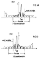
In Fig. 3 besitzt der Integralmonitorhohlleiter MH im Gegensatz zu der in Fig. 1 wiedergegebenen Anordnung zwei einander gegenüberliegende Ausgänge A1 und A2. Jedem Eingang ist eine Signalaufbereitungsschaltung SAB1, SAB2 nachgeschaltet, die ein aufbereitetes Monitorsignal über einen Analog/Digitalumsetzer AD1, AD2 einer Signalverarbeitungsschaltung SV zuführt. Die an den Ausgängen A1 und A2 zu entnehmenden Monitorsignale MS1, MS2 unterscheiden sich voneinander in ihrem Beobachtungswinkel θM. Unter den unterschiedlichen Beobachtungswinkeln sind bei eingeschränktem Schwenkbereich jeweils unterschiedliche Bereiche MS1, MS2 des dem Fernfelddiagramm entsprechenden Gesamt-Monitorsignals sichtbar. Die Breite dieser sichtbaren Bereiche entspricht jeweils dem Schwenkbereich der Antenne. Ihre Lage geht aus Fig. 4a und Fig. 4b hervor:In FIG. 3, the integral monitor waveguide MH, in contrast to the arrangement shown in FIG. 1, has two opposite outputs A1 and A2. A signal processing circuit SAB1, SAB2 is connected downstream of each input conditioned monitor signal via an analog / digital converter AD1, AD2 a signal processing circuit SV supplies. The monitor signals MS1, MS2 to be taken at the outputs A1 and A2 differ from one another in their observation angle θ M. With the limited swivel range, different areas MS1, MS2 of the overall monitor signal corresponding to the far field diagram are visible under the different observation angles. The width of these visible areas corresponds to the swivel range of the antenna. Their position can be seen from FIGS. 4a and 4b:
In Fig. 4a erscheint das dem Ausgang A1 entnommene Monitorsignal MS1 unter einem Beobachtungswinkel θM1 , von der Antennenmitte (Mittelsenkrechte auf der Antennengruppenachse) aus gesehen, somit nach rechts versetzt. Es bleiben damit auf der rechten Seite gelegene Teile des eine Periode breiten, zur Berechnung der Aperturbelegung notwendigen Gesamt-Monitorsignals unsichtbar. Die linke Signalseite ist dagegen bis zum Periodenbeginn sichtbar. Bei dem in Fig. 4b dargestellten, dem Ausgang A2 entnommenen Monitorsignal MS2 liegt der Beobachtungswinkel θM2 bezüglich der Antennenmitte spiegelbildlich zu dem des Monitorsignals MS1, d.h. von der Antennenmitte aus nach links versetzt. Der vom Monitorsignal erfaßte sichtbare Bereich umfaßt damit Anteile des Gesamt-Monitorsignals, die bis zur rechten Grenze der Signalperiode reichen, während am linken Rand der Signalperiode Signalanteile unsichtbar bleiben. Aus Fig. 4a und Fig. 4b ist erkennbar, daß die Monitorsignale MS1 und MS2 hier zusammen genommen die gesamte Information einer Periode des Monitorsignals enthalten. Die zur Berechnung der Aperturbelegung erforderlichen Abtastwerte können damit bei numerischer Berücksichtigung der unterschiedlichen Beobachtungswinkel aus den beiden Monitorsignalen gewonnen werden.4a, the monitor signal MS1 taken from the output A1 appears at an observation angle θ M1 , seen from the center of the antenna (perpendicular to the axis of the antenna group), thus offset to the right. Parts on the right-hand side of the total monitor signal that is one period wide and necessary for calculating the aperture assignment remain invisible. The left signal side is visible until the start of the period. In the case of the monitor signal MS2 shown in FIG. 4b and taken from the output A2, the observation angle θ M2 with respect to the center of the antenna is a mirror image of that of the monitor signal MS1, ie offset to the left from the center of the antenna. The visible area covered by the monitor signal thus comprises portions of the total monitor signal which extend to the right limit of the signal period, while signal portions remain invisible on the left edge of the signal period. It can be seen from FIGS. 4a and 4b that the monitor signals MS1 and MS2 taken together contain the entire information of one period of the monitor signal. The sampling values required for calculating the aperture assignment can thus be obtained from the two monitor signals when the different observation angles are taken into account numerically.
In besonderen Fällen, z.B. bei Elevationsantennen, die einen Schwenkbereich von nur 15° überstreichen, reicht selbst eine Verdoppelung des sichtbaren Bereichs des Gesamt-Monitorsignals durch Erfassung eines unter einem gespiegelten Beobachtungswinkel gewonnenen zusätzlichen Monitorsignals nicht aus, um das einer ganzen Periode des Antennenfernfeldes entsprechende Gesamt-Monitorsignal sichtbar zu machen.
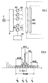
Um auch hier Information für eine ganze Periode des Monitorsignals zu erhalten, ist in einem in Fig. 5 dargestellten Ausführungsbeispiel ein zweiter Integralmonitorhohlleiter MH2 vorgesehen, dessen, an beiden Enden befindlichen Ausgängen ebenfalls Monitorsignale entnommen werden. Da der Beobachtungswinkel eines Integralmonitorhohlleiters durch das Design des Hohlleiters sowie durch die Lage und Gestalt der Koppelöffnungen beeinflußt und eingestellt werden kann, ist es durch derartige Einstellung möglich, noch nicht durch auswertbare Monitorsignale sichtbar gemachte Teile eines eine Periode breiten Gesamt-Monitorsignals durch Monitorsignale eines weiteren Integralmonitorhohlleiters sichtbar zu machen.
In Fig. 6 ist dargestellt, wie bei einer Antenne mit stark eingeschränktem Schwenkbereich eine ganze Periode eines Gesamt-Monitorsignals aus vier in ihrer Breite eingeschränkten Monitorsignalen MSI...MSIV mit den Beobachtungswinkeln θA , -θA , θB , -θB zusammengesetzt werden kann.In special cases, for example with elevation antennas that cover a swivel range of only 15 °, even one is sufficient Doubling the visible range of the overall monitor signal by detecting an additional monitor signal obtained at a mirrored viewing angle does not suffice in order to make the overall monitor signal corresponding to an entire period of the far antenna field visible.
In order to obtain information here for a whole period of the monitor signal, a second integral monitor waveguide MH2 is provided in an exemplary embodiment shown in FIG. 5, the outputs of which are located at both ends of the monitor signals are also taken. Since the observation angle of an integral monitor waveguide can be influenced and set by the design of the waveguide and by the position and shape of the coupling openings, it is possible by such setting to make parts of a period-wide total monitor signal that are not yet made visible by monitor signals by monitor signals from another To make integral monitor waveguide visible.
FIG. 6 shows how, in the case of an antenna with a severely restricted swiveling range, an entire period of an overall monitor signal comprising four monitor signals MSI ... MSIV with a limited width with the observation angles θ A , -θ A , θ B , -θ B can be put together.
Claims (3)
- Apparatus for determining the aperture illumination of a phased-array antenna having a plurality of radiating elements (SE1...SEn) respectively coupled via coupling apertures to an integral monitor waveguide (MH), said apparatus comprising a signal-conditioning circuit (SAB), connected to a first output (A) of the integral monitor waveguide, for determining a real part and an imaginary part, but at least the real part, of a time-dependent complex monitor signal provided by the integral monitor waveguide, said signal-conditioning circuit (SAB) feeding said real and imaginary parts, or only said real part, to a signal-processing circuit (SV) which continuously calculates, with the help of a signal processor, the aperture illumination of the array antenna from the monitor-signal parts determined by the signal-conditioning circuit,
characterized in
that the integral monitor waveguide (MH1, MH2) has at least one additional output (A2) which is spatially separated from the first output (A1), said additional output (A2) being connected to an additional signal-conditioning circuit (SAB2) which determines a real part and an imaginary part, or only the real part, of a time-dependent complex monitor signal provided at the additional output, and which feeds said real and imaginary parts, or only said real part, to the signal-processing circuit (SV), and that the signal processor of the signal-processing circuit uses the monitor-signal parts determined by the additional signal-processing circuit (SAB2) to calculate the aperture illumination of the array antenna. - Apparatus as claimed in claim 1, characterized in that two outputs (A1, A2) of the integral monitor waveguide (MH) are provided at opposite ends of this component.
- Apparatus as claimed in claim 1 or 2, characterized in that one or more additional integral monitor waveguides (MH2) are provided whose outputs provide monitor signals at monitor angles different from those at which monitor signals are provided at the outputs of the first integral monitor waveguide, that the outputs of said additional integral monitor waveguide(s) are coupled to additional signal-conditioning circuits which determine a real part and an imaginary part, or only the real part, of the monitor signals provided by the additional integral monitor waveguides, and feed said real and imaginary parts, or only said real part, to the signal processor, and that the signal processor uses the monitor-signal parts determined by the additional signal-conditioning circuits to calculate the aperture illumination.
Applications Claiming Priority (2)
| Application Number | Priority Date | Filing Date | Title |
|---|---|---|---|
| DE4227857 | 1992-08-22 | ||
| DE4227857A DE4227857A1 (en) | 1992-08-22 | 1992-08-22 | Device for obtaining the aperture assignment of a phase-controlled group antenna |
Publications (2)
| Publication Number | Publication Date |
|---|---|
| EP0584635A1 EP0584635A1 (en) | 1994-03-02 |
| EP0584635B1 true EP0584635B1 (en) | 1997-01-29 |
Family
ID=6466145
Family Applications (1)
| Application Number | Title | Priority Date | Filing Date |
|---|---|---|---|
| EP93112787A Expired - Lifetime EP0584635B1 (en) | 1992-08-22 | 1993-08-10 | Device for obtaining the aperture configuration of a phased array antenna |
Country Status (6)
| Country | Link |
|---|---|
| US (1) | US5337059A (en) |
| EP (1) | EP0584635B1 (en) |
| JP (1) | JP3383369B2 (en) |
| AU (1) | AU668192B2 (en) |
| CA (1) | CA2104261C (en) |
| DE (2) | DE4227857A1 (en) |
Cited By (1)
| Publication number | Priority date | Publication date | Assignee | Title |
|---|---|---|---|---|
| CN102792521A (en) * | 2010-03-18 | 2012-11-21 | 阿尔卡特朗讯 | Calibration of active antenna arrays for mobile telecommunications |
Families Citing this family (6)
| Publication number | Priority date | Publication date | Assignee | Title |
|---|---|---|---|---|
| DE19711655A1 (en) * | 1997-03-20 | 1998-09-24 | Alsthom Cge Alcatel | Integral monitor network for instrument landing system |
| US5841394A (en) * | 1997-06-11 | 1998-11-24 | Itt Manufacturing Enterprises, Inc. | Self calibrating radar system |
| DE19953271A1 (en) * | 1999-11-06 | 2001-05-10 | Airsys Navigation Systems Gmbh | Transmitting antenna |
| KR101012161B1 (en) * | 2010-08-25 | 2011-02-07 | 엘아이지넥스원 주식회사 | System and method for measuring antenna patterns of digital radar |
| US8686896B2 (en) * | 2011-02-11 | 2014-04-01 | Src, Inc. | Bench-top measurement method, apparatus and system for phased array radar apparatus calibration |
| CN113866522B (en) * | 2021-12-07 | 2022-02-22 | 成都锐芯盛通电子科技有限公司 | Directional diagram test method and system of phased array antenna |
Family Cites Families (6)
| Publication number | Priority date | Publication date | Assignee | Title |
|---|---|---|---|---|
| US4453164A (en) * | 1982-07-26 | 1984-06-05 | Rca Corporation | Method of determining excitation of individual elements of a phase array antenna from near-field data |
| US4536766A (en) * | 1982-09-07 | 1985-08-20 | Hazeltine Corporation | Scanning antenna with automatic beam stabilization |
| AU565039B2 (en) * | 1983-05-23 | 1987-09-03 | Hazeltine Corp. | Resonant waveguide aperture manifold |
| US4926186A (en) * | 1989-03-20 | 1990-05-15 | Allied-Signal Inc. | FFT-based aperture monitor for scanning phased arrays |
| DE4012101A1 (en) * | 1990-04-14 | 1991-10-17 | Standard Elektrik Lorenz Ag | Signal acquisition with phased controlled group antennae - using integral waveguide with Fourier transformation in conjunction with discrete Hilbert transformation |
| NO177475C (en) * | 1990-04-14 | 1995-09-20 | Sel Alcatel Ag | Method and apparatus by antenna |
-
1992
- 1992-08-22 DE DE4227857A patent/DE4227857A1/en not_active Withdrawn
-
1993
- 1993-08-10 EP EP93112787A patent/EP0584635B1/en not_active Expired - Lifetime
- 1993-08-10 DE DE59305316T patent/DE59305316D1/en not_active Expired - Lifetime
- 1993-08-13 AU AU44634/93A patent/AU668192B2/en not_active Ceased
- 1993-08-17 CA CA002104261A patent/CA2104261C/en not_active Expired - Fee Related
- 1993-08-23 US US08/110,364 patent/US5337059A/en not_active Expired - Lifetime
- 1993-08-23 JP JP20803093A patent/JP3383369B2/en not_active Expired - Fee Related
Cited By (2)
| Publication number | Priority date | Publication date | Assignee | Title |
|---|---|---|---|---|
| CN102792521A (en) * | 2010-03-18 | 2012-11-21 | 阿尔卡特朗讯 | Calibration of active antenna arrays for mobile telecommunications |
| CN102792521B (en) * | 2010-03-18 | 2015-07-15 | 阿尔卡特朗讯 | Calibration of active antenna arrays for mobile telecommunications |
Also Published As
| Publication number | Publication date |
|---|---|
| JPH06196923A (en) | 1994-07-15 |
| CA2104261A1 (en) | 1994-02-23 |
| DE4227857A1 (en) | 1994-02-24 |
| US5337059A (en) | 1994-08-09 |
| EP0584635A1 (en) | 1994-03-02 |
| AU668192B2 (en) | 1996-04-26 |
| AU4463493A (en) | 1994-02-24 |
| DE59305316D1 (en) | 1997-03-13 |
| CA2104261C (en) | 2001-12-18 |
| JP3383369B2 (en) | 2003-03-04 |
Similar Documents
| Publication | Publication Date | Title |
|---|---|---|
| DE3743123C2 (en) | Antenna device | |
| DE2248325C2 (en) | Antenna for sending or receiving with swiveling beam | |
| DE112014006707B4 (en) | ARRAY ANTENNA DEVICE | |
| DE102011088045B4 (en) | Phased array antenna and phase calibration method | |
| EP2965382B1 (en) | Antenna arrangement with variable direction characteristic | |
| EP1530816B9 (en) | Calibration device for a switchable antenna array and corresponding operating method | |
| DE102010040749A1 (en) | Radar device for emitting and receiving electrical waves with grating lobes | |
| DE3042456A1 (en) | ANTENNA WITH A DEVICE FOR ROTATING THE POLARIZATION LEVEL | |
| EP0584635B1 (en) | Device for obtaining the aperture configuration of a phased array antenna | |
| DE69827493T2 (en) | SELF-CALIBRATING RADAR SYSTEM | |
| DE2203442B1 (en) | Radio navigation system with cyclical pulse radiation through a line of emitters for determining azimuth or elevation | |
| DE19627218B4 (en) | radar device | |
| EP0935825B1 (en) | Radar sensor for a vehicle | |
| DE2159140C3 (en) | Photoelectric detection system | |
| DE19927395A1 (en) | Device and method for increasing the angular resolution of an antenna arrangement | |
| EP0023606B1 (en) | Antenna system for locating the position of a microwave signal source | |
| DE3827589C2 (en) | ||
| EP0249753B1 (en) | Scanning-beam microwave landing system | |
| DE2505697C1 (en) | Interference protection method for an antenna with electronic beam swiveling and antenna for applying the method | |
| EP0501224B1 (en) | Waveguide slot antenna | |
| DE3440666C2 (en) | Anti-interference method and device for radar systems and radar system equipped with such a device | |
| DE2039325C3 (en) | Device for the automatic correction of frequency-dependent arrow errors as a result of influencing the antenna system in two-channel direction finders | |
| DE3006528A1 (en) | MULTI-BEAM ANTENNA AND METHOD FOR GENERATING AT LEAST ONE ZERO IN AN ANTENNA RADIATION DIAGRAM WITH WIDE RADIATION | |
| DE722438C (en) | Arrangement for automatic target acquisition by aircraft | |
| DE2737750C1 (en) | Aircraft antenna system for IFF boarding |
Legal Events
| Date | Code | Title | Description |
|---|---|---|---|
| PUAI | Public reference made under article 153(3) epc to a published international application that has entered the european phase |
Free format text: ORIGINAL CODE: 0009012 |
|
| AK | Designated contracting states |
Kind code of ref document: A1 Designated state(s): DE FR GB IT |
|
| 17P | Request for examination filed |
Effective date: 19940414 |
|
| GRAG | Despatch of communication of intention to grant |
Free format text: ORIGINAL CODE: EPIDOS AGRA |
|
| 17Q | First examination report despatched |
Effective date: 19960313 |
|
| GRAH | Despatch of communication of intention to grant a patent |
Free format text: ORIGINAL CODE: EPIDOS IGRA |
|
| GRAH | Despatch of communication of intention to grant a patent |
Free format text: ORIGINAL CODE: EPIDOS IGRA |
|
| GRAA | (expected) grant |
Free format text: ORIGINAL CODE: 0009210 |
|
| AK | Designated contracting states |
Kind code of ref document: B1 Designated state(s): DE FR GB IT |
|
| REF | Corresponds to: |
Ref document number: 59305316 Country of ref document: DE Date of ref document: 19970313 |
|
| GBT | Gb: translation of ep patent filed (gb section 77(6)(a)/1977) |
Effective date: 19970321 |
|
| ITF | It: translation for a ep patent filed |
Owner name: 0508;E1MIFBORSANO CORRADO |
|
| ET | Fr: translation filed | ||
| PLBE | No opposition filed within time limit |
Free format text: ORIGINAL CODE: 0009261 |
|
| STAA | Information on the status of an ep patent application or granted ep patent |
Free format text: STATUS: NO OPPOSITION FILED WITHIN TIME LIMIT |
|
| 26N | No opposition filed | ||
| REG | Reference to a national code |
Ref country code: GB Ref legal event code: IF02 |
|
| PGFP | Annual fee paid to national office [announced via postgrant information from national office to epo] |
Ref country code: IT Payment date: 20100817 Year of fee payment: 18 Ref country code: FR Payment date: 20100824 Year of fee payment: 18 Ref country code: DE Payment date: 20100812 Year of fee payment: 18 |
|
| PGFP | Annual fee paid to national office [announced via postgrant information from national office to epo] |
Ref country code: GB Payment date: 20100811 Year of fee payment: 18 |
|
| GBPC | Gb: european patent ceased through non-payment of renewal fee |
Effective date: 20110810 |
|
| REG | Reference to a national code |
Ref country code: FR Ref legal event code: ST Effective date: 20120430 |
|
| PG25 | Lapsed in a contracting state [announced via postgrant information from national office to epo] |
Ref country code: IT Free format text: LAPSE BECAUSE OF NON-PAYMENT OF DUE FEES Effective date: 20110810 |
|
| REG | Reference to a national code |
Ref country code: DE Ref legal event code: R119 Ref document number: 59305316 Country of ref document: DE Effective date: 20120301 |
|
| PG25 | Lapsed in a contracting state [announced via postgrant information from national office to epo] |
Ref country code: GB Free format text: LAPSE BECAUSE OF NON-PAYMENT OF DUE FEES Effective date: 20110810 Ref country code: FR Free format text: LAPSE BECAUSE OF NON-PAYMENT OF DUE FEES Effective date: 20110831 |
|
| PG25 | Lapsed in a contracting state [announced via postgrant information from national office to epo] |
Ref country code: DE Free format text: LAPSE BECAUSE OF NON-PAYMENT OF DUE FEES Effective date: 20120301 |