EP0582139A1 - Machine à découper en tranches, notamment pour des balles de tabac - Google Patents
Machine à découper en tranches, notamment pour des balles de tabac Download PDFInfo
- Publication number
- EP0582139A1 EP0582139A1 EP93111734A EP93111734A EP0582139A1 EP 0582139 A1 EP0582139 A1 EP 0582139A1 EP 93111734 A EP93111734 A EP 93111734A EP 93111734 A EP93111734 A EP 93111734A EP 0582139 A1 EP0582139 A1 EP 0582139A1
- Authority
- EP
- European Patent Office
- Prior art keywords
- slicing machine
- outlet portal
- bale
- conveyor
- carriage
- Prior art date
- Legal status (The legal status is an assumption and is not a legal conclusion. Google has not performed a legal analysis and makes no representation as to the accuracy of the status listed.)
- Granted
Links
Images


Classifications
-
- A—HUMAN NECESSITIES
- A24—TOBACCO; CIGARS; CIGARETTES; SIMULATED SMOKING DEVICES; SMOKERS' REQUISITES
- A24B—MANUFACTURE OR PREPARATION OF TOBACCO FOR SMOKING OR CHEWING; TOBACCO; SNUFF
- A24B3/00—Preparing tobacco in the factory
- A24B3/06—Loosening tobacco leaves or cut tobacco
-
- Y—GENERAL TAGGING OF NEW TECHNOLOGICAL DEVELOPMENTS; GENERAL TAGGING OF CROSS-SECTIONAL TECHNOLOGIES SPANNING OVER SEVERAL SECTIONS OF THE IPC; TECHNICAL SUBJECTS COVERED BY FORMER USPC CROSS-REFERENCE ART COLLECTIONS [XRACs] AND DIGESTS
- Y10—TECHNICAL SUBJECTS COVERED BY FORMER USPC
- Y10S—TECHNICAL SUBJECTS COVERED BY FORMER USPC CROSS-REFERENCE ART COLLECTIONS [XRACs] AND DIGESTS
- Y10S83/00—Cutting
- Y10S83/929—Particular nature of work or product
- Y10S83/931—Tobacco
-
- Y—GENERAL TAGGING OF NEW TECHNOLOGICAL DEVELOPMENTS; GENERAL TAGGING OF CROSS-SECTIONAL TECHNOLOGIES SPANNING OVER SEVERAL SECTIONS OF THE IPC; TECHNICAL SUBJECTS COVERED BY FORMER USPC CROSS-REFERENCE ART COLLECTIONS [XRACs] AND DIGESTS
- Y10—TECHNICAL SUBJECTS COVERED BY FORMER USPC
- Y10T—TECHNICAL SUBJECTS COVERED BY FORMER US CLASSIFICATION
- Y10T83/00—Cutting
- Y10T83/343—With means to deform work temporarily
-
- Y—GENERAL TAGGING OF NEW TECHNOLOGICAL DEVELOPMENTS; GENERAL TAGGING OF CROSS-SECTIONAL TECHNOLOGIES SPANNING OVER SEVERAL SECTIONS OF THE IPC; TECHNICAL SUBJECTS COVERED BY FORMER USPC CROSS-REFERENCE ART COLLECTIONS [XRACs] AND DIGESTS
- Y10—TECHNICAL SUBJECTS COVERED BY FORMER USPC
- Y10T—TECHNICAL SUBJECTS COVERED BY FORMER US CLASSIFICATION
- Y10T83/00—Cutting
- Y10T83/444—Tool engages work during dwell of intermittent workfeed
- Y10T83/463—Work-feed element contacts and moves with work
- Y10T83/4635—Comprises element entering aperture in, or engaging abutment surface on, work
-
- Y—GENERAL TAGGING OF NEW TECHNOLOGICAL DEVELOPMENTS; GENERAL TAGGING OF CROSS-SECTIONAL TECHNOLOGIES SPANNING OVER SEVERAL SECTIONS OF THE IPC; TECHNICAL SUBJECTS COVERED BY FORMER USPC CROSS-REFERENCE ART COLLECTIONS [XRACs] AND DIGESTS
- Y10—TECHNICAL SUBJECTS COVERED BY FORMER USPC
- Y10T—TECHNICAL SUBJECTS COVERED BY FORMER US CLASSIFICATION
- Y10T83/00—Cutting
- Y10T83/647—With means to convey work relative to tool station
- Y10T83/6656—Rectilinear movement only
- Y10T83/6657—Tool opposing pusher
- Y10T83/6664—Lever, cam, or link actuated
-
- Y—GENERAL TAGGING OF NEW TECHNOLOGICAL DEVELOPMENTS; GENERAL TAGGING OF CROSS-SECTIONAL TECHNOLOGIES SPANNING OVER SEVERAL SECTIONS OF THE IPC; TECHNICAL SUBJECTS COVERED BY FORMER USPC CROSS-REFERENCE ART COLLECTIONS [XRACs] AND DIGESTS
- Y10—TECHNICAL SUBJECTS COVERED BY FORMER USPC
- Y10T—TECHNICAL SUBJECTS COVERED BY FORMER US CLASSIFICATION
- Y10T83/00—Cutting
- Y10T83/748—With work immobilizer
- Y10T83/7593—Work-stop abutment
- Y10T83/764—Retractable
-
- Y—GENERAL TAGGING OF NEW TECHNOLOGICAL DEVELOPMENTS; GENERAL TAGGING OF CROSS-SECTIONAL TECHNOLOGIES SPANNING OVER SEVERAL SECTIONS OF THE IPC; TECHNICAL SUBJECTS COVERED BY FORMER USPC CROSS-REFERENCE ART COLLECTIONS [XRACs] AND DIGESTS
- Y10—TECHNICAL SUBJECTS COVERED BY FORMER USPC
- Y10T—TECHNICAL SUBJECTS COVERED BY FORMER US CLASSIFICATION
- Y10T83/00—Cutting
- Y10T83/95—Machine frame
- Y10T83/96—Guard
Definitions
- the present invention relates to a slicing machine, particularly for bales of tobacco.
- the slicing machine is characterized in that it comprises: a support structure with an inlet opening for the insertion of a bale, and with an outlet portal, a conveyor for transferring a bale from said inlet opening to the outlet portal, a guillotine-like cutting device associated with said outlet portal and comprising a cutting blade which is movable between a raised position in which it allows a bale carried by the conveyor to advance through the portal, and a lowered, cutting position, a thrust device movable in said structure, above the conveyor, and comprising a thrust member which can bear on the rear end surface of the bale carried by the conveyor in order to urge it towards the outlet portal in a controlled manner, and an abutment device associated with the outlet portal, downstream of the cutting device, and comprising a movable stop member which can assume a working position in which it defines a position where the bale advancing through the outlet portal in use is stopped at a predetermined distance from the path of the cutting blade, the distance corresponding to the desired thickness
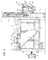
- a slicing machine according to the invention comprises a substantially tunnel-shaped support structure 1 with an inlet opening 2 (Figure 2) and an outlet portal 3.
- At least one side wall of the tunnel-shaped support structure 1 has a plurality of holes or windows 4 with which respective transparent closure doors 5, for example, glazed doors, are associated.
- the outlet portal 3 is defined by a pair of hollow vertical uprights 6 surmounted by a cross member 7.
- the uprights 6 of the outlet portal 3 are somewhat taller than the top of the tunnel-shaped support structure 1.
- a belt conveyor In the bottom of said tunnel-shaped structure there is a belt conveyor, generally indicated 9 in Figure 2.
- This conveyor comprises an endless belt or piece of fabric 10 which is stretched between rollers 11 to 16 and is moved by an electric motor 17 fixed to the support structure 1.
- the activation of the motor moves the fabric or belt 10 so that its upper pass moves from the inlet opening of the support structure 2 towards the outlet portal 3, as indicated by the arrow F1 in Figure 2.
- a carriage 18 is movable in the tunnel-shaped structure 1 above the belt conveyor 9 and, in the embodiment shown ( Figure 2), comprises two lateral arms 18a joined together by a cross member 18b.
- This carriage is movable within the support structure 1 between the inlet opening 2 and the portal 3, parallel to the conveyor belt 9, by the operation of a drive system which comprises an electric motor 19 and associated transmission chains 20 extending between sprockets 21.
- Respective drive cylinders 22 are connected to the lateral arms 18a of the carriage 18.
- the rod of each cylinder is articulated to a first end 23a of an arm 23 which can pivot relative to the carriage in a vertical plane parallel to the direction of movement of said carriage, about a pin 24.
- a thrust member 25a is articulated between the other ends 23b of the arms 23 and extends transverse the direction of movement of the carriage 18.
- the thrust member is essentially prismatic in shape and has a flat thrust surface,indicated 25a in Figures 2 to 4.
- a further electric motor carried by a lateral arm 18a of the carriage 18 is indicated 26 in Figure 2 and, by means of a transmission chain 27 ( Figures 2 and 4), can rotate a sprocket 28 which is fixed to the thrust member 25 and is coaxial with the axis of articulation of the latter to the ends 23b of the pivoting arms 23.
- the portions 23b of the pivoting arms 23 extend parallel to and adjacent the lateral arms 18a of the carriage 18 and the thrust member 25 extends above the plane of the carriage with its thrust surface 25a facing upwardly.
- the portions 23b of the pivoting arms 23 extend downwardly beneath the general plane of the carriage 18 towards the conveyor belt 10 and the thrust member 25 extends a short distance from the conveyor belt 10 and is oriented with its thrust surface 25a parallel to and facing the outlet portal 3.
- the thrust member 25 can be moved from the position of Figure 3 to the position of Figure 4 by the pivoting of the arms 23 (by means of the cylinders 22) in combination with a simultaneous pivoting of the thrust member 25 about its axis of articulation to said arms (brought about by the operation of the electric motor 26).
- Two strong drive cylinders are fixed in the upper portions of the uprights 6 of the outlet portal 3.
- a guillotine-like cutting device generally indicated 40 in Figure 2.
- This device comprises a plate 41 the bottom of which is connected to a cutting blade 42.
- the vertical sides of the plate 41 are connected to two arms 43, the lower ends of which are connected to the rods of the cylinders 30.
- the plate 41 and the associated cutting blade 42 can be moved by means of the cylinders 30 between the raised position shown in Figures 2 to 5 and a lowered, cutting position (not shown).
- a compressor device associated with the unit formed by the plate 41 and the cutting blade 42 is generally indicated 70 in Figures 2, 5, 6 and 7.
- This device comprises a horizontal transverse pressure member 71, the ends of which are connected to the lower portions of two vertical arms 72, the outer sides of the top portions of which carry guide rollers 73 ( Figures 5 to 7) which can run in vertical guides 74 ( Figures 6 and 7) carried by the uprights 6 of the portal 3.
- the upper ends of the arms 72 have respective bent tabs 72a ( Figures 2, 6 and 7) for bearing on the upper edge of the plate 41.
- the compressor device 70 is disposed immediately upstream of the plate 41 and the associated blade 42 and can move vertically, together with said plate 41, as a result of the operation of the cylinders 30.
- This device is not fixed to said plate, however, so that it can, in fact, be entrained upwardly by this plate when the plate is raised by the cylinders 30 and fall by gravity when said plate is lowered, until it bears on and compresses an underlying bale of tobacco B extending through the portal 3 whilst the plate 41 and the blade 42, which are entrained further downwards by the cylinders 30, penetrate the bale (Figure 7).
- An abutment device connected to the outlet portal 3 downstream of the guillotine-like cutting device 40 is generally indicated 50 in the drawings.
- This abutment device comprises a substantially tank-like casing 51 disposed with its opening facing inwardly of the tunnel-shaped support structure 1.
- a stop member 52 movable in the casing 51, has a front wall 52a which is oriented vertically and faces inwardly of the tunnel-shaped structure 1.
- This stop member is movable away from and towards the guillotine-like cutting device in the directions indicated by the arrows F3 in Figures 2 and 4, along guide rails 54 ( Figures 3 and 4) in the casing 51.
- the stop member 52 can be moved by means of a drive cylinder 55 the top of which is articulated to the casing 51 and the rod of which is articulated to an operating arm 56 of a kinematic mechanism connected to the member 52.
- This kinematic mechanism comprises a shaft 57 ( Figure 2) which can rotate in the casing 51 and to which the arm 56, as well as two further arms or cranks 58 connected to the member 52 by means of respective articulated connecting rods 59, are fixed torsionally.
- the slicing machine described above operates in the following manner.
- a bale of tobacco is introduced into the tunnel-shaped structure 1 through its inlet opening 2 as indicated in Figure 3.
- This bale may be introduced manually or may be supplied to the slicing machine, for example, by means of conveyor devices, not shown.
- the machine assumes the configuration shown in Figure 3, in which the thrust member 25 is in the raised position and does not obstruct the transfer of the bale B towards the outlet portal 3 by the conveyor belt 10.
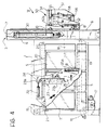
- the plate 41 and the associated cutting blade 42 are in the raised position, so that the bale B is carried through the portal 3 by the belt 10 until it stops against the stop surface 52a of the abutment device 50 as shown in Figure 4.
- the blade 42 and the associated plate 41 are then returned to the raised position by means of the cylinders 30. This plate entrains the compressor device 70 and raises it again.
- the coordinated operation of the electric motor 19 and the drive cylinder 55 then moves the thrust member 25 towards the portal 3 and retracts the stop member 52 within the casing 51 until the slice previously cut is free to fall downwards by gravity where conveyor devices may be provided for collecting it and moving it away from the slicing machine.
- the stop member 52 of the abutment device 50 is then advanced towards the portal 3 again until it reaches its working position at a distance D from the path of the cutting blade 42, this distance corresponding to the thickness of the slices into which the bale B is to be divided.
- the bale B is brought against the surface 52a of the stop member 52 again as a result of a further movement of the thrust member 25 towards the outlet portal 3.
- the cutting blade 42 is then lowered again in order to cut another slice.
- the operation proceeds in the manner described above until the tobacco bale B has been used up, after which the slicing machine is returned to its initial configuration and the operation recommences with the supply of a further bale of tobacco through its inlet portal 2.
- the support casing 51 of the abutment device 50 is connected to one of the uprights 6 of the portal 3 by means of hinges 60 ( Figure 1) which enable it to pivot in a horizontal plane after the release of locking means 61 which connect it releasably to the other upright of the portal.
- the coordinated operation of the various electric motors and of the various operating cylinders of the machine may be achieved in known manner by means of a control unit, not shown.
Landscapes
- Manufacturing Of Cigar And Cigarette Tobacco (AREA)
- Manufacture Of Tobacco Products (AREA)
- Preliminary Treatment Of Fibers (AREA)
- Pretreatment Of Seeds And Plants (AREA)
Applications Claiming Priority (2)
| Application Number | Priority Date | Filing Date | Title |
|---|---|---|---|
| ITTO920671A IT1256913B (it) | 1992-08-03 | 1992-08-03 | Macchina affettatrice, particolarmente per balle di tabacco. |
| ITTO920671 | 1992-08-03 |
Publications (2)
| Publication Number | Publication Date |
|---|---|
| EP0582139A1 true EP0582139A1 (fr) | 1994-02-09 |
| EP0582139B1 EP0582139B1 (fr) | 1998-09-02 |
Family
ID=11410664
Family Applications (1)
| Application Number | Title | Priority Date | Filing Date |
|---|---|---|---|
| EP93111734A Expired - Lifetime EP0582139B1 (fr) | 1992-08-03 | 1993-07-22 | Machine à découper en tranches, notamment pour des balles de tabac |
Country Status (9)
| Country | Link |
|---|---|
| US (1) | US5435218A (fr) |
| EP (1) | EP0582139B1 (fr) |
| JP (1) | JPH06165664A (fr) |
| AT (1) | ATE170367T1 (fr) |
| AU (1) | AU656684B2 (fr) |
| DE (1) | DE69320736T2 (fr) |
| DK (1) | DK0582139T3 (fr) |
| ES (1) | ES2123020T3 (fr) |
| IT (1) | IT1256913B (fr) |
Cited By (9)
| Publication number | Priority date | Publication date | Assignee | Title |
|---|---|---|---|---|
| EP0699395A2 (fr) | 1994-08-25 | 1996-03-06 | Hauni Maschinenbau Aktiengesellschaft | Dispositif pour la coupe en tranches de ballots |
| EP1502511A2 (fr) * | 2003-07-28 | 2005-02-02 | Hauni Maschinenbau AG | Delamination de balles de tabac |
| CN104273645A (zh) * | 2013-07-09 | 2015-01-14 | 豪尼机械制造股份公司 | 构造并且设立用于自动地从由烟草加工业的材料构成的料包上分割切片的装置 |
| CN105014715A (zh) * | 2014-04-13 | 2015-11-04 | 胡刘满 | 一种快速切片茯苓机 |
| CN106108101A (zh) * | 2016-08-26 | 2016-11-16 | 红塔烟草(集团)有限责任公司 | 一种可调式烟叶分切刀机装置 |
| CN106614874A (zh) * | 2017-01-27 | 2017-05-10 | 成都蒲江珂贤科技有限公司 | 一种用于辣条切割和撒料的装置 |
| CN109452683A (zh) * | 2018-12-06 | 2019-03-12 | 阜阳市卓创科技服务生产力促进中心 | 一种烟用原材料加工用切制设备及其切制方法 |
| CN113146706A (zh) * | 2021-04-08 | 2021-07-23 | 刘英海 | 一种无触碰式口罩回收销毁装置 |
| WO2023191744A1 (fr) * | 2022-03-31 | 2023-10-05 | Adeba Mühendi̇sli̇k Danişmanlik Halkla İli̇şki̇ler İnşaat Sanayi̇ Ve Ti̇caret Anoni̇m Şi̇rketi̇ | Système à fonctionnalité robotique pour un processus de division d'un ballot de tabac comprimé et emballé à l'intérieur de son boîtier d'origine en 2 morceaux ou plus |
Families Citing this family (16)
| Publication number | Priority date | Publication date | Assignee | Title |
|---|---|---|---|---|
| US5938580A (en) * | 1994-04-15 | 1999-08-17 | Ranpak Corp. | Cushioning conversion machine with restricted access to a cutting assembly |
| US5542325A (en) * | 1994-08-30 | 1996-08-06 | Bane, Iii; Wiliam W. | Sheet cutting apparatus |
| US5598757A (en) * | 1995-02-02 | 1997-02-04 | Lucent Technologies Inc. | Method for shearing panels |
| CA2259266A1 (fr) | 1996-06-28 | 1998-01-08 | Ranpak Corp. | Machine a transformer des materiaux de rembourrage |
| US6418826B1 (en) * | 1996-07-11 | 2002-07-16 | Japan Tobacco Inc. | Apparatus for slicing compression molded product of sheet-shaped material and split knife |
| US6053084A (en) * | 1998-11-13 | 2000-04-25 | Lucent Technologies, Inc. | System and method for cutting panels |
| US20050268765A1 (en) * | 2004-06-04 | 2005-12-08 | Chun-Jen Chien | Reciprocal bi-directional table saw |
| KR100785817B1 (ko) | 2007-01-17 | 2007-12-13 | (유)대도 | 가축사료 절단기 |
| CN102907754A (zh) * | 2011-08-03 | 2013-02-06 | 湖北中烟工业有限责任公司 | 一种立式剥料机 |
| CN103478880B (zh) * | 2013-10-11 | 2015-12-23 | 龙岩烟草工业有限责任公司 | 烟片挤压松散装置及其工艺 |
| CN103783655A (zh) * | 2014-02-25 | 2014-05-14 | 湖南省烟草公司永州市公司 | 一种铡刀式夹烟切柄操作台 |
| CN105108789B (zh) * | 2014-04-13 | 2017-03-01 | 孙建萍 | 一种对球菌类药材进行切片的设备 |
| CN104400808B (zh) * | 2014-10-23 | 2016-08-24 | 湖南皇爷食品有限公司 | 一种槟榔切片机 |
| CN104824819B (zh) * | 2015-04-01 | 2017-01-25 | 安徽中烟机械有限公司 | 烟包整包投料烟叶烟柄切断分离预松散设备 |
| CN106418657B (zh) * | 2016-09-26 | 2017-08-25 | 湖北中烟工业有限责任公司 | 一种分切、稳定片烟烟包的装置 |
| CN111329101B (zh) * | 2019-12-18 | 2022-04-19 | 湖北中烟工业有限责任公司 | 一种基于机器视觉检测技术的切片机精确控制系统 |
Citations (5)
| Publication number | Priority date | Publication date | Assignee | Title |
|---|---|---|---|---|
| DE1139419B (de) * | 1960-09-20 | 1962-11-08 | Reemtsma H F & Ph | Vorrichtung zum Abtrennen von Scheiben von einem Tabakballen |
| EP0159836A1 (fr) * | 1984-04-02 | 1985-10-30 | W.H. Dickinson Engineering Limited | Conditionnement de balles de tabac découpée en tranches |
| WO1987002868A1 (fr) * | 1985-11-13 | 1987-05-21 | Gbe International Plc | Machine a trancher des blocs de tabac |
| GB2246279A (en) * | 1990-07-28 | 1992-01-29 | Koerber Ag | Method of and apparatus for breaking up bales of condensed tobacco |
| EP0511196A1 (fr) * | 1991-04-26 | 1992-10-28 | SCHIFF & STERN KG | Dispositif pour le transport et la séparation de tranches des balles de tabac |
Family Cites Families (4)
| Publication number | Priority date | Publication date | Assignee | Title |
|---|---|---|---|---|
| US2207754A (en) * | 1938-12-31 | 1940-07-16 | Edward J Neary | Apparatus for slicing meats and other food products |
| US3180195A (en) * | 1960-10-10 | 1965-04-27 | Clark Julius | Apparatus for removing thermoplastic material from containers |
| JPS5929226B2 (ja) * | 1981-11-11 | 1984-07-19 | 日本たばこ産業株式会社 | 分割供給装置 |
| US5152208A (en) * | 1989-12-29 | 1992-10-06 | K. S. Macey Machine Company, Inc. | Book feeding and trimming apparatus |
-
1992
- 1992-08-03 IT ITTO920671A patent/IT1256913B/it active IP Right Grant
-
1993
- 1993-07-22 EP EP93111734A patent/EP0582139B1/fr not_active Expired - Lifetime
- 1993-07-22 DE DE69320736T patent/DE69320736T2/de not_active Expired - Lifetime
- 1993-07-22 ES ES93111734T patent/ES2123020T3/es not_active Expired - Lifetime
- 1993-07-22 DK DK93111734T patent/DK0582139T3/da active
- 1993-07-22 AT AT93111734T patent/ATE170367T1/de active
- 1993-07-26 US US08/097,779 patent/US5435218A/en not_active Expired - Lifetime
- 1993-07-28 AU AU44230/93A patent/AU656684B2/en not_active Ceased
- 1993-07-30 JP JP5208225A patent/JPH06165664A/ja active Pending
Patent Citations (5)
| Publication number | Priority date | Publication date | Assignee | Title |
|---|---|---|---|---|
| DE1139419B (de) * | 1960-09-20 | 1962-11-08 | Reemtsma H F & Ph | Vorrichtung zum Abtrennen von Scheiben von einem Tabakballen |
| EP0159836A1 (fr) * | 1984-04-02 | 1985-10-30 | W.H. Dickinson Engineering Limited | Conditionnement de balles de tabac découpée en tranches |
| WO1987002868A1 (fr) * | 1985-11-13 | 1987-05-21 | Gbe International Plc | Machine a trancher des blocs de tabac |
| GB2246279A (en) * | 1990-07-28 | 1992-01-29 | Koerber Ag | Method of and apparatus for breaking up bales of condensed tobacco |
| EP0511196A1 (fr) * | 1991-04-26 | 1992-10-28 | SCHIFF & STERN KG | Dispositif pour le transport et la séparation de tranches des balles de tabac |
Cited By (16)
| Publication number | Priority date | Publication date | Assignee | Title |
|---|---|---|---|---|
| EP0699395A2 (fr) | 1994-08-25 | 1996-03-06 | Hauni Maschinenbau Aktiengesellschaft | Dispositif pour la coupe en tranches de ballots |
| EP0699395A3 (fr) * | 1994-08-25 | 1999-01-27 | Hauni Maschinenbau Aktiengesellschaft | Dispositif pour la coupe en tranches de ballots |
| EP1502511A2 (fr) * | 2003-07-28 | 2005-02-02 | Hauni Maschinenbau AG | Delamination de balles de tabac |
| EP1502511A3 (fr) * | 2003-07-28 | 2005-04-13 | Hauni Maschinenbau AG | Delamination de balles de tabac |
| CN104273645B (zh) * | 2013-07-09 | 2018-07-20 | 虹霓机械制造有限公司 | 构造并且设立用于自动地从由烟草加工业的材料构成的料包上分割切片的装置 |
| DE102013107248A1 (de) | 2013-07-09 | 2015-01-15 | Hauni Maschinenbau Ag | Vorrichtung, ausgebildet und eingerichtet zum automatischen Trennen von Scheiben von einem aus Material der Tabak verarbeitenden Industrie bestehenden Ballen |
| EP2848132A1 (fr) | 2013-07-09 | 2015-03-18 | Hauni Maschinenbau AG | Dispositif, conçu et destiné à la séparation automatique de disque de balles composées de matériau provenant de l'industrie de traitement du tabac |
| DE102013107248B4 (de) * | 2013-07-09 | 2016-05-25 | Hauni Maschinenbau Ag | Vorrichtung, ausgebildet und eingerichtet zum automatischen Trennen von Scheiben von einem aus Material der Tabak verarbeitenden Industrie bestehenden Ballen |
| CN104273645A (zh) * | 2013-07-09 | 2015-01-14 | 豪尼机械制造股份公司 | 构造并且设立用于自动地从由烟草加工业的材料构成的料包上分割切片的装置 |
| CN105014715A (zh) * | 2014-04-13 | 2015-11-04 | 胡刘满 | 一种快速切片茯苓机 |
| CN105014714A (zh) * | 2014-04-13 | 2015-11-04 | 胡刘满 | 用于快速切片的新型机械设备 |
| CN106108101A (zh) * | 2016-08-26 | 2016-11-16 | 红塔烟草(集团)有限责任公司 | 一种可调式烟叶分切刀机装置 |
| CN106614874A (zh) * | 2017-01-27 | 2017-05-10 | 成都蒲江珂贤科技有限公司 | 一种用于辣条切割和撒料的装置 |
| CN109452683A (zh) * | 2018-12-06 | 2019-03-12 | 阜阳市卓创科技服务生产力促进中心 | 一种烟用原材料加工用切制设备及其切制方法 |
| CN113146706A (zh) * | 2021-04-08 | 2021-07-23 | 刘英海 | 一种无触碰式口罩回收销毁装置 |
| WO2023191744A1 (fr) * | 2022-03-31 | 2023-10-05 | Adeba Mühendi̇sli̇k Danişmanlik Halkla İli̇şki̇ler İnşaat Sanayi̇ Ve Ti̇caret Anoni̇m Şi̇rketi̇ | Système à fonctionnalité robotique pour un processus de division d'un ballot de tabac comprimé et emballé à l'intérieur de son boîtier d'origine en 2 morceaux ou plus |
Also Published As
| Publication number | Publication date |
|---|---|
| DK0582139T3 (da) | 1999-05-31 |
| JPH06165664A (ja) | 1994-06-14 |
| AU4423093A (en) | 1994-02-10 |
| US5435218A (en) | 1995-07-25 |
| IT1256913B (it) | 1995-12-27 |
| AU656684B2 (en) | 1995-02-09 |
| DE69320736T2 (de) | 1999-05-06 |
| ITTO920671A0 (it) | 1992-08-03 |
| EP0582139B1 (fr) | 1998-09-02 |
| ITTO920671A1 (it) | 1994-02-03 |
| DE69320736D1 (de) | 1998-10-08 |
| ATE170367T1 (de) | 1998-09-15 |
| ES2123020T3 (es) | 1999-01-01 |
Similar Documents
| Publication | Publication Date | Title |
|---|---|---|
| US5435218A (en) | Slicing machine | |
| AT390433B (de) | Vorrichtung zum aufbringen von flexiblen abstandhaltern | |
| US4444077A (en) | Flying saw apparatus | |
| JPH04500635A (ja) | 積重ねたシート状材料を切断する装置 | |
| EP1260327B1 (fr) | Machine à débiter en tranches équipée d'un dispositif de coupe de film ou de papier | |
| KR100769565B1 (ko) | 냉장육 고속 슬라이서 | |
| GB2118881A (en) | Method and apparatus for cutting continuous corrugated member | |
| CN109203116A (zh) | 一体化木材加工系统 | |
| CA2514864C (fr) | Trancheuse a pain | |
| US2824610A (en) | Mat segregating mechanism and methods | |
| DE68918819T2 (de) | Pressbiegen unter Verwendung eines Fördergurtes. | |
| DE2841386C2 (de) | Vorrichtung zum automatischen Querschneiden eines biegsamen Bahnmaterials | |
| DE2430043A1 (de) | Verfahren zum beschneiden von papierstapeln | |
| CN109548538A (zh) | 苹果快速套袋系统及方法 | |
| CN113977660A (zh) | 一种用于复合板生产用切断装置 | |
| DE602004004946T2 (de) | Riemenantriebsanordnung für eine behälterprüfmaschine | |
| JP3213084B2 (ja) | 水平濾板式濾過機の濾紙引出し装置 | |
| CN220450041U (zh) | 一种玻璃纤维切断机 | |
| CN219190315U (zh) | 一种水产加工用高效分切装置 | |
| CN219854720U (zh) | 一种切片厚度可调的吐司切片机 | |
| CN217701592U (zh) | 一种铁芯横剪用压料装置 | |
| JPS601933Y2 (ja) | 長尺棒状材の切断装置 | |
| US1935996A (en) | Bread slicing machine | |
| CN220972709U (zh) | 一种竹子切割装置 | |
| CN220362632U (zh) | 一种安全性切药机 |
Legal Events
| Date | Code | Title | Description |
|---|---|---|---|
| PUAI | Public reference made under article 153(3) epc to a published international application that has entered the european phase |
Free format text: ORIGINAL CODE: 0009012 |
|
| AK | Designated contracting states |
Kind code of ref document: A1 Designated state(s): AT BE CH DE DK ES FR GB GR IE IT LI LU MC NL PT SE |
|
| 17P | Request for examination filed |
Effective date: 19940714 |
|
| 17Q | First examination report despatched |
Effective date: 19951120 |
|
| GRAG | Despatch of communication of intention to grant |
Free format text: ORIGINAL CODE: EPIDOS AGRA |
|
| GRAG | Despatch of communication of intention to grant |
Free format text: ORIGINAL CODE: EPIDOS AGRA |
|
| GRAH | Despatch of communication of intention to grant a patent |
Free format text: ORIGINAL CODE: EPIDOS IGRA |
|
| GRAH | Despatch of communication of intention to grant a patent |
Free format text: ORIGINAL CODE: EPIDOS IGRA |
|
| GRAA | (expected) grant |
Free format text: ORIGINAL CODE: 0009210 |
|
| AK | Designated contracting states |
Kind code of ref document: B1 Designated state(s): AT BE CH DE DK ES FR GB GR IE IT LI LU MC NL PT SE |
|
| REF | Corresponds to: |
Ref document number: 170367 Country of ref document: AT Date of ref document: 19980915 Kind code of ref document: T |
|
| REG | Reference to a national code |
Ref country code: CH Ref legal event code: NV Representative=s name: JACOBACCI & PERANI S.A. Ref country code: CH Ref legal event code: EP |
|
| REF | Corresponds to: |
Ref document number: 69320736 Country of ref document: DE Date of ref document: 19981008 |
|
| REG | Reference to a national code |
Ref country code: IE Ref legal event code: FG4D |
|
| ET | Fr: translation filed | ||
| REG | Reference to a national code |
Ref country code: PT Ref legal event code: SC4A Free format text: AVAILABILITY OF NATIONAL TRANSLATION Effective date: 19980903 |
|
| REG | Reference to a national code |
Ref country code: ES Ref legal event code: FG2A Ref document number: 2123020 Country of ref document: ES Kind code of ref document: T3 |
|
| REG | Reference to a national code |
Ref country code: DK Ref legal event code: T3 |
|
| PLBE | No opposition filed within time limit |
Free format text: ORIGINAL CODE: 0009261 |
|
| STAA | Information on the status of an ep patent application or granted ep patent |
Free format text: STATUS: NO OPPOSITION FILED WITHIN TIME LIMIT |
|
| 26N | No opposition filed | ||
| PGFP | Annual fee paid to national office [announced via postgrant information from national office to epo] |
Ref country code: SE Payment date: 20010529 Year of fee payment: 9 |
|
| PGFP | Annual fee paid to national office [announced via postgrant information from national office to epo] |
Ref country code: DK Payment date: 20010612 Year of fee payment: 9 |
|
| PGFP | Annual fee paid to national office [announced via postgrant information from national office to epo] |
Ref country code: MC Payment date: 20010620 Year of fee payment: 9 |
|
| PGFP | Annual fee paid to national office [announced via postgrant information from national office to epo] |
Ref country code: PT Payment date: 20010625 Year of fee payment: 9 |
|
| PGFP | Annual fee paid to national office [announced via postgrant information from national office to epo] |
Ref country code: GR Payment date: 20010627 Year of fee payment: 9 |
|
| REG | Reference to a national code |
Ref country code: GB Ref legal event code: IF02 |
|
| PG25 | Lapsed in a contracting state [announced via postgrant information from national office to epo] |
Ref country code: SE Free format text: LAPSE BECAUSE OF NON-PAYMENT OF DUE FEES Effective date: 20020723 |
|
| PG25 | Lapsed in a contracting state [announced via postgrant information from national office to epo] |
Ref country code: DK Free format text: LAPSE BECAUSE OF NON-PAYMENT OF DUE FEES Effective date: 20020731 |
|
| PG25 | Lapsed in a contracting state [announced via postgrant information from national office to epo] |
Ref country code: PT Free format text: LAPSE BECAUSE OF NON-PAYMENT OF DUE FEES Effective date: 20030131 |
|
| PG25 | Lapsed in a contracting state [announced via postgrant information from national office to epo] |
Ref country code: MC Free format text: LAPSE BECAUSE OF NON-PAYMENT OF DUE FEES Effective date: 20030201 |
|
| PG25 | Lapsed in a contracting state [announced via postgrant information from national office to epo] |
Ref country code: GR Free format text: LAPSE BECAUSE OF NON-PAYMENT OF DUE FEES Effective date: 20030206 |
|
| EUG | Se: european patent has lapsed | ||
| REG | Reference to a national code |
Ref country code: DK Ref legal event code: EBP |
|
| REG | Reference to a national code |
Ref country code: PT Ref legal event code: MM4A Free format text: LAPSE DUE TO NON-PAYMENT OF FEES Effective date: 20030131 |
|
| PGFP | Annual fee paid to national office [announced via postgrant information from national office to epo] |
Ref country code: CH Payment date: 20120529 Year of fee payment: 20 |
|
| PGFP | Annual fee paid to national office [announced via postgrant information from national office to epo] |
Ref country code: LU Payment date: 20120720 Year of fee payment: 20 |
|
| PGFP | Annual fee paid to national office [announced via postgrant information from national office to epo] |
Ref country code: IE Payment date: 20120719 Year of fee payment: 20 Ref country code: GB Payment date: 20120719 Year of fee payment: 20 |
|
| PGFP | Annual fee paid to national office [announced via postgrant information from national office to epo] |
Ref country code: BE Payment date: 20120720 Year of fee payment: 20 Ref country code: FR Payment date: 20120816 Year of fee payment: 20 Ref country code: IT Payment date: 20120716 Year of fee payment: 20 Ref country code: ES Payment date: 20120530 Year of fee payment: 20 |
|
| PGFP | Annual fee paid to national office [announced via postgrant information from national office to epo] |
Ref country code: DE Payment date: 20121001 Year of fee payment: 20 Ref country code: NL Payment date: 20120727 Year of fee payment: 20 |
|
| PGFP | Annual fee paid to national office [announced via postgrant information from national office to epo] |
Ref country code: AT Payment date: 20120726 Year of fee payment: 20 |
|
| REG | Reference to a national code |
Ref country code: DE Ref legal event code: R071 Ref document number: 69320736 Country of ref document: DE |
|
| BE20 | Be: patent expired |
Owner name: *COMAS S.P.A. Effective date: 20130722 |
|
| REG | Reference to a national code |
Ref country code: NL Ref legal event code: V4 Effective date: 20130722 Ref country code: CH Ref legal event code: PL |
|
| REG | Reference to a national code |
Ref country code: GB Ref legal event code: PE20 Expiry date: 20130721 |
|
| REG | Reference to a national code |
Ref country code: AT Ref legal event code: MK07 Ref document number: 170367 Country of ref document: AT Kind code of ref document: T Effective date: 20130722 |
|
| REG | Reference to a national code |
Ref country code: ES Ref legal event code: FD2A Effective date: 20131018 |
|
| PG25 | Lapsed in a contracting state [announced via postgrant information from national office to epo] |
Ref country code: DE Free format text: LAPSE BECAUSE OF EXPIRATION OF PROTECTION Effective date: 20130723 Ref country code: ES Free format text: LAPSE BECAUSE OF EXPIRATION OF PROTECTION Effective date: 20130723 |
|
| PG25 | Lapsed in a contracting state [announced via postgrant information from national office to epo] |
Ref country code: GB Free format text: LAPSE BECAUSE OF EXPIRATION OF PROTECTION Effective date: 20130721 |
|
| REG | Reference to a national code |
Ref country code: IE Ref legal event code: MK9A |
|
| PG25 | Lapsed in a contracting state [announced via postgrant information from national office to epo] |
Ref country code: IE Free format text: LAPSE BECAUSE OF EXPIRATION OF PROTECTION Effective date: 20130722 |