EP0582139A1 - A slicing machine, particularly for bales of tobacco - Google Patents
A slicing machine, particularly for bales of tobacco Download PDFInfo
- Publication number
- EP0582139A1 EP0582139A1 EP93111734A EP93111734A EP0582139A1 EP 0582139 A1 EP0582139 A1 EP 0582139A1 EP 93111734 A EP93111734 A EP 93111734A EP 93111734 A EP93111734 A EP 93111734A EP 0582139 A1 EP0582139 A1 EP 0582139A1
- Authority
- EP
- European Patent Office
- Prior art keywords
- slicing machine
- outlet portal
- bale
- conveyor
- carriage
- Prior art date
- Legal status (The legal status is an assumption and is not a legal conclusion. Google has not performed a legal analysis and makes no representation as to the accuracy of the status listed.)
- Granted
Links
Images


Classifications
-
- A—HUMAN NECESSITIES
- A24—TOBACCO; CIGARS; CIGARETTES; SIMULATED SMOKING DEVICES; SMOKERS' REQUISITES
- A24B—MANUFACTURE OR PREPARATION OF TOBACCO FOR SMOKING OR CHEWING; TOBACCO; SNUFF
- A24B3/00—Preparing tobacco in the factory
- A24B3/06—Loosening tobacco leaves or cut tobacco
-
- Y—GENERAL TAGGING OF NEW TECHNOLOGICAL DEVELOPMENTS; GENERAL TAGGING OF CROSS-SECTIONAL TECHNOLOGIES SPANNING OVER SEVERAL SECTIONS OF THE IPC; TECHNICAL SUBJECTS COVERED BY FORMER USPC CROSS-REFERENCE ART COLLECTIONS [XRACs] AND DIGESTS
- Y10—TECHNICAL SUBJECTS COVERED BY FORMER USPC
- Y10S—TECHNICAL SUBJECTS COVERED BY FORMER USPC CROSS-REFERENCE ART COLLECTIONS [XRACs] AND DIGESTS
- Y10S83/00—Cutting
- Y10S83/929—Particular nature of work or product
- Y10S83/931—Tobacco
-
- Y—GENERAL TAGGING OF NEW TECHNOLOGICAL DEVELOPMENTS; GENERAL TAGGING OF CROSS-SECTIONAL TECHNOLOGIES SPANNING OVER SEVERAL SECTIONS OF THE IPC; TECHNICAL SUBJECTS COVERED BY FORMER USPC CROSS-REFERENCE ART COLLECTIONS [XRACs] AND DIGESTS
- Y10—TECHNICAL SUBJECTS COVERED BY FORMER USPC
- Y10T—TECHNICAL SUBJECTS COVERED BY FORMER US CLASSIFICATION
- Y10T83/00—Cutting
- Y10T83/343—With means to deform work temporarily
-
- Y—GENERAL TAGGING OF NEW TECHNOLOGICAL DEVELOPMENTS; GENERAL TAGGING OF CROSS-SECTIONAL TECHNOLOGIES SPANNING OVER SEVERAL SECTIONS OF THE IPC; TECHNICAL SUBJECTS COVERED BY FORMER USPC CROSS-REFERENCE ART COLLECTIONS [XRACs] AND DIGESTS
- Y10—TECHNICAL SUBJECTS COVERED BY FORMER USPC
- Y10T—TECHNICAL SUBJECTS COVERED BY FORMER US CLASSIFICATION
- Y10T83/00—Cutting
- Y10T83/444—Tool engages work during dwell of intermittent workfeed
- Y10T83/463—Work-feed element contacts and moves with work
- Y10T83/4635—Comprises element entering aperture in, or engaging abutment surface on, work
-
- Y—GENERAL TAGGING OF NEW TECHNOLOGICAL DEVELOPMENTS; GENERAL TAGGING OF CROSS-SECTIONAL TECHNOLOGIES SPANNING OVER SEVERAL SECTIONS OF THE IPC; TECHNICAL SUBJECTS COVERED BY FORMER USPC CROSS-REFERENCE ART COLLECTIONS [XRACs] AND DIGESTS
- Y10—TECHNICAL SUBJECTS COVERED BY FORMER USPC
- Y10T—TECHNICAL SUBJECTS COVERED BY FORMER US CLASSIFICATION
- Y10T83/00—Cutting
- Y10T83/647—With means to convey work relative to tool station
- Y10T83/6656—Rectilinear movement only
- Y10T83/6657—Tool opposing pusher
- Y10T83/6664—Lever, cam, or link actuated
-
- Y—GENERAL TAGGING OF NEW TECHNOLOGICAL DEVELOPMENTS; GENERAL TAGGING OF CROSS-SECTIONAL TECHNOLOGIES SPANNING OVER SEVERAL SECTIONS OF THE IPC; TECHNICAL SUBJECTS COVERED BY FORMER USPC CROSS-REFERENCE ART COLLECTIONS [XRACs] AND DIGESTS
- Y10—TECHNICAL SUBJECTS COVERED BY FORMER USPC
- Y10T—TECHNICAL SUBJECTS COVERED BY FORMER US CLASSIFICATION
- Y10T83/00—Cutting
- Y10T83/748—With work immobilizer
- Y10T83/7593—Work-stop abutment
- Y10T83/764—Retractable
-
- Y—GENERAL TAGGING OF NEW TECHNOLOGICAL DEVELOPMENTS; GENERAL TAGGING OF CROSS-SECTIONAL TECHNOLOGIES SPANNING OVER SEVERAL SECTIONS OF THE IPC; TECHNICAL SUBJECTS COVERED BY FORMER USPC CROSS-REFERENCE ART COLLECTIONS [XRACs] AND DIGESTS
- Y10—TECHNICAL SUBJECTS COVERED BY FORMER USPC
- Y10T—TECHNICAL SUBJECTS COVERED BY FORMER US CLASSIFICATION
- Y10T83/00—Cutting
- Y10T83/95—Machine frame
- Y10T83/96—Guard
Definitions
- the present invention relates to a slicing machine, particularly for bales of tobacco.
- the slicing machine is characterized in that it comprises: a support structure with an inlet opening for the insertion of a bale, and with an outlet portal, a conveyor for transferring a bale from said inlet opening to the outlet portal, a guillotine-like cutting device associated with said outlet portal and comprising a cutting blade which is movable between a raised position in which it allows a bale carried by the conveyor to advance through the portal, and a lowered, cutting position, a thrust device movable in said structure, above the conveyor, and comprising a thrust member which can bear on the rear end surface of the bale carried by the conveyor in order to urge it towards the outlet portal in a controlled manner, and an abutment device associated with the outlet portal, downstream of the cutting device, and comprising a movable stop member which can assume a working position in which it defines a position where the bale advancing through the outlet portal in use is stopped at a predetermined distance from the path of the cutting blade, the distance corresponding to the desired thickness
- a slicing machine according to the invention comprises a substantially tunnel-shaped support structure 1 with an inlet opening 2 (Figure 2) and an outlet portal 3.
- At least one side wall of the tunnel-shaped support structure 1 has a plurality of holes or windows 4 with which respective transparent closure doors 5, for example, glazed doors, are associated.
- the outlet portal 3 is defined by a pair of hollow vertical uprights 6 surmounted by a cross member 7.
- the uprights 6 of the outlet portal 3 are somewhat taller than the top of the tunnel-shaped support structure 1.
- a belt conveyor In the bottom of said tunnel-shaped structure there is a belt conveyor, generally indicated 9 in Figure 2.
- This conveyor comprises an endless belt or piece of fabric 10 which is stretched between rollers 11 to 16 and is moved by an electric motor 17 fixed to the support structure 1.
- the activation of the motor moves the fabric or belt 10 so that its upper pass moves from the inlet opening of the support structure 2 towards the outlet portal 3, as indicated by the arrow F1 in Figure 2.
- a carriage 18 is movable in the tunnel-shaped structure 1 above the belt conveyor 9 and, in the embodiment shown ( Figure 2), comprises two lateral arms 18a joined together by a cross member 18b.
- This carriage is movable within the support structure 1 between the inlet opening 2 and the portal 3, parallel to the conveyor belt 9, by the operation of a drive system which comprises an electric motor 19 and associated transmission chains 20 extending between sprockets 21.
- Respective drive cylinders 22 are connected to the lateral arms 18a of the carriage 18.
- the rod of each cylinder is articulated to a first end 23a of an arm 23 which can pivot relative to the carriage in a vertical plane parallel to the direction of movement of said carriage, about a pin 24.
- a thrust member 25a is articulated between the other ends 23b of the arms 23 and extends transverse the direction of movement of the carriage 18.
- the thrust member is essentially prismatic in shape and has a flat thrust surface,indicated 25a in Figures 2 to 4.
- a further electric motor carried by a lateral arm 18a of the carriage 18 is indicated 26 in Figure 2 and, by means of a transmission chain 27 ( Figures 2 and 4), can rotate a sprocket 28 which is fixed to the thrust member 25 and is coaxial with the axis of articulation of the latter to the ends 23b of the pivoting arms 23.
- the portions 23b of the pivoting arms 23 extend parallel to and adjacent the lateral arms 18a of the carriage 18 and the thrust member 25 extends above the plane of the carriage with its thrust surface 25a facing upwardly.
- the portions 23b of the pivoting arms 23 extend downwardly beneath the general plane of the carriage 18 towards the conveyor belt 10 and the thrust member 25 extends a short distance from the conveyor belt 10 and is oriented with its thrust surface 25a parallel to and facing the outlet portal 3.
- the thrust member 25 can be moved from the position of Figure 3 to the position of Figure 4 by the pivoting of the arms 23 (by means of the cylinders 22) in combination with a simultaneous pivoting of the thrust member 25 about its axis of articulation to said arms (brought about by the operation of the electric motor 26).
- Two strong drive cylinders are fixed in the upper portions of the uprights 6 of the outlet portal 3.
- a guillotine-like cutting device generally indicated 40 in Figure 2.
- This device comprises a plate 41 the bottom of which is connected to a cutting blade 42.
- the vertical sides of the plate 41 are connected to two arms 43, the lower ends of which are connected to the rods of the cylinders 30.
- the plate 41 and the associated cutting blade 42 can be moved by means of the cylinders 30 between the raised position shown in Figures 2 to 5 and a lowered, cutting position (not shown).
- a compressor device associated with the unit formed by the plate 41 and the cutting blade 42 is generally indicated 70 in Figures 2, 5, 6 and 7.
- This device comprises a horizontal transverse pressure member 71, the ends of which are connected to the lower portions of two vertical arms 72, the outer sides of the top portions of which carry guide rollers 73 ( Figures 5 to 7) which can run in vertical guides 74 ( Figures 6 and 7) carried by the uprights 6 of the portal 3.
- the upper ends of the arms 72 have respective bent tabs 72a ( Figures 2, 6 and 7) for bearing on the upper edge of the plate 41.
- the compressor device 70 is disposed immediately upstream of the plate 41 and the associated blade 42 and can move vertically, together with said plate 41, as a result of the operation of the cylinders 30.
- This device is not fixed to said plate, however, so that it can, in fact, be entrained upwardly by this plate when the plate is raised by the cylinders 30 and fall by gravity when said plate is lowered, until it bears on and compresses an underlying bale of tobacco B extending through the portal 3 whilst the plate 41 and the blade 42, which are entrained further downwards by the cylinders 30, penetrate the bale (Figure 7).
- An abutment device connected to the outlet portal 3 downstream of the guillotine-like cutting device 40 is generally indicated 50 in the drawings.
- This abutment device comprises a substantially tank-like casing 51 disposed with its opening facing inwardly of the tunnel-shaped support structure 1.
- a stop member 52 movable in the casing 51, has a front wall 52a which is oriented vertically and faces inwardly of the tunnel-shaped structure 1.
- This stop member is movable away from and towards the guillotine-like cutting device in the directions indicated by the arrows F3 in Figures 2 and 4, along guide rails 54 ( Figures 3 and 4) in the casing 51.
- the stop member 52 can be moved by means of a drive cylinder 55 the top of which is articulated to the casing 51 and the rod of which is articulated to an operating arm 56 of a kinematic mechanism connected to the member 52.
- This kinematic mechanism comprises a shaft 57 ( Figure 2) which can rotate in the casing 51 and to which the arm 56, as well as two further arms or cranks 58 connected to the member 52 by means of respective articulated connecting rods 59, are fixed torsionally.
- the slicing machine described above operates in the following manner.
- a bale of tobacco is introduced into the tunnel-shaped structure 1 through its inlet opening 2 as indicated in Figure 3.
- This bale may be introduced manually or may be supplied to the slicing machine, for example, by means of conveyor devices, not shown.
- the machine assumes the configuration shown in Figure 3, in which the thrust member 25 is in the raised position and does not obstruct the transfer of the bale B towards the outlet portal 3 by the conveyor belt 10.
- the plate 41 and the associated cutting blade 42 are in the raised position, so that the bale B is carried through the portal 3 by the belt 10 until it stops against the stop surface 52a of the abutment device 50 as shown in Figure 4.
- the blade 42 and the associated plate 41 are then returned to the raised position by means of the cylinders 30. This plate entrains the compressor device 70 and raises it again.
- the coordinated operation of the electric motor 19 and the drive cylinder 55 then moves the thrust member 25 towards the portal 3 and retracts the stop member 52 within the casing 51 until the slice previously cut is free to fall downwards by gravity where conveyor devices may be provided for collecting it and moving it away from the slicing machine.
- the stop member 52 of the abutment device 50 is then advanced towards the portal 3 again until it reaches its working position at a distance D from the path of the cutting blade 42, this distance corresponding to the thickness of the slices into which the bale B is to be divided.
- the bale B is brought against the surface 52a of the stop member 52 again as a result of a further movement of the thrust member 25 towards the outlet portal 3.
- the cutting blade 42 is then lowered again in order to cut another slice.
- the operation proceeds in the manner described above until the tobacco bale B has been used up, after which the slicing machine is returned to its initial configuration and the operation recommences with the supply of a further bale of tobacco through its inlet portal 2.
- the support casing 51 of the abutment device 50 is connected to one of the uprights 6 of the portal 3 by means of hinges 60 ( Figure 1) which enable it to pivot in a horizontal plane after the release of locking means 61 which connect it releasably to the other upright of the portal.
- the coordinated operation of the various electric motors and of the various operating cylinders of the machine may be achieved in known manner by means of a control unit, not shown.
Abstract
Description
- The present invention relates to a slicing machine, particularly for bales of tobacco.
- The slicing machine according to the invention is characterized in that it comprises:
a support structure with an inlet opening for the insertion of a bale, and with an outlet portal,
a conveyor for transferring a bale from said inlet opening to the outlet portal,
a guillotine-like cutting device associated with said outlet portal and comprising a cutting blade which is movable between a raised position in which it allows a bale carried by the conveyor to advance through the portal, and a lowered, cutting position,
a thrust device movable in said structure, above the conveyor, and comprising a thrust member which can bear on the rear end surface of the bale carried by the conveyor in order to urge it towards the outlet portal in a controlled manner, and
an abutment device associated with the outlet portal, downstream of the cutting device, and comprising a movable stop member which can assume a working position in which it defines a position where the bale advancing through the outlet portal in use is stopped at a predetermined distance from the path of the cutting blade, the distance corresponding to the desired thickness of the slices to be cut. - Further characteristics and advantages of the slicing machine according to the invention will become clear from the following detailed description given with reference to the appended drawings, provided purely by way of non-limiting example, in which:
- Figure 1 is a perspective view of a slicing machine according to the invention,
- Figure 2 is a perspective view of the machine of Figure 1, showing - transparently - the internal mechanisms thereof,
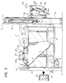
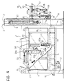
- Figures 3 and 4 are partially-sectioned side views of the slicing machine in two different working conditions,
- Figure 5 is a front view of the slicing machine, and
- Figures 6 and 7 are partially-sectioned side views showing the guillotine-like cutting device in two different operating conditions.
- With reference to the drawings, a slicing machine according to the invention comprises a substantially tunnel-shaped support structure 1 with an inlet opening 2 (Figure 2) and an
outlet portal 3. - In the embodiment illustrated, at least one side wall of the tunnel-shaped support structure 1 has a plurality of holes or windows 4 with which respective
transparent closure doors 5, for example, glazed doors, are associated. - The
outlet portal 3 is defined by a pair of hollowvertical uprights 6 surmounted by across member 7. - The lower ends of the
uprights 6 are connected by a reinforcing cross member 8 (Figures 1 and 5). - The
uprights 6 of theoutlet portal 3 are somewhat taller than the top of the tunnel-shaped support structure 1. - In the bottom of said tunnel-shaped structure there is a belt conveyor, generally indicated 9 in Figure 2. This conveyor comprises an endless belt or piece of
fabric 10 which is stretched betweenrollers 11 to 16 and is moved by anelectric motor 17 fixed to the support structure 1. In use, the activation of the motor moves the fabric orbelt 10 so that its upper pass moves from the inlet opening of the support structure 2 towards theoutlet portal 3, as indicated by the arrow F1 in Figure 2. - A
carriage 18 is movable in the tunnel-shaped structure 1 above the belt conveyor 9 and, in the embodiment shown (Figure 2), comprises twolateral arms 18a joined together by across member 18b. This carriage is movable within the support structure 1 between the inlet opening 2 and theportal 3, parallel to the conveyor belt 9, by the operation of a drive system which comprises anelectric motor 19 and associatedtransmission chains 20 extending betweensprockets 21. -
Respective drive cylinders 22 are connected to thelateral arms 18a of thecarriage 18. The rod of each cylinder is articulated to afirst end 23a of anarm 23 which can pivot relative to the carriage in a vertical plane parallel to the direction of movement of said carriage, about apin 24. - A
thrust member 25a is articulated between theother ends 23b of thearms 23 and extends transverse the direction of movement of thecarriage 18. In the embodiment illustrated, the thrust member is essentially prismatic in shape and has a flat thrust surface,indicated 25a in Figures 2 to 4. - A further electric motor carried by a
lateral arm 18a of thecarriage 18 is indicated 26 in Figure 2 and, by means of a transmission chain 27 (Figures 2 and 4), can rotate asprocket 28 which is fixed to thethrust member 25 and is coaxial with the axis of articulation of the latter to theends 23b of the pivotingarms 23. - In operation, the coordinated operation of the
cylinders 22 and of theelectric motor 26 moves the pivotingarms 23 and thethrust member 25 from the raised position of Figure 3 to the lowered position shown in Figures 2 and 4. - In the raised position (Figure 3), the
portions 23b of the pivotingarms 23 extend parallel to and adjacent thelateral arms 18a of thecarriage 18 and thethrust member 25 extends above the plane of the carriage with itsthrust surface 25a facing upwardly. - In the lowered position (Figures 2 and 4), the
portions 23b of the pivotingarms 23 extend downwardly beneath the general plane of thecarriage 18 towards theconveyor belt 10 and thethrust member 25 extends a short distance from theconveyor belt 10 and is oriented with itsthrust surface 25a parallel to and facing theoutlet portal 3. - The
thrust member 25 can be moved from the position of Figure 3 to the position of Figure 4 by the pivoting of the arms 23 (by means of the cylinders 22) in combination with a simultaneous pivoting of thethrust member 25 about its axis of articulation to said arms (brought about by the operation of the electric motor 26). - Two strong drive cylinders, indicated 30 in Figures 2 to 5, are fixed in the upper portions of the
uprights 6 of theoutlet portal 3. - The lower ends of said rods of these cylinders are connected to a guillotine-like cutting device, generally indicated 40 in Figure 2. This device comprises a
plate 41 the bottom of which is connected to acutting blade 42. The vertical sides of theplate 41 are connected to twoarms 43, the lower ends of which are connected to the rods of thecylinders 30. - The
plate 41 and the associatedcutting blade 42 can be moved by means of thecylinders 30 between the raised position shown in Figures 2 to 5 and a lowered, cutting position (not shown). - A compressor device associated with the unit formed by the
plate 41 and thecutting blade 42 is generally indicated 70 in Figures 2, 5, 6 and 7. This device comprises a horizontaltransverse pressure member 71, the ends of which are connected to the lower portions of twovertical arms 72, the outer sides of the top portions of which carry guide rollers 73 (Figures 5 to 7) which can run in vertical guides 74 (Figures 6 and 7) carried by theuprights 6 of theportal 3. - The upper ends of the
arms 72 haverespective bent tabs 72a (Figures 2, 6 and 7) for bearing on the upper edge of theplate 41. - The
compressor device 70 is disposed immediately upstream of theplate 41 and the associatedblade 42 and can move vertically, together with saidplate 41, as a result of the operation of thecylinders 30. This device is not fixed to said plate, however, so that it can, in fact, be entrained upwardly by this plate when the plate is raised by thecylinders 30 and fall by gravity when said plate is lowered, until it bears on and compresses an underlying bale of tobacco B extending through theportal 3 whilst theplate 41 and theblade 42, which are entrained further downwards by thecylinders 30, penetrate the bale (Figure 7). - An abutment device connected to the
outlet portal 3 downstream of the guillotine-like cutting device 40 is generally indicated 50 in the drawings. This abutment device comprises a substantially tank-like casing 51 disposed with its opening facing inwardly of the tunnel-shaped support structure 1. - A
stop member 52, movable in thecasing 51, has afront wall 52a which is oriented vertically and faces inwardly of the tunnel-shaped structure 1. - This stop member is movable away from and towards the guillotine-like cutting device in the directions indicated by the arrows F3 in Figures 2 and 4, along guide rails 54 (Figures 3 and 4) in the
casing 51. - In the embodiment shown, the
stop member 52 can be moved by means of adrive cylinder 55 the top of which is articulated to thecasing 51 and the rod of which is articulated to anoperating arm 56 of a kinematic mechanism connected to themember 52. This kinematic mechanism comprises a shaft 57 (Figure 2) which can rotate in thecasing 51 and to which thearm 56, as well as two further arms orcranks 58 connected to themember 52 by means of respective articulated connectingrods 59, are fixed torsionally. - The slicing machine described above operates in the following manner.
- A bale of tobacco, indicated B in Figures 3 and 4, is introduced into the tunnel-shaped structure 1 through its inlet opening 2 as indicated in Figure 3. This bale may be introduced manually or may be supplied to the slicing machine, for example, by means of conveyor devices, not shown.
- In this condition, the machine assumes the configuration shown in Figure 3, in which the
thrust member 25 is in the raised position and does not obstruct the transfer of the bale B towards theoutlet portal 3 by theconveyor belt 10. Theplate 41 and the associatedcutting blade 42 are in the raised position, so that the bale B is carried through theportal 3 by thebelt 10 until it stops against thestop surface 52a of theabutment device 50 as shown in Figure 4. - The coordinated operation of the
cylinders 22 and of theelectric motor 26 associated with thecarriage 18 then move thethrust member 25 towards the lowered position shown in Figure 4. The operation of theelectric motor 19 also moves thecarriage 18 towards the outlet portal until thethrust surface 25a of themember 25 is brought to bear against the rear end face of the bale B. At this point, the activation of thecylinders 30 causes a downward movement of thecutting blade 42 and of thecompressor device 70 which, by means of itstransverse pressure member 71, compacts the bale, which is then penetrated by said blade. The slice between the path of this blade and thestop surface 52a of thestop member 52 is thus cut. - The
blade 42 and the associatedplate 41 are then returned to the raised position by means of thecylinders 30. This plate entrains thecompressor device 70 and raises it again. The coordinated operation of theelectric motor 19 and thedrive cylinder 55 then moves thethrust member 25 towards theportal 3 and retracts thestop member 52 within thecasing 51 until the slice previously cut is free to fall downwards by gravity where conveyor devices may be provided for collecting it and moving it away from the slicing machine. - The
stop member 52 of theabutment device 50 is then advanced towards theportal 3 again until it reaches its working position at a distance D from the path of thecutting blade 42, this distance corresponding to the thickness of the slices into which the bale B is to be divided. - The bale B is brought against the
surface 52a of thestop member 52 again as a result of a further movement of thethrust member 25 towards theoutlet portal 3. - The
cutting blade 42 is then lowered again in order to cut another slice. The operation proceeds in the manner described above until the tobacco bale B has been used up, after which the slicing machine is returned to its initial configuration and the operation recommences with the supply of a further bale of tobacco through its inlet portal 2. - Conveniently, in order to facilitate inspection and any maintenance or repairs of the guillotine-like cutting device, the
support casing 51 of theabutment device 50 is connected to one of theuprights 6 of theportal 3 by means of hinges 60 (Figure 1) which enable it to pivot in a horizontal plane after the release of locking means 61 which connect it releasably to the other upright of the portal. - The coordinated operation of the various electric motors and of the various operating cylinders of the machine may be achieved in known manner by means of a control unit, not shown.
- Naturally, the principle of the invention remaining the same, the forms of embodiment and details of construction may be varied widely with respect to those described and illustrated purely by way of non-limiting example, without thereby departing from the scope of the present invention.
Claims (9)
- A slicing machine, particularly for bales of tobacco (B), characterized in that it comprises:
a support structure (1) with an inlet opening (2) for the insertion of a bale (B), and with an outlet portal (3),
a conveyor (9, 10) for transferring a bale (B) from said inlet opening (2) to the outlet portal (3),
a guillotine-like cutting device (40-42; 30) in said outlet portal (3), comprising a cutting blade (42) which is movable between a raised position in which it allows a bale (B) carried by the conveyor (9, 10) to pass through the outlet portal (3) and a lowered, cutting position,
a thrust device (18-25) movable in said structure (1), above the conveyor (9, 10), and comprising a thrust member (25) which can bear against the rear end surface of the bale (B) carried by the conveyor (9, 10) and can urge it towards and through the outlet portal (3) in a controlled manner, and
an abutment device (50) associated with the outlet portal (3), downstream of the cutting device (40-42; 30), and comprising a movable stop member (52) which can assume a working position in which it defines a position where the bale (B) advancing through the outlet portal (3) in use is stopped at a predetermined distance (D) from the path of the cutting blade (42), the distance corresponding to the desired thickness of the slices to be cut. - A slicing machine according to Claim 1, characterized in that the thrust device comprises:
a motor-driven carriage (18, 19) disposed above said conveyor (9, 10) and movable away from and towards the outlet portal (3),
at least one arm (23) articulated to said carriage (18) and pivotable in a vertical plane parallel to the direction of movement of the carriage (18),
a thrust member (25) which extends transverse the direction of movement of the carriage (18) and is connected to said arm (23), and
first motor means (22, 26) which are carried by the carriage (18) and can pivot said arm (23) between a raised, rest position (Figure 3) in which the thrust member (25) extends above the path of the bales (B) carried by the conveyor (9, 10) and a lowered, working position (Figure 4) in which the thrust member (25) can be brought to bear against the rear end surface of a bale (B) carried by said conveyor (9, 10). - A slicing machine according to Claim 2, characterized in that said thrust member (25) is articulated to said at least one arm (23) for pivoting about a horizontal axis perpendicular to the direction of movement of the carriage (18), and in that second motor means (26) on the carriage (18) can pivot the thrust member (25) about said axis.
- A slicing machine according to any one of the preceding claims, characterized in that said abutment device (50) comprises:
a support casing (51) connected to said outlet portal (3), and
third motor means (55) for moving the stop member (52) away from and towards the path of the cutting blade (42). - A slicing machine according to Claim 4, characterized in that the support casing (51) of the abutment device (50) is connected pivotably to the outlet portal (3).
- A slicing machine according to any one of the preceding claims, characterized in that a compressor device (70-74) associated with said guillotine-like cutting device (40-42; 30) can compact a bale of tobacco (B) adjacent the path of said cutting blade (42).
- A slicing machine according to Claim 6, characterized in that said compressor device comprises a pressure member (71, 72) which is coupled to the cutting blade (42) in a manner such that it can fall by gravity from a raised position when said blade (42) is lowered and can be raised again by being entrained by said blade (42) when the latter is raised.
- A slicing machine according to any one of the preceding claims, characterized in that said support structure (1) is substantially tunnel-shaped and has at least one side wall (5) which is at least partially transparent.
- A slicing machine according to Claim 8, characterized in that it has openable inspection windows (5) in at least one side wall of said tunnel-shaped support structure (1).
Applications Claiming Priority (2)
| Application Number | Priority Date | Filing Date | Title |
|---|---|---|---|
| ITTO920671 | 1992-08-03 | ||
| ITTO920671A IT1256913B (en) | 1992-08-03 | 1992-08-03 | SLICING MACHINE, PARTICULARLY FOR TOBACCO BALES. |
Publications (2)
| Publication Number | Publication Date |
|---|---|
| EP0582139A1 true EP0582139A1 (en) | 1994-02-09 |
| EP0582139B1 EP0582139B1 (en) | 1998-09-02 |
Family
ID=11410664
Family Applications (1)
| Application Number | Title | Priority Date | Filing Date |
|---|---|---|---|
| EP93111734A Expired - Lifetime EP0582139B1 (en) | 1992-08-03 | 1993-07-22 | A slicing machine, particularly for bales of tobacco |
Country Status (9)
| Country | Link |
|---|---|
| US (1) | US5435218A (en) |
| EP (1) | EP0582139B1 (en) |
| JP (1) | JPH06165664A (en) |
| AT (1) | ATE170367T1 (en) |
| AU (1) | AU656684B2 (en) |
| DE (1) | DE69320736T2 (en) |
| DK (1) | DK0582139T3 (en) |
| ES (1) | ES2123020T3 (en) |
| IT (1) | IT1256913B (en) |
Cited By (9)
| Publication number | Priority date | Publication date | Assignee | Title |
|---|---|---|---|---|
| EP0699395A2 (en) | 1994-08-25 | 1996-03-06 | Hauni Maschinenbau Aktiengesellschaft | Apparatus for slicing bales |
| EP1502511A2 (en) * | 2003-07-28 | 2005-02-02 | Hauni Maschinenbau AG | Delamination of tobacco bales |
| CN104273645A (en) * | 2013-07-09 | 2015-01-14 | 豪尼机械制造股份公司 | Constructing and setting apparatus used for automatically cutting slices on material pack formed by materials in tobacco processing industry |
| CN105014715A (en) * | 2014-04-13 | 2015-11-04 | 胡刘满 | Quick slicing poria machine |
| CN106108101A (en) * | 2016-08-26 | 2016-11-16 | 红塔烟草(集团)有限责任公司 | A kind of adjustable tobacco carving knife machine |
| CN106614874A (en) * | 2017-01-27 | 2017-05-10 | 成都蒲江珂贤科技有限公司 | Device for spicy strip cutting and seasoning spreading |
| CN109452683A (en) * | 2018-12-06 | 2019-03-12 | 阜阳市卓创科技服务生产力促进中心 | A kind of cigarette raw material processing cutting equipment and its cutting method |
| CN113146706A (en) * | 2021-04-08 | 2021-07-23 | 刘英海 | Contactless gauze mask recovery destroying device |
| WO2023191744A1 (en) * | 2022-03-31 | 2023-10-05 | Adeba Mühendi̇sli̇k Danişmanlik Halkla İli̇şki̇ler İnşaat Sanayi̇ Ve Ti̇caret Anoni̇m Şi̇rketi̇ | A system having a robotic functionality for a division process of a pressed and cased tobacco bale inside its original case into 2 or more pieces |
Families Citing this family (16)
| Publication number | Priority date | Publication date | Assignee | Title |
|---|---|---|---|---|
| US5938580A (en) * | 1994-04-15 | 1999-08-17 | Ranpak Corp. | Cushioning conversion machine with restricted access to a cutting assembly |
| US5542325A (en) * | 1994-08-30 | 1996-08-06 | Bane, Iii; Wiliam W. | Sheet cutting apparatus |
| US5598757A (en) * | 1995-02-02 | 1997-02-04 | Lucent Technologies Inc. | Method for shearing panels |
| EP0958135A1 (en) | 1996-06-28 | 1999-11-24 | Ranpak Corp. | Cushioning conversion machine |
| EP0867126B1 (en) * | 1996-07-11 | 2003-10-01 | Japan Tobacco Inc. | Apparatus for slicing compression molded product of sheet-shaped material and split knife |
| US6053084A (en) * | 1998-11-13 | 2000-04-25 | Lucent Technologies, Inc. | System and method for cutting panels |
| US20050268765A1 (en) * | 2004-06-04 | 2005-12-08 | Chun-Jen Chien | Reciprocal bi-directional table saw |
| KR100785817B1 (en) | 2007-01-17 | 2007-12-13 | (유)대도 | Cutting apparatus for livestock feed |
| CN102907754A (en) * | 2011-08-03 | 2013-02-06 | 湖北中烟工业有限责任公司 | Vertical stripping machine |
| CN103478880B (en) * | 2013-10-11 | 2015-12-23 | 龙岩烟草工业有限责任公司 | Smoked sheet extruding aeration apparatus and technique thereof |
| CN103783655A (en) * | 2014-02-25 | 2014-05-14 | 湖南省烟草公司永州市公司 | Hand hay cutter type tobacco clamping and petiole cutting operation table |
| CN105171830B (en) * | 2014-04-13 | 2017-05-31 | 梁丽珠 | A kind of equipment for the section of ball fungus medicinal material |
| CN104400808B (en) * | 2014-10-23 | 2016-08-24 | 湖南皇爷食品有限公司 | A kind of areca-cutting machine |
| CN104824819B (en) * | 2015-04-01 | 2017-01-25 | 安徽中烟机械有限公司 | Entire cigarette packet feeding and tobacco leaf tobacco petiole cutting separation pre-loosening device |
| CN106418657B (en) * | 2016-09-26 | 2017-08-25 | 湖北中烟工业有限责任公司 | A kind of cutting, the device of stable Lamina bale |
| CN111329101B (en) * | 2019-12-18 | 2022-04-19 | 湖北中烟工业有限责任公司 | Accurate control system of slicer based on machine vision detection technique |
Citations (5)
| Publication number | Priority date | Publication date | Assignee | Title |
|---|---|---|---|---|
| DE1139419B (en) * | 1960-09-20 | 1962-11-08 | Reemtsma H F & Ph | Device for severing slices from a tobacco bale |
| EP0159836A1 (en) * | 1984-04-02 | 1985-10-30 | W.H. Dickinson Engineering Limited | Sliced bale conditioning |
| WO1987002868A1 (en) * | 1985-11-13 | 1987-05-21 | Gbe International Plc | A tobacco block slicing machine |
| GB2246279A (en) * | 1990-07-28 | 1992-01-29 | Koerber Ag | Method of and apparatus for breaking up bales of condensed tobacco |
| EP0511196A1 (en) * | 1991-04-26 | 1992-10-28 | SCHIFF & STERN KG | Device for the transport and the separation of slices from tobacco bales |
Family Cites Families (4)
| Publication number | Priority date | Publication date | Assignee | Title |
|---|---|---|---|---|
| US2207754A (en) * | 1938-12-31 | 1940-07-16 | Edward J Neary | Apparatus for slicing meats and other food products |
| US3180195A (en) * | 1960-10-10 | 1965-04-27 | Clark Julius | Apparatus for removing thermoplastic material from containers |
| JPS5929226B2 (en) * | 1981-11-11 | 1984-07-19 | 日本たばこ産業株式会社 | split feeding device |
| US5152208A (en) * | 1989-12-29 | 1992-10-06 | K. S. Macey Machine Company, Inc. | Book feeding and trimming apparatus |
-
1992
- 1992-08-03 IT ITTO920671A patent/IT1256913B/en active IP Right Grant
-
1993
- 1993-07-22 AT AT93111734T patent/ATE170367T1/en active
- 1993-07-22 EP EP93111734A patent/EP0582139B1/en not_active Expired - Lifetime
- 1993-07-22 ES ES93111734T patent/ES2123020T3/en not_active Expired - Lifetime
- 1993-07-22 DE DE69320736T patent/DE69320736T2/en not_active Expired - Lifetime
- 1993-07-22 DK DK93111734T patent/DK0582139T3/en active
- 1993-07-26 US US08/097,779 patent/US5435218A/en not_active Expired - Lifetime
- 1993-07-28 AU AU44230/93A patent/AU656684B2/en not_active Ceased
- 1993-07-30 JP JP5208225A patent/JPH06165664A/en active Pending
Patent Citations (5)
| Publication number | Priority date | Publication date | Assignee | Title |
|---|---|---|---|---|
| DE1139419B (en) * | 1960-09-20 | 1962-11-08 | Reemtsma H F & Ph | Device for severing slices from a tobacco bale |
| EP0159836A1 (en) * | 1984-04-02 | 1985-10-30 | W.H. Dickinson Engineering Limited | Sliced bale conditioning |
| WO1987002868A1 (en) * | 1985-11-13 | 1987-05-21 | Gbe International Plc | A tobacco block slicing machine |
| GB2246279A (en) * | 1990-07-28 | 1992-01-29 | Koerber Ag | Method of and apparatus for breaking up bales of condensed tobacco |
| EP0511196A1 (en) * | 1991-04-26 | 1992-10-28 | SCHIFF & STERN KG | Device for the transport and the separation of slices from tobacco bales |
Cited By (16)
| Publication number | Priority date | Publication date | Assignee | Title |
|---|---|---|---|---|
| EP0699395A2 (en) | 1994-08-25 | 1996-03-06 | Hauni Maschinenbau Aktiengesellschaft | Apparatus for slicing bales |
| EP0699395A3 (en) * | 1994-08-25 | 1999-01-27 | Hauni Maschinenbau Aktiengesellschaft | Apparatus for slicing bales |
| EP1502511A2 (en) * | 2003-07-28 | 2005-02-02 | Hauni Maschinenbau AG | Delamination of tobacco bales |
| EP1502511A3 (en) * | 2003-07-28 | 2005-04-13 | Hauni Maschinenbau AG | Delamination of tobacco bales |
| CN104273645B (en) * | 2013-07-09 | 2018-07-20 | 虹霓机械制造有限公司 | It constructs and sets up the device for automatically wrapping segmentation slice from the material being made of the material of the tobacco industry |
| DE102013107248A1 (en) | 2013-07-09 | 2015-01-15 | Hauni Maschinenbau Ag | Apparatus, adapted and arranged for automatically separating slices from a bale made of material from the tobacco processing industry |
| EP2848132A1 (en) | 2013-07-09 | 2015-03-18 | Hauni Maschinenbau AG | Device, designed and set up for the automatic separation of discs from bales of material in the tobacco processing industry |
| DE102013107248B4 (en) * | 2013-07-09 | 2016-05-25 | Hauni Maschinenbau Ag | Apparatus, adapted and arranged for automatically separating slices from a bale made of material from the tobacco processing industry |
| CN104273645A (en) * | 2013-07-09 | 2015-01-14 | 豪尼机械制造股份公司 | Constructing and setting apparatus used for automatically cutting slices on material pack formed by materials in tobacco processing industry |
| CN105014715A (en) * | 2014-04-13 | 2015-11-04 | 胡刘满 | Quick slicing poria machine |
| CN105014714A (en) * | 2014-04-13 | 2015-11-04 | 胡刘满 | Novel mechanical device for rapid slicing |
| CN106108101A (en) * | 2016-08-26 | 2016-11-16 | 红塔烟草(集团)有限责任公司 | A kind of adjustable tobacco carving knife machine |
| CN106614874A (en) * | 2017-01-27 | 2017-05-10 | 成都蒲江珂贤科技有限公司 | Device for spicy strip cutting and seasoning spreading |
| CN109452683A (en) * | 2018-12-06 | 2019-03-12 | 阜阳市卓创科技服务生产力促进中心 | A kind of cigarette raw material processing cutting equipment and its cutting method |
| CN113146706A (en) * | 2021-04-08 | 2021-07-23 | 刘英海 | Contactless gauze mask recovery destroying device |
| WO2023191744A1 (en) * | 2022-03-31 | 2023-10-05 | Adeba Mühendi̇sli̇k Danişmanlik Halkla İli̇şki̇ler İnşaat Sanayi̇ Ve Ti̇caret Anoni̇m Şi̇rketi̇ | A system having a robotic functionality for a division process of a pressed and cased tobacco bale inside its original case into 2 or more pieces |
Also Published As
| Publication number | Publication date |
|---|---|
| ITTO920671A0 (en) | 1992-08-03 |
| US5435218A (en) | 1995-07-25 |
| JPH06165664A (en) | 1994-06-14 |
| ITTO920671A1 (en) | 1994-02-03 |
| IT1256913B (en) | 1995-12-27 |
| AU656684B2 (en) | 1995-02-09 |
| DE69320736D1 (en) | 1998-10-08 |
| DK0582139T3 (en) | 1999-05-31 |
| ATE170367T1 (en) | 1998-09-15 |
| EP0582139B1 (en) | 1998-09-02 |
| AU4423093A (en) | 1994-02-10 |
| DE69320736T2 (en) | 1999-05-06 |
| ES2123020T3 (en) | 1999-01-01 |
Similar Documents
| Publication | Publication Date | Title |
|---|---|---|
| US5435218A (en) | Slicing machine | |
| AT390433B (en) | DEVICE FOR APPLYING FLEXIBLE SPACERS | |
| US4444077A (en) | Flying saw apparatus | |
| JPH04500635A (en) | Equipment for cutting stacked sheet materials | |
| EP1260327B1 (en) | Slicing machine with cutting device for film or paper | |
| KR100769565B1 (en) | High speed fresh meat slicer | |
| GB2118881A (en) | Method and apparatus for cutting continuous corrugated member | |
| CA2514864C (en) | Bread slicer | |
| US2824610A (en) | Mat segregating mechanism and methods | |
| CN219929190U (en) | Pile up neatly device is pasted to magic | |
| CN109203116A (en) | Integrated timber system of processing | |
| DE2430043A1 (en) | Cutting out for paper stacks or book pads - individual stacks clamped on continually moving supports prior to cutting | |
| DE2520098C3 (en) | Device for cutting brittle sheet material | |
| DE2841386A1 (en) | DEVICE FOR AUTOMATIC CUTTING OF RAIL MATERIAL | |
| CN109548538A (en) | Apple fast bagging system and method | |
| CN113977660A (en) | Cutting device for composite board production | |
| DE602004004946T2 (en) | BELT DRIVE ARRANGEMENT FOR A TANK TEST MACHINE | |
| CN220450041U (en) | Glass fiber cutter | |
| CN219190315U (en) | Device is cut with high efficiency to aquatic products processing | |
| CN219854720U (en) | Toast slicer with adjustable slice thickness | |
| CN217701592U (en) | Pressing device for iron core transverse shearing | |
| JPS601933Y2 (en) | Cutting device for long bar materials | |
| US1935996A (en) | Bread slicing machine | |
| CN220362632U (en) | Safety medicine cutting machine | |
| CN217971472U (en) | Equidistant pull-open mechanism |
Legal Events
| Date | Code | Title | Description |
|---|---|---|---|
| PUAI | Public reference made under article 153(3) epc to a published international application that has entered the european phase |
Free format text: ORIGINAL CODE: 0009012 |
|
| AK | Designated contracting states |
Kind code of ref document: A1 Designated state(s): AT BE CH DE DK ES FR GB GR IE IT LI LU MC NL PT SE |
|
| 17P | Request for examination filed |
Effective date: 19940714 |
|
| 17Q | First examination report despatched |
Effective date: 19951120 |
|
| GRAG | Despatch of communication of intention to grant |
Free format text: ORIGINAL CODE: EPIDOS AGRA |
|
| GRAG | Despatch of communication of intention to grant |
Free format text: ORIGINAL CODE: EPIDOS AGRA |
|
| GRAH | Despatch of communication of intention to grant a patent |
Free format text: ORIGINAL CODE: EPIDOS IGRA |
|
| GRAH | Despatch of communication of intention to grant a patent |
Free format text: ORIGINAL CODE: EPIDOS IGRA |
|
| GRAA | (expected) grant |
Free format text: ORIGINAL CODE: 0009210 |
|
| AK | Designated contracting states |
Kind code of ref document: B1 Designated state(s): AT BE CH DE DK ES FR GB GR IE IT LI LU MC NL PT SE |
|
| REF | Corresponds to: |
Ref document number: 170367 Country of ref document: AT Date of ref document: 19980915 Kind code of ref document: T |
|
| REG | Reference to a national code |
Ref country code: CH Ref legal event code: NV Representative=s name: JACOBACCI & PERANI S.A. Ref country code: CH Ref legal event code: EP |
|
| REF | Corresponds to: |
Ref document number: 69320736 Country of ref document: DE Date of ref document: 19981008 |
|
| REG | Reference to a national code |
Ref country code: IE Ref legal event code: FG4D |
|
| ET | Fr: translation filed | ||
| REG | Reference to a national code |
Ref country code: PT Ref legal event code: SC4A Free format text: AVAILABILITY OF NATIONAL TRANSLATION Effective date: 19980903 |
|
| REG | Reference to a national code |
Ref country code: ES Ref legal event code: FG2A Ref document number: 2123020 Country of ref document: ES Kind code of ref document: T3 |
|
| REG | Reference to a national code |
Ref country code: DK Ref legal event code: T3 |
|
| PLBE | No opposition filed within time limit |
Free format text: ORIGINAL CODE: 0009261 |
|
| STAA | Information on the status of an ep patent application or granted ep patent |
Free format text: STATUS: NO OPPOSITION FILED WITHIN TIME LIMIT |
|
| 26N | No opposition filed | ||
| PGFP | Annual fee paid to national office [announced via postgrant information from national office to epo] |
Ref country code: SE Payment date: 20010529 Year of fee payment: 9 |
|
| PGFP | Annual fee paid to national office [announced via postgrant information from national office to epo] |
Ref country code: DK Payment date: 20010612 Year of fee payment: 9 |
|
| PGFP | Annual fee paid to national office [announced via postgrant information from national office to epo] |
Ref country code: MC Payment date: 20010620 Year of fee payment: 9 |
|
| PGFP | Annual fee paid to national office [announced via postgrant information from national office to epo] |
Ref country code: PT Payment date: 20010625 Year of fee payment: 9 |
|
| PGFP | Annual fee paid to national office [announced via postgrant information from national office to epo] |
Ref country code: GR Payment date: 20010627 Year of fee payment: 9 |
|
| REG | Reference to a national code |
Ref country code: GB Ref legal event code: IF02 |
|
| PG25 | Lapsed in a contracting state [announced via postgrant information from national office to epo] |
Ref country code: SE Free format text: LAPSE BECAUSE OF NON-PAYMENT OF DUE FEES Effective date: 20020723 |
|
| PG25 | Lapsed in a contracting state [announced via postgrant information from national office to epo] |
Ref country code: DK Free format text: LAPSE BECAUSE OF NON-PAYMENT OF DUE FEES Effective date: 20020731 |
|
| PG25 | Lapsed in a contracting state [announced via postgrant information from national office to epo] |
Ref country code: PT Free format text: LAPSE BECAUSE OF NON-PAYMENT OF DUE FEES Effective date: 20030131 |
|
| PG25 | Lapsed in a contracting state [announced via postgrant information from national office to epo] |
Ref country code: MC Free format text: LAPSE BECAUSE OF NON-PAYMENT OF DUE FEES Effective date: 20030201 |
|
| PG25 | Lapsed in a contracting state [announced via postgrant information from national office to epo] |
Ref country code: GR Free format text: LAPSE BECAUSE OF NON-PAYMENT OF DUE FEES Effective date: 20030206 |
|
| EUG | Se: european patent has lapsed | ||
| REG | Reference to a national code |
Ref country code: DK Ref legal event code: EBP |
|
| REG | Reference to a national code |
Ref country code: PT Ref legal event code: MM4A Free format text: LAPSE DUE TO NON-PAYMENT OF FEES Effective date: 20030131 |
|
| PGFP | Annual fee paid to national office [announced via postgrant information from national office to epo] |
Ref country code: CH Payment date: 20120529 Year of fee payment: 20 |
|
| PGFP | Annual fee paid to national office [announced via postgrant information from national office to epo] |
Ref country code: LU Payment date: 20120720 Year of fee payment: 20 |
|
| PGFP | Annual fee paid to national office [announced via postgrant information from national office to epo] |
Ref country code: IE Payment date: 20120719 Year of fee payment: 20 Ref country code: GB Payment date: 20120719 Year of fee payment: 20 |
|
| PGFP | Annual fee paid to national office [announced via postgrant information from national office to epo] |
Ref country code: BE Payment date: 20120720 Year of fee payment: 20 Ref country code: FR Payment date: 20120816 Year of fee payment: 20 Ref country code: IT Payment date: 20120716 Year of fee payment: 20 Ref country code: ES Payment date: 20120530 Year of fee payment: 20 |
|
| PGFP | Annual fee paid to national office [announced via postgrant information from national office to epo] |
Ref country code: DE Payment date: 20121001 Year of fee payment: 20 Ref country code: NL Payment date: 20120727 Year of fee payment: 20 |
|
| PGFP | Annual fee paid to national office [announced via postgrant information from national office to epo] |
Ref country code: AT Payment date: 20120726 Year of fee payment: 20 |
|
| REG | Reference to a national code |
Ref country code: DE Ref legal event code: R071 Ref document number: 69320736 Country of ref document: DE |
|
| BE20 | Be: patent expired |
Owner name: *COMAS S.P.A. Effective date: 20130722 |
|
| REG | Reference to a national code |
Ref country code: NL Ref legal event code: V4 Effective date: 20130722 Ref country code: CH Ref legal event code: PL |
|
| REG | Reference to a national code |
Ref country code: GB Ref legal event code: PE20 Expiry date: 20130721 |
|
| REG | Reference to a national code |
Ref country code: AT Ref legal event code: MK07 Ref document number: 170367 Country of ref document: AT Kind code of ref document: T Effective date: 20130722 |
|
| REG | Reference to a national code |
Ref country code: ES Ref legal event code: FD2A Effective date: 20131018 |
|
| PG25 | Lapsed in a contracting state [announced via postgrant information from national office to epo] |
Ref country code: DE Free format text: LAPSE BECAUSE OF EXPIRATION OF PROTECTION Effective date: 20130723 Ref country code: ES Free format text: LAPSE BECAUSE OF EXPIRATION OF PROTECTION Effective date: 20130723 |
|
| PG25 | Lapsed in a contracting state [announced via postgrant information from national office to epo] |
Ref country code: GB Free format text: LAPSE BECAUSE OF EXPIRATION OF PROTECTION Effective date: 20130721 |
|
| REG | Reference to a national code |
Ref country code: IE Ref legal event code: MK9A |
|
| PG25 | Lapsed in a contracting state [announced via postgrant information from national office to epo] |
Ref country code: IE Free format text: LAPSE BECAUSE OF EXPIRATION OF PROTECTION Effective date: 20130722 |