EP0578340A2 - Entwicklungsvorrichtung - Google Patents
Entwicklungsvorrichtung Download PDFInfo
- Publication number
- EP0578340A2 EP0578340A2 EP19930202773 EP93202773A EP0578340A2 EP 0578340 A2 EP0578340 A2 EP 0578340A2 EP 19930202773 EP19930202773 EP 19930202773 EP 93202773 A EP93202773 A EP 93202773A EP 0578340 A2 EP0578340 A2 EP 0578340A2
- Authority
- EP
- European Patent Office
- Prior art keywords
- main body
- cartridge
- developing device
- toner
- cover member
- Prior art date
- Legal status (The legal status is an assumption and is not a legal conclusion. Google has not performed a legal analysis and makes no representation as to the accuracy of the status listed.)
- Granted
Links
Images


Classifications
-
- G—PHYSICS
- G03—PHOTOGRAPHY; CINEMATOGRAPHY; ANALOGOUS TECHNIQUES USING WAVES OTHER THAN OPTICAL WAVES; ELECTROGRAPHY; HOLOGRAPHY
- G03G—ELECTROGRAPHY; ELECTROPHOTOGRAPHY; MAGNETOGRAPHY
- G03G15/00—Apparatus for electrographic processes using a charge pattern
- G03G15/06—Apparatus for electrographic processes using a charge pattern for developing
- G03G15/08—Apparatus for electrographic processes using a charge pattern for developing using a solid developer, e.g. powder developer
- G03G15/0896—Arrangements or disposition of the complete developer unit or parts thereof not provided for by groups G03G15/08 - G03G15/0894
-
- G—PHYSICS
- G03—PHOTOGRAPHY; CINEMATOGRAPHY; ANALOGOUS TECHNIQUES USING WAVES OTHER THAN OPTICAL WAVES; ELECTROGRAPHY; HOLOGRAPHY
- G03G—ELECTROGRAPHY; ELECTROPHOTOGRAPHY; MAGNETOGRAPHY
- G03G15/00—Apparatus for electrographic processes using a charge pattern
- G03G15/06—Apparatus for electrographic processes using a charge pattern for developing
- G03G15/08—Apparatus for electrographic processes using a charge pattern for developing using a solid developer, e.g. powder developer
- G03G15/0822—Arrangements for preparing, mixing, supplying or dispensing developer
- G03G15/0848—Arrangements for testing or measuring developer properties or quality, e.g. charge, size, flowability
- G03G15/0849—Detection or control means for the developer concentration
- G03G15/0855—Detection or control means for the developer concentration the concentration being measured by optical means
-
- G—PHYSICS
- G03—PHOTOGRAPHY; CINEMATOGRAPHY; ANALOGOUS TECHNIQUES USING WAVES OTHER THAN OPTICAL WAVES; ELECTROGRAPHY; HOLOGRAPHY
- G03G—ELECTROGRAPHY; ELECTROPHOTOGRAPHY; MAGNETOGRAPHY
- G03G15/00—Apparatus for electrographic processes using a charge pattern
- G03G15/06—Apparatus for electrographic processes using a charge pattern for developing
- G03G15/08—Apparatus for electrographic processes using a charge pattern for developing using a solid developer, e.g. powder developer
- G03G15/0822—Arrangements for preparing, mixing, supplying or dispensing developer
- G03G15/0865—Arrangements for supplying new developer
- G03G15/0875—Arrangements for supplying new developer cartridges having a box like shape
-
- G—PHYSICS
- G03—PHOTOGRAPHY; CINEMATOGRAPHY; ANALOGOUS TECHNIQUES USING WAVES OTHER THAN OPTICAL WAVES; ELECTROGRAPHY; HOLOGRAPHY
- G03G—ELECTROGRAPHY; ELECTROPHOTOGRAPHY; MAGNETOGRAPHY
- G03G15/00—Apparatus for electrographic processes using a charge pattern
- G03G15/06—Apparatus for electrographic processes using a charge pattern for developing
- G03G15/08—Apparatus for electrographic processes using a charge pattern for developing using a solid developer, e.g. powder developer
- G03G15/0822—Arrangements for preparing, mixing, supplying or dispensing developer
- G03G15/0877—Arrangements for metering and dispensing developer from a developer cartridge into the development unit
- G03G15/0881—Sealing of developer cartridges
- G03G15/0886—Sealing of developer cartridges by mechanical means, e.g. shutter, plug
-
- G—PHYSICS
- G03—PHOTOGRAPHY; CINEMATOGRAPHY; ANALOGOUS TECHNIQUES USING WAVES OTHER THAN OPTICAL WAVES; ELECTROGRAPHY; HOLOGRAPHY
- G03G—ELECTROGRAPHY; ELECTROPHOTOGRAPHY; MAGNETOGRAPHY
- G03G15/00—Apparatus for electrographic processes using a charge pattern
- G03G15/06—Apparatus for electrographic processes using a charge pattern for developing
- G03G15/08—Apparatus for electrographic processes using a charge pattern for developing using a solid developer, e.g. powder developer
- G03G15/0822—Arrangements for preparing, mixing, supplying or dispensing developer
- G03G15/0887—Arrangements for conveying and conditioning developer in the developing unit, e.g. agitating, removing impurities or humidity
-
- G—PHYSICS
- G03—PHOTOGRAPHY; CINEMATOGRAPHY; ANALOGOUS TECHNIQUES USING WAVES OTHER THAN OPTICAL WAVES; ELECTROGRAPHY; HOLOGRAPHY
- G03G—ELECTROGRAPHY; ELECTROPHOTOGRAPHY; MAGNETOGRAPHY
- G03G2215/00—Apparatus for electrophotographic processes
- G03G2215/06—Developing structures, details
- G03G2215/066—Toner cartridge or other attachable and detachable container for supplying developer material to replace the used material
- G03G2215/0692—Toner cartridge or other attachable and detachable container for supplying developer material to replace the used material using a slidable sealing member, e.g. shutter
Definitions
- This invention relates to a developing device which can be applied to an image-forming machine such as an electrostatic copying machine and an electrostatic printing machine.
- Image-forming machines such as an electrostatic copying machine are equipped with a developing device for developing the resulting latent electrostatic image to a toner image.
- a developing device is adapted to be mounted and detached on and from the main body of the image-forming machine to facilitate maintenance of the developing device itself, or to enable the developing device to be replaced in the case of monocolor copying (see, for example, Japanese Laid-Open Patent Publication No. 229072/1985).
- a conventional developing device such as the one disclosed in the above-cited Japanese Laid-Open Patent Publication No. 229072/1985 is of such a structure as can be mounted detachably on the image-forming machine by moving it vertically. Because of this structure, the mounting and detaching operations of the developing device are not easy. Furthermore, since a space should be provided in the main body of the image-forming machine for mounting and detaching the developing device, the image-forming machine increases in size.
- a developing device of the type which is mounted movably between an operating position near an electrophotographic material at which position a developer in the developing device acts on the electrophotographic material and a non-operating position away from the electrophotographic material at which position the developer does not substantially act on the electrophotographic material, and which is brought to the above non-operating position at the time of mounting and detaching the developing device in order to avoid damage of the electrophotographic material (see, for example, Japanese Laid-Open Utility Model Publication No. 52746/1981).
- this conventional developing device is movable horizontally between the operating position and the non-operating position, a relatively large space is required for the developing device, and it is difficult to build the image-forming device with a small size.
- This improved developing device comprises a main body having a developing section equipped with applicator means for applying a developer and a supporting section for supporting the developing section rotatably between an operating position and a non-operating position, and a changeover mechanism disposed in an image-forming machine for selectively holding the developing section at the operating position and the non-operating position.
- This developing device still has defects described below.
- the developing section of the main body of the developing device is held at the above operating position by a biasing spring attached to the developing section and the own weight of the developing section. Since the biasing force of the biasing spring cannot be increased so much because of the need to permit easy mounting and detaching of the main body of the developing device, the developing section is difficult to hold exactly at the operating position.
- the supporting section should be pivoted against the biasing action of the spring at the time of mounting the main body of the developing device. Otherwise, the developing device cannot be mounted in position on the image-forming machine. Hence, the mounting operation of the main body of the developing device is somewhat complex.
- electrical connecting terminals connected releasably to each other are provided in the main body of the developing device and the main body of the image-forming machine in order to give a bias voltage to the applicator means in the developing section. Connection and releasing of the electrical connecting terminals require relatively complex operations.
- developing devices of the toner supply type which comprise a main body equipped with developer applicator means and a toner cartridge detachably mounted on the main body.
- the toner cartridge in the developing devices of this type include a cartridge body and a cover member for closing a toner supply opening formed in it.
- the cover member is attached to the toner supply opening when the cartridge body is to be detached from the main body of the developing device. This prevents scattering of the toner remaining in the cartridge body at the time of detaching.
- the cartridge body can be detached from the main body of the developing device even when the cover member is not attached to the toner supply opening. If, therefore, the cartridge body is detached from the developing device by error, the toner inside it scatters through the toner supply opening.
- a first object of this invention is to provide an improved developing device in which a developing section movable between an operating position and a non-operating position can be accurately held at the operating position.
- a second object of this invention is to provide an improved developing device in which its main body can be detachably mounted on the main body of an image-forming machine with simplicity and ease.
- a third object of this invention is to provide an improved developing device in which electrical connecting means provided in its main body can be easily coupled electrically to electrical connecting means provided in the main body of an image-forming machine.
- a fourth object of this invention is to provide an improved developing device in which when a cartridge body is to be detached from the main body of the developing device, scattering of a toner from it can be accurately prevented.
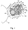
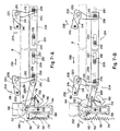
- the illustrated developing device comprises a main body 6 including a supporting section 2 and a developing section 4 extending from the supporting section 2 (see Figures 2 and 4 also).
- the main body 6 of the developing device is detachably mounted on an image-forming machine such as an electrostatic copying machine.
- the developing section 4 of the main body 6 is free to pivot between a non-operating position shown by a sold line in Figure 1 and an operating position shown by a two-dot chain line in Figure 1.
- the developing section 4 is provided with a development housing 8 defining a developing chamber 10.
- An opening 11 is formed in the left surface of the development housing 8 in Figure 1 (that surface which faces a photosensitive material to be described).
- a magnetic brush mechanism 12 constituting applicator means is disposed in the left part of the developing chamber 10, and agitating means 14 is disposed in the right part of the developing chamber 10.
- the magnetic brush mechanism 12 is comprised of a combination of a hollow sleeve member 18 to be rotated in the direction shown by an arrow 16 and a stationary permanent magnet 20 disposed within the sleeve member 18, and a developer is held on the peripheral surface of the hollow sleeve member 18 and carried in the direction of arrow 16.
- the agitating means 14 comprises a supporting shaft 22 and an agitating member 24 mounted on the supporting shaft 22, and outwardly projecting vanes 26 are provided on the peripheral surface of the agitating member 24.
- the agitating means 14 is rotated in the direction shown by an arrow 28 to agitate and mix the developer in the developing chamber 10 and triboelectrically charge the toner in the developer.
- a guide member 30 is provided above the hollow sleeve member 18 and the agitating member 24.
- a toner transfer chamber 32 is defined in the upper part of the developing chamber 10 (in other words, above the guide member 30), and toner transfer means 34 is disposed in the toner transfer chamber 32.
- a toner supply opening 36 is formed in the bottom of the toner transfer chamber 32.
- the toner supplied from a toner cartridge (to be described hereinafter) is transferred in a direction perpendicular to the sheet surface in Figure 1 by the action of the toner transfer means 34.
- the transferred toner is supplied onto the guide member 30 through the toner supply opening 36, and allowed to flow down onto the agitating member 24 along the upper surface of the guide member 30.
- the agitating member 24 mixes the developer flowing down from the guide member 30 (containing the fresh toner supplied as stated above) and the developer present in the developing chamber 10, and feeds the mixture to the magnetic brush mechanism 12.
- the magnetic brush mechanism 12 magnetically holds the resulting mixed developer onto the peripheral surface of the hollow sleeve member 18 and transfers it in the direction of arrow 16.
- a brush length adjusting portion 38 projecting toward the peripheral surface of the sleeve member 18 is provided as a one-piece unit with part of the development housing 8. Hence, the excess of the developer held on the hollow sleeve member 18 is removed from it by the action of the brush length adjusting portion 38. The removed developer is conducted upwardly and then allowed to flow down toward the agitating member 24 over the upper surface of the guide member 30.
- a toner concentration detector 40 is disposed in proximity to the brush length adjusting portion 38. The toner concentration detector 40 detects the toner concentration of the developer which has been removed from the hollow sleeve member 18 and conducted upwardly.
- the developer whose brush length has been adjusted by the action of the brush length adjusting portion 38 is further transferred in the direction of arrow 16 by the rotation of the hollow sleeve member 18 and acts on the surface of image-bearing means such as a rotating drum 42 having a photosensitive material disposed on its peripheral surface.
- a latent electrostatic image is formed on the surface of the photosensitive material on the rotating drum 42 by means known per se .
- the latent electrostatic image is developed to a toner image.
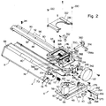
- the supporting section 2 exists at one end portion (the right bottom portion in Figures 2 and 4, and the left end portion in Figure 5), and the developing section 4 extends from the supporting section 2 to the other end portion (to the left top in Figure 2, and to the right in Figure 4).
- the supporting section 2 has a supporting main body 46, and a gripping member 48 is provided as a one-piece unit with the front surface of the supporting main body 46.
- a pair of protruding portions 50 spaced from each other in the left-right direction are provided in the rear surface of the supporting main body 46, and a cylindrical receiving depressed portion 52 ( Figures 4 and 5)is defined in each protruding portion 50.
- a supporting wall 54 extending substantially perpendicularly and upwardly is provided in the supporting main body 46.
- a connecting terminal 56 constituting electrical connecting means is mounted on the supporting wall 54.
- An engaging member 60 having a claw portion 58 is pivotably mounted on the supporting main body 46, and a biasing spring 62 is attached to the engaging member 60. By depressing an operating portion 64 of the engaging member 60, the engaging member 60 can be pivoted against the biasing force of the biasing spring 62.
- the development housing 8 of the developing section 4 has a pair of end walls 66 and 68 spaced from each other in the width direction of the housing 8, i.e. the front-rear direction of the image-forming machine (a direction perpendicular to the sheet surface in Figure 1, a direction from right bottom to left top in Figure 2, and the left-right direction in Figure 5) and a bottom wall 70, a side wall 72 and an upper wall 74 ( Figure 1) disposed between the end walls 66 and 68, and these walls 66, 68, 79, 72 and 74 define the developing chamber 10.
- shaft portions (not shown) provided at opposite end portions of the hollow sleeve member 18 in the magnetic brush mechanism 12 are supported rotatably on the end walls 66 and 68, and supported on the end wall 66 via a supporting member 76 mounted on the end wall 66.
- one end of a wire 78 for applying a development bias voltage to the hollow sleeve member 18 is connected to the supporting member 76 by means of a screw member 79.
- the other end of the wire 78 is connected to the connecting terminal 56 of the supporting section 2.
- the supporting shaft 22 of the agitating means 14 is also rotatably supported on the end walls 66 and 68.
- an auxiliary housing 80 is mounted on the upper wall 74 of the development housing 8, and the auxiliary housing 80 is provided with a cartridge loading portion 82 and a toner transfer portion 84.
- the cartridge loading portion 82 defines a toner discharge chamber 86, and its upper surface is opened.
- a toner cartridge 88 ( Figure 10) is detachably loaded above the toner discharge chamber 86, and the toner in the toner cartridge 88 is discharged into the toner discharge chamber 86.
- the toner cartridge 88 and the cartridge loading portion 82 will be described hereinafter in detail.
- the toner transfer portion 84 is constructed of a hollow cylindrical wall 90 and extends from the cartridge mounting portion 82 to the left top in Figure 2.
- a pair of protrusions 92 are provided opposite to the peripheral surface of the cylindrical wall 90, and the auxiliary housing 80 is mounted in position on the development housing 8 by securing the protrusions 92 to the upper wall 74 of the housing 8 by screws 94.
- the toner transfer chamber 32 defined by the cylindrical wall 90 is allowed to communicate with the toner discharge chamber 86, and the toner supply opening 36 formed at its bottom has a progressively increasing width in the toner transfer direction shown by an arrow 96.
- a helical member 98 constituting the toner transfer means 34 is rotatably mounted in the toner transfer chamber 32.
- One end portion of the helical member 98 extends from the toner transfer chamber 32 to the toner discharge chamber 86, and its other end portion extends to the left top in Figure 2 in the developing chamber 10. Accordingly, the toner discharged into the toner discharge chamber 86 from the toner cartridge 88 ( Figure 10) is transferred in the direction of arrow 86 in the toner transfer chamber 32 by the action of the helical member 98.
- the width of the toner supply opening 36 is relatively small.
- the proportion of the toner supplied through the toner supply opening 36 is relatively small.
- the width of the toner supply opening 36 is relatively large in the downstream portion of the toner transfer chamber 32 in the transfer direction shown by arrow 96, the proportion of the toner supplied through the toner supply opening 36 is relatively large in spite of the relatively small amount of the toner transferred. Hence, the toner from the toner discharge chamber 86 is supplied substantially uniformly over the entire width direction of the developing chamber 10 through the toner supply opening 36.
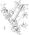
- the supporting section 2 and the developing section 4 are connected as described below. Mainly with reference to Figures 2 and 4, a circular hole 100 and an arcuate guide hole 102 are formed in the supporting wall 54 in the supporting section 2. On the other hand, in the developing section 4, a supporting shaft portion 104 and a guide shaft portion 106 to be guided are provided on the outside of the end wall 66.
- the developing section 4 is attached to the supporting section 2 by inserting the supporting shaft portion 104 into the hole 100 and the guide shaft portion 106 into the guide hole 102.
- the supporting shaft portion 104 and the guide shaft portion 106 slightly project through the supporting wall 54 of the supporting section 2, and a linking plate piece 110 is attached to the end surfaces of the supporting shaft portion 104 and the guide shaft portion 106 by screws 108.
- a biassing coil spring 112 (constituting biasing means) is fitted over the supporting shaft portion 104. One end portion of the biasing coil spring 112 is anchored at part of the supporting wall 54, and the other end portion is anchored at the guide shaft portion 106. The biasing coil spring 112 elastically biases the developing section 4 in the direction shown by an arrow 114 (see Figure 1) toward the operating position shown by the two-dot chain line in Figure 1.
- the main body of the image-forming machine such as the main body of an electrostatic copying machine has a front base plate 116 and a rear base plate 118 ( Figure 5) spaced from each other in the front-rear direction (the left-right direction in Figure 5).
- An opening 117 ( Figure 4) having a shape nearly corresponding to the shape of the developing section 4 of the developing device 6 is formed in the front base plate 116, and the developing section 4 is positioned in the required manner between the front base plate 116 and the rear base plate 118 as shown in Figure 5 through the opening 117.
- a plate-like supporting guide member 284 having a shape corresponding to the shape of the lower portion of the developing section 4 is provided at a site which defines the lower edge of the opening 117.
- the supporting guide member 284 projects slightly ourwardly from the front base plate 116, and its other end portion projects slightly inwardly from the front base plate 116.
- the supporting guide member 284 has a predetermined width in the front-rear direction (see Figures 9-A and 9-B).
- the supporting guide member 284 guides and supports the developing section 4 at the time of mounting and detaching the main body 6 of the developing device.
- a pair of supporting pins 120 ( Figure 4) spaced from each other in the left-right direction are implanted.
- the pair of supporting pins 120 are disposed corresponding to the pair of receiving depressed portions 52 defined in the supporting section 2.
- a connecting terminal 119 (constituting electrical connecting means) corresponding to the connecting terminal 56 of the supporting section 2 is provided in the front surface of the front base plate 116.
- the hollow sleeve member 18 and the toner concentration detector 40 are connected to a bias power supply and control means (both of which are not shown) provided in the main body of the image-forming machine via the connecting terminals 56 and 119.
- the connecting terminal 56 may be of a convex shape, for example, and the other connecting terminal 119 may be of a concave shape conforming to the convex shape.
- a sleeve 121 ( Figure 5) made of a metalic material is fitted in the inside of one protruding portion 50 (the one on the right top in Figures 2 and 3).
- the front base plate 116 and the supporting pins 120 are also formed of a metallic material.
- a grounding wire 124 of an electric motor 122 is fixed to the above one protruding portion 50 in order to rotate the helical member 98, and connected to a sleeve member 121 via a fixing screw.
- the grounding wire 124 of the electric motor 122 is ground to the front base plate 116 via the fixing screw, the sleeve member 112 and the supporting pin 120.
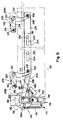
- a supporting plate 126 extending in the front-rear direction is disposed between the front base plate 116 and the rear base plate 118.
- An upwardly opened channel-like guide portion 128 is provided in the upper end portion of the supporting plate 126, and extends in a straight line from one end of the supporting plate 126 toward its rear end portion.
- a greater portion of the guide portion 128 extends substantially horizontally, and only its other end portion 128a is inclined downwardly toward the other end (the right end in Figure 5).
- the upper part of the right end (in Figure 1) of the development housing 8 has provided therein a rightwardly projecting protruding portion 130 to be supported, and a downwardly projecting piece 132 is formed integrally in the under surface of the protruding portion 130.
- a protruding portion 134 is formed in the outside surface of the end wall 68 of the developing section 4, and a shaft member 136 is mounted on the rear base plate 118.
- a receiving depressed portion 140 extending to the left in Figure 5 is defined in the end surface of the protruding portion 134.
- a fixing portion 142 is provided in one end portion of the shaft member 136, and the other end portion of the shaft member 136 projects inwardly through the rear base plate 118.
- a gear 144 is attached to this projecting portion of the shaft member 136 so as to be movable in the front-rear direction shown by an arrow 138.
- the other end of the shaft member 136 projects inwardly from the gear 144.
- a biasing spring member 146 for elastically biasing the gear 144 inwardly.
- the gear 144 is drivingly connected to a driving source for the image-forming machine although it is not shown in the accompanying drawings.
- the protruding piece 132 provided in the development housing 8 is guided by the guide portion 128 of the supporting plate 126 and moved in the mounting direction shown by an arrow 148.
- the projecting end portion of the shaft member 136 is positioned in the receiving depressed portion 140 of the protruding portion 134 provided in the end wall 68 of the developing section 4.
- one end portion of the developing section 4 is rotatably supported by the supporting portion 2 via the supporting shaft portion 104, and the other end portion of the developing section 4 is rotatably supported on the rear base plate 118 via the shaft member 136.
- the developing section 4 is thus free to rotate between the aforesaid non-operating and operating positions about the supporting shaft portion 104 and the shaft member 136 as a center (more specifically about a central axis of the supporting shaft portion 104 and the shaft member 136 which constitutes a rotating central axis extending in the widthwise direction of the main body 6 of the developing device).
- a gear for rotating the hollow sleeve member 18 of the magnetic brush mechanism 12 and a gear for rotating the supporting shaft 24 of the agitating means 14 are drivingly connected to the gear 144 although these non-numbered gears are not shown in the drawings.
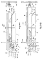
- a changeover mechanism 150 is provided which selectively brings the developing section 4 to the non-operating position shown by the solid line in Figure 1 and the operating position shown by the two-dot chain line in Figure 1 when the main body 6 of the developing device is set on the main body of the image-forming machine.
- the illustrated changeover mechanism 150 is provided with cam means 152 and an elevating-lowering member 154 adapted to be elevated or lowered by the action of the cam means 152.
- the elevating-lowering member 154 has a main body portion 156, an acting portion 158 provided in an intermediate portion in the main body portion 156, a bent portion 160 at the upper end of the main body portion 156, and a cam follower portion 162 extending downwardly from the bent portion 160.
- a vertically extending elongate hole 164 is formed in the main body portion 156.
- the elevating-lowering member 154 is mounted vertically movably on the other end portion of the supporting frame 126 in the manner mentioned below.
- a guide member 166 is disposed in the hole 164 of the main body portion 156 of the elevating-lowering member 154 (more specifically, a guide projecting portion 166a of the guide member 166 is positioned in the hole 164).
- mounting pins 170 spaced from each other in the vertical direction are provided in a mounting member 168.
- the elevating-lowering member 154 is mounted on the guide member 166 attached to the supporting plate 126.
- a fixing screw 176 is threadedly secured to the supporting plate 126 through the mounting member 168 and the guide member 166.
- the elevating-lowering member 154 is free to move between an elevated position (the position shown in Figure 7-B) at which the lower end of the hole 164 abuts against the lower end of the guide protruding portion 166a and a lowered position (the position shown in Figures 6 and 7-A) at which the upper end of the hole 164 abuts against the upper end of the guide protruding portion 166a).
- the acting portion 158 of the elevating-lowering member 154 is constructed such that it can act on the protruding portion 132 provided in the development housing 8.
- a biasing spring 178 is also attached to the elevating-lowering member 154.
- biasing spring 178 One end portion of the biasing spring 178 is engaged with an engaging protruding piece 156a provided in the main body portion 156 of the elevating-lowering member 154 and its other end portion is engaged with an engaging piece 179 provided in the lower end portion of the supporting plate 126.
- the biasing spring 178 elastically biases the elevating-lowering member 154 downwardly toward the aforesaid lowered position.
- the illustrated cam means 152 is provided with a fan-like first cam 180 and a circular second cam 182.
- an auxiliary plate 186 is secured to the rear end portion of the upper part of the supporting plate 126 by means of a fixing screw 184.
- An electric motor 188 is mounted on the auxiliary plate 186, and the first cam 180 and the second cam 182 are mounted on an output shaft 190 which projects from the electric motor 188 through the auxiliary plate 186.
- the first cam 180 and the second cam 182 are formed as a one-piece unit.
- the first cam 180 is disposed so that its peripheral surface acts on the lower edge of the cam follower portion 162 of the elevating-lowering member 154, and the second cam 182 is disposed so as to be positioned between the main body portion 156 and the cam follower portion 162 of the elevating-lowering member 154.
- Switch means 192 such as a microswitch is attached to the second cam 182.
- the switch means 192 has a detecting arm 192a, and is adapted to be on when the large-diameter portion 194 of the second cam 182 acts on the detecting arm 192a and to be off when the small-diameter portion 196 of the second cam 182 acts on the detecting arm 192a (or does not substantially act on the detecting arm 192a).
- the first cam 180 is held at a second angular position displaced substantially by an angle of 180 degrees from a first angular position.
- the small-diameter portion 200 of the first cam 180 acts on the lower edge of the cam follower portion 162 of the elevating-lowering member 154 and the elevating-lowering member 154 is moved to the lowered position by the action of the biasing spring 178.
- the magnetic brush mechanism 12 When the developing section 4 is thus held at the operating position, the magnetic brush mechanism 12 is positioned in proximity to the peripheral surface of the rotating drum 42 and the developer held on the hollow sleeve member 18 acts on the surface of the photosensitive material on the rotating drum 42 in the developing zone 44. As a result, a latent electrostatic image formed on the surface of the photosensitive material is developed to a toner image.
- the acting portion 158 As shown in Figure 7-A, when the elevating-lowering member 154 is held at the lowered position, the acting portion 158 abuts aginst, or is away downwardly from, the under surface of the protruding piece 132 of the development housing 8. Therefore, the acting portion 158 does not substantially act on the protruding piece 132.
- the electric motor 188 is rotated in the direction of arrow 198, and with it, the first cam 180 and the second cam 182 are rotated.
- the small-diameter portion 196 of the second cam 182 acts on the detecting arm 192a of the switch means 192, the electric motor 188 is deenergized on the basis of a detection signal from the switch means 192, and the elevating-lowering member 154 and elements relating to it are held in the state shown in Figure 7-B.
- the first cam 180 is held at the first angular position by being substantially moved away from the second angular position.
- the large-diameter portion 202 of the first cam 180 acts on the lower edge of the cam follower portion 162 of the elevating-lowering member 154, the elevating-lowering member 154 is held at the elevated position against the action of the biasing spring 178.
- the acting portion 158 of the elevating-lowering member 154 acts on the protruding piece 132 of the development housing 8 to elevate it as shown in Figures 1 and 7-B. Consequently, the developing section 4 is turned in a direction opposite to the direction of arrow 114 and brought to the non-operating position shown by a solid line in Figure 1.
- the magnetic brush mechanism 12 is positioned apart from the peripheral surface of the rotating drum 42, and the developer held on the hollow sleeve member 18 does not substantially act on the surface of the photosensitive material on the rotating drum 42.
- the illustrated developing device is provided with positioning means for holding the developing section 4 of its main body 6 exactly at the aforesaid operating position.
- the illustrated positioning means 204 is equipped with a pair of pressing members 206 spaced from each other in the widthwise direction of the main body 6 of the developing device (the direction from right bottom to left top in Figure 3, and the left-right direction in Figure 6).
- an upwardly extending projecting portion 208a is provided at one end portion of the supporting plate 126, and one pressing member 206 is pivotably mounted on a pin 210 implanted in the projecting portion 208a.
- An upwardly extending projecting portion 208b is provided at the other end portion of the supporting plate 126, and the other pressing member 206 is pivotably mounted on a pin 210 implanted in the projecting portion 208b.
- An engaging member 211 for preventing detachment of the press member 206 is attached to the end of each pin 210.
- Each of the press members 206 is nearly in an inverted L-shape, and has a downwardly extending arm portion 212 and a pressing arm portion 214 extending to the left in Figures 3 and 6.
- a nearly triangular pressing block piece 216 is attached to the end of the pressing arm portion 214 by means of a fixing screw 218.
- Each of the pressng members 206 is free to pivot between a first position shown in Figures 6 and 7-A and a second position shown in Figure 7-B.
- a biasing coil spring 220 constituting elastic biasing means is attached to each of the pressing members 206.
- the biasing coil spring 220 is fitted over the pin 210 and its one end portion is engaged with a hole 222 ( Figure 3) formed in the supporting plate 126. Its other end portion is engaged with the pressing arm portion 214 of the pressing member 206.
- the biasing coil spring 220 elastically biases each pressing member 206 toward the aforesaid first position, namely counterclockwise in Figures 3 and 6.
- the illustrated positioning means 204 is further equipped with a moving member 224 for pivoting the pressing members 206.
- the moving member 224 has a relatively long first member 226 and a relatively short second member 228, and the first member 226 is mounted on the supporting plate 126 so that it can move in the widthwise direction of the main body 6 of the developing device.
- a pair of supporting screws 230 spaced from each other in the widthwise direction of the main body 6 of the developing device are threadedly secured to the supporting plate 126, and a sleeve member 232 is rotatably mounted on each of the supporting screws 230.
- a pair of elongate holes 234 are formed in the opposite end portions of the first member 226 corresponding to the pair of supporting screws 230.
- the first member 226 is mounted on the supporting plate 126.
- the first member 226 is free to move between a position at which each supporting screw 230 is positioned at one end portion of each elongate hole 234 and a position at which each supporting screw 230 is positioned at the other end portion of each elongate hole 234.
- Acting sleeve members 236 are mounted on the opposite end portions of the first member 226 corresponding to the pressing members 206.
- supporting screws 238 are threadedly secured to both end portions of the first member 226, and the acting sleeve members 236 are rotatably mounted on the supporting screws 238.
- the pressing members 206 are reliably prevented from turning counterclockwise in Figures 6, 7-A and 7-B.
- long holes 240 for the acting sleeve members 236 are formed in the supporting plate 126.
- a large-diameter portion 240a for permitting insertion of each acting sleeve member 236 is formed in one end of each long hole 240 in the supporting plate 126.
- the second member 228 is interposed between the cam means 152 and the first member 226.
- One end portion of the second member 228 is rotatably connected to the first member 226 via a connecting screw 242 threadedly secured to the left end of the first member 226 in Figures 3 and 6 and a sleeve member 244 attached to the connecting screw 242.
- a disc-like portion 246 is integrally formed in the second cam 182, and the other end portion of the second member 228 is rotatably connected to the second cam 182 via a connecting screw 248 threadedly secured to the disc-like portion 246 in eccentric relationship and a sleeve member 250 attached to the connecting screw 248.
- the positioning means 204 is held in an operating state shown in Figure 7-A when the first cam 180 is at the second angular position.
- the connecting screw 248 secured to the second cam 182 is positioned in proximity to the first member 226 and therefore, the first member 226 is moved in the direction shown by an arrow 252 ( Figure 7-A) via the second member 228 and held at the position shown in Figure 7-A (the position at which the supporting screw 230 is positioned at one end portion of the long hole 234 of the first member 226).
- the supporting screws 238 are also moved to permit pivoting of the pressing members 206 in the direction shown by an arrow 254 ( Figure 7-A).
- the pressing members 206 are pivoted in the direction of arrow 254 by the action of the biasing coil springs 220. Consequently, as shown in Figure 7-A, the pressing block piece 216 provided in the pressing arm portion 214 of each pressing member 206 acts on the upper surface of the right end portion of the developing section 4 in Figure 1 (more specifically the upper surface of one protrusion 92 (the right protrusion in Figures 1 and 3) provided in the auxiliary housing 80). As a result, the developing section 4 is turned in the direction of arrow 114 ( Figure 1) by its one weight and by the biasing force of the biasing coil spring 112 and surely held at the operating position.
- each of the pressing members 206 is elastically biased in the direction of arrow 254 ( Figure 7-A) by the action of the biasing coil spring 220, the developing section 4 is elastically held exactly at the operating position by the action of the biasing coil springs 220 and the pressing members 206 (and therefore, the pressing members 206 are held elastically at the first position).
- the positioning means 204 is held in a non-operating state shown in Figure 7-B.
- the connecting screw 248 secured to the second cam 182 is positioned away from the first member 226, and therefore, the first member 226 is moved in the direction of arrow 256 ( Figure 7-B) via the second member 228 and held at the position shown in Figure 7-B (the position at which the supporting screw 230 is held at the other end portion of the long hole 234 of the first member 226).
- the supporting screws 238 are moved with the movement of the first member 226, and the supporting screws 230 act on the arm portions 212 of the pressing members 206 via the acting sleeve members 236 to pivot the arm portions 212 in the direction shown by an arrow 258 ( Figure 7-B).
- the pressing members 206 are held at the second position shown in Figure 7-B.
- the developing section 4 is held at the non-operating position. Furthermore, since the pressing members 206 are held at the second position, the pressing block pieces 216 abut against, or positioned slightly upwardly from, the developing section 4. Hence, the pressing members 206 do not substantially act on the developing section 4, and the developing section 4 is exactly held at the non-operating position by the action of the elevating-lowering member 154.
- the above embodiment is preferably constructed such that the elevating-lowering member 154 is elevated by the first cam 180 after the pressing by the pressing members 206 is cancelled by moving the first member 226 in the direction of arrow 256.
- the above developing device has the following features in relation to the positioning means 204.
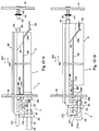
- the pressing members 206 of the positioning means 204 are held at the second position, and the acting portion 158 of the elevating-lowering member 154 is held on the same level as the guide portion 128 of the supporting plate 126. Accordingly, the main body 6 of the developing device can be detached from the main body of the image-forming machine by moving it in the detaching direction shown by arrow 260 ( Figure 5). At the time of detaching, the protruding piece 132 provided in the development housing 8 is moved while being guided by the guide portion 128 of the supporting plate 126 and the acting portion 158 of the elevating-lowering member 154 at the elevated position.
- the developing section 4 is therefore kept at the non-operating position during detachment, and the developer held by the magnetic brush mechanism 12 does not substantially act on the surface of the photosensitive material on the rotating drum 42. Damage of the photosensitive material during detachment can therefore be prevented. At the same time, scattering of the developer which occurs upon its acting on the photosensitlve material can be reliably prevented. Furthermore, the pressing members 206 are held at the second position and do not substantially act on the developing section 4. Moreover, since the acting portion 158 and the guide portion 128 are maintained on the same level, the main body 6 of the developing device can be easily moved in the detaching direction shown by arrow 260. For the detachment of the main body 6 of the developing device in the aforesaid state, see Figures 9-A and 9-B also.
- the acting position 158 of the elevating-lowering member 154 is substantially on the same level as the lower end of the other end portion 128a of the guide portion 128 provided in the supporting plate 126 (see Figures 7-A, 8-B and 8-C).
- the developing section 4 is reliably held at the opening position as a result of the positioning means 204 being held in the operating state.
- the pressing members 206 are biased toward the first position by the biasing coil springs 220, but can be pivoted to the second position against the biasing action of the biasing coil springs 220.
- the main body 6 of the developing device can be detached from the main body of the image-forming machine even when the elevating-lowering member 154 is at the lowered position.
- the protruding piece 132 provided in the development housing 8 first moves inclinedly upwardly by the guidance of the inclined surface of the other end portion 128a of the guide portion 128 in the supporting plate 126. Thereafter, the protruding piece 132 is guided by a substantially horizontal part of the guide portion 128 ( Figure 8-C).
- the main body 6 of the developing device can be detached in the required manner from the main body of the image-forming machine by moving it in the detaching direction shown by arrow 260.
- the developing section 4 is held at the non-operating position by the action of the inclined other end portion 128a of the guide portion 128 and the protruding piece 132 provided in the development housing 8.
- the developing section 4 is moved while being held at the non-operating position.
- the protruding piece 132 in the development housing 8 is preferably constructed as to be substantially astride the substantially horizontal part of the guide portion 128 and the acting portion 148 of the elevating-lowering member 154. This arrangement permits easier mounting and detachment of the main body 6 of the developing device.
- the illustrated developing device is further provided with means for holding the developing section 4 at a non-operating position.
- the non-operating position holding means 262 has a holding member 264 movable in the mounting and detaching directions of the main body 6 of the developing device.
- the holding member 264 has a main body portion 266 extending in the mounting direction shown by the arrow 148 ( Figure 5), a suspending piece 268 provided in the right end portion in Figure 5 of the main body portion 266 (the front end portion in the mounting direction of arrow 148) and a turn hampering portion 270 provided in the left end portion in Figure 5 of the main body portion 266 (the rear end portion in the mounting direction of arrow 148).
- a guide groove 274 ( Figure 2) having a nearly T-shaped vertical sectional shape is provided in a protruding portion 272 extending outwardly from the end wall 66 of the development housing 8.
- the main body portion 266 of the holding member 264 is fitted in the guide groove 274 so as to be free to move in the directions shown by arrows 148 and 260.
- the suspending piece 268 and the turn hampering portion 270 of the holding member 264 project downwardly through downwardly extending opening formed in the guide groove 274, as shown in Figure 5.
- the turn hampering portion 270 of the holding member 264 is constructed such that it engages part of the supporting section 2 when it is at an engaging position shown in Figures 9-A and 10-A.
- the under surface of the turn hampering portion 270 defines a substantially horizontal hampering surface 270a
- the upper surface of part of the supporting main body 46 in the supporting section 2 defines a substantially horizontal engaging surface 276 adapted to cooperate with the hampering surface 270a.
- the hampering surface 270a of the turn hampering portion 270 comes into engagement with the engaging surface 276 of the supporting section 2.
- biasing means is attached to the holding member 264.
- the biasing means is constructed of a biasing spring 278.
- a hampering member 282 is provided in the development housing 8. The hampering member 282 abuts against the suspending piece 268 of the holding member 264 and reliably hampers the movement of the holding member 264 beyond the engaging position.
- the holding member 264 is usually held at the engaging position when its main body 6 is detached from the image-forming machine.
- the suspending piece 268 of the holding member 264 abuts against the hampering member 282 provided in the development housing 8, and the hampering surface 270a of the turn hampering member 270 is kept in engagement with the engaging surface 276 defined in the supporting main body 46 of the supporting section 2.
- the protruding piece 132 provided in the development housing 8 be positioned at a substantially horizontally extending part of the guide portion 128, and the holding member 264 be held at the engaging position.
- the pair of supporting pins 120 can easily be inserted into the receiving depressed portions 52 of the supporting section 2.
- the holding member 264 With the movement of the main body 6 in the direction of arrow 148, the holding member 264 is moved in the direction of arrow 260 relative to the developing section 4 against the biasing force of the biasing spring 278. As a result, the engagement between the hampering surface 270a of the holding member 264 and the engaging surface 276 of the supporting section 2 is cancelled, and the developing section 4 is permitted to turn toward the operating position.
- the protruding piece 132 of the development housing 8 is positioned at the substantially horizontal part of the guide member 128 and by moving the main body 6 of the developing device further slightly in the direction of arrow 148, the lower end of the protruding piece 132 moves away from the substantially horizontal part of the guide portion 128.
- the front end portion of the shaft member 136 mounted on the rear base plate 118 is received in the receiving depressed portion 140 formed in the protruding portion 134 provided in the end wall 68 ( Figure 2) of the development housing 8, and the main body 6 is detachably mounted on the main body of the image-forming machine.
- one end portion of the main body 6 of the developing device is supported by the front base plate 116 as a result of the supporting pin 120 being positioned in the receiving depressed portion 52, and the other end portion of the main body 6 is supported by the rear base plate 118 as a result of the front end portion of the shaft member 136 being positioned within the receiving depressed portion 140.
- the protruding piece 132 in the development housing 8 is positioned above the acting portion 158 of the elevating-lowering member 154 substantially away from the substantially horizontal part of the guide portion 128.
- the claw portion 58 of the engaging member 60 mounted on the supporting section 2 engages part of the front base plate 116, and the movement of the main body 6 of the developing device in the detaching direction of arrow 280 is hampered.
- the acting portion 158 of the elevating-lowering member 154 is on the same level as the substantially horizontal part of the guide portion 128 as shown in Figures 10-A and 10-B. Accordingly, when the main body 6 of the developing device is mounted in position, the developing section 4 is kept at the non-operating position by the action of the acting portion 158. Thus, to bring the developing section 4 to the operating position, the elevating-lowering member 154 should be held at the lowered position. On the other hand, when the elevating-lowering member 154 is at the lowered position, the acting portion 158 of the elevating-lowering member 154 is substantially on the same level as the lower end of the inclined other end portion 128a of the guide member 128.
- the protruding piece 132 of the development housing 8 is moved downwardly along the other end portion 128a of the guide portion 128 just prior to mounting the main body 6 in position.
- the developing section 4 is held at the operating position.
- the developing device further has the following feature.
- the developing section 4 is held at the non-operating position when the main body 6 of the developing device is to be mounted in position or more specifically the protruding piece 132 moves the substantially horizontal part of the guide portion 128 while the elevating-lowering member 154 is at the elevated or lowered position. Accordingly, the developer held on the magnetic brush mechanism 12 does not substantially act on the photosensitive material provided on the rotating drum 42, and damage of the photosensitive material during mounting of the developing device 6 can be reliably prevented.
- the holding member 264 when the main body 6 of the developing device is detached from the main body of the image-forming machine, the holding member 264 is held at the engaging position in the manner to be described below.
- the holding member 264 is moved in the direction of arrow 148 relative to the development housing 8 by the action of the biasing spring 278.
- the holding member 264 abuts against the hampering member 282 provided in the development housing 8 and is thus held at the engaging position as shown in Figure 9-A or 10-A. Accordingly, even when the main body 6 of the developing device is detached from the main body of the image-forming machine, the holding member 264 is held at the engaging position and the developing section 4 continues to be held at the non-operating position.
- the pair of supporting pins 120 get out of the receiving depressed portions 52 of the supporting section 2. In the illustrated embodiment, after one connecting terminal 56 mounted on the supporting section gets out of the other connecting terminal 119 mounted on the front base plate 116, the supporting pins 120 come out of the receiving depressed portions 52.
- the illustrated toner cartridge 88 has a square-columnar main body 288.
- the main body 288 has an upper wall 290 having a toner supply opening 292 ( Figures 14-A to 14-C) defined therein. After filling toner, the toner supply opening 292 is closed by a closure 294.
- the lower end portion of the main body 288 is funnel-shaped and a toner discharge opening 296 ( Figures 14-A to 14-C) is defined at its lower end.
- a rectangular flange 298 is integrally provided at the lower end (the opening part of the toner discharge opening 296) of the main body 288.
- the toner discharge opening 296 of the main body 288 is substantially sealed up.
- its one end portion is bent upwardly and bonded to the upper surface of the flange 298. Accordingly, the sheet material 300 can be easily stripped from the flange 298 by removing its one end portion bonded to the upper surface of the flange 298 and pulling it in the direction shown by an arrow 302.
- the toner cartridge 88 further includes a cover member 304 for closing the toner discharge opening 296 at the time of detaching the main body 288 of the toner cartridge from the main body 6 of the developing device.
- the illustrated cover member 304 is nearly rectangular corresponding to the shape of the flange 298 and depressed portions 306 for receiving the two side end portions of the flange 298 are defined at both side ends of the cover member 304.
- the toner discharge opening 296 of the main body 288 can be closed by positioning the two side end portions of the flange 298 in the depressed portions 306 of the cover member 304 and moving the cover member 304 relatively in the direction shown by an arrow 308 ( Figure 14-B) as shown in Figure 14-C.
- a stop piece 310 for reliably hampering the movement of the cover member 304 in the direction of arrow 308 when the cover member 304 has been mounted in position on the flange 298 is preferably provided in the cover member 304.
- the toner cartridge is constructed such that the cover member 304 cannot be substantially moved in the detaching direction when it has been mounted on the flange 298 of the main body 288 of the toner cartridge.
- detaching movement hampering means 312 is provided in the flange 298 and the cover member 304.
- the illustrated detaching movement hampering member 312 is comprised of a combination of a hole 314 (constituting a depressed portion) formed in the flange 298 and an engaging projecting portion 316 formed in the cover member 304.
- the engaging projecting portion 316 is inclined downwardly in the mounting direction of arrow 308 at its forward part in the mounting direction, but substantially projects vertically at its rear end in the mounting direction. Hence, when the cover member 304 is moved in the direction of arrow 308, the hole 314 and the engaging projecting portion 316 are engaged with each other by the elastic deformation of the flange 298 and the engaging projecting portion 316. After the hole 314 and the engaging projecting portion 316 have come into engagement, it is substantially impossible to move the engaging projecting portion 316 and therefore, the cover member 304, in a direction opposite to the direction mentioned above. If desired, it is possible to provide the engaging protruding portion in the flange 298 and the receiving depressed portion in the cover member 304 contrary to the above embodiment.
- the cover member 304 is constructed such that when it is not used, it is detachably mounted on one side wall 318 (the rear side wall as viewed in the mounting direction of the cartridge main body 288 shown by an arrow 320 in Figure 14-A) of the main body 288 of the toner cartridge.
- a pair of L-shaped supporting protrusions 322 spaced from each other are provided in the side wall 318 of the main body 288.
- Each of the supporting protrusions 322 extends vertically and has a projecting portion adapted to be positioned in the depressed portion 306 of the cover member 304.
- a stop piece 324 is provided in the lower end portion of the side wall 318.
- the cover member 304 is detachably mounted on the side wall 318 of the main body 288 by positioning the projecting portions of the supporting protrusions 322 in the depressed portion 306 of the cover member 304 and moving the cover member 304 downwardly.
- the lower edge of the cover member 304 in Figure 14-A abuts against the stop piece 324 and is held in the state shown in Figure 14-A.
- the upper end portion of the cover member 304 projects slightly upwardly from the upper wall 290 of the main body 288 of the toner cartridge. By holding the projecting upper end portion and moving it upwardly, the cover member 304 can be easily detached from the side wall 318.
- the cover member 304 may be adapted to be mounted on the flange 298 of the main body 288 instead of the side wall 318 and, in this arrangement, it is necessary to store the cover member 304 when the cartridge 88 is in use. (Furthermore, in this arrangement, to prevent substantial engagement between the hole 314 of the flange 298 and the engaging projecting portion 316 of the cover member 304, it is necessary to cover the hole 314 substantially by applying the sheet material 300 to at least the under surface of the flange 298).
- the cartridge loading portion 82 of the main body 6 of the developing device into which the cartridge main body 288 is loaded detachably has four side walls and is nearly cylindrical, and a nearly rectangular flange 326 is provided at its upper end.
- a seal member 328 such as a sponge, capable of being elastically deformed is bonded to the inner circumferential part of the flange 326.
- a guide cover 332 is attached to the outer circumferential part of the flange 326 by means of a securing screw 330.
- the guide cover 332 define a pair of guide grooves 334 extending in the loading direction of the cartridge main body 288 in cooperation with the flange 326 at both side portions.
- a nearly semicircular opening 336 opened at one end (on the loading side of the main body 288).
- a rotating shaft 340 is rotatably mounted on one side wall 338 (the side wall located at right bottom in Figure 2) of the cartridge loading portion 82.
- One end portion of the rotating shaft 340 projects outwardly through the side wall 338, and this projecting end portion is drivingly connected to an output shaft 342 of the electric motor 122.
- a receiving depressed portion 344 is provided in one end portion of the rotating shaft 340 and an engaging pin 346 is provided in the output shaft 342.
- the rotating shaft 340 is drivingly connected to the output shaft 342.
- the other end portion of the rotating shaft 340 projects inwardly through the side wall 338 and the helical member 98 of the toner transfer means 34 is connected to this inwardly projecting end portion of the rotating shaft 340 (see Figures 13-A and 13-B).
- discharge facilitating means 348 is provided in order to increase the dischargeability of the toner in the cartridge main body 288.
- the illustrated discharge facilitating means 348 is equipped with a supporting shaft 350 (which extends substantially vertically with respect to the rotating shaft 340) supported rotatably between the facing end walls of the cartridge loading portion 82.
- An actuating piece 352 is attached to an intermediate part of the supporting shaft 350 by means of a securing screw 354, and an oscillating member 356 is attached to its one end portion located within the toner discharge chamber 86.
- the oscillating member 356 projects outwardly through an opening 357 formed in the side wall 338 and a projecting portion 356a extending upwardly of the rotating shaft 340 is provided at the free end portion of the oscillating member 356.
- an actuating protrusion extending radially outwardly is provided on the peripheral surface of the rotating shaft 340, and this actuating protrusion 358 is adapted to act on the projecting portion 356a of the oscillating member 356.
- a biasing spring 360 is attached to the oscillating member 356. One end portion of the biasing spring 360 is engaged with the oscillating member 356 and its other end portion is engaged with part of the cartridge loading portion 82.
- the biasing spring 360 biases the oscillating member 356 in the direction shown by an arrow 362 ( Figure 13-A), whereby the oscillating member 356 is usually held at an angular position shown in Figure 13-A at which the front end portion of the actuating piece 352 abuts at the under surface of the flange 298 of the cartridge main body 288. Accordingly, when the electric motor 122 is rotated in a predetermined direction, the helical member 98 is similarly rotated via the rotating shaft 340, and the toner discharged into the toner discharge chamber 86 is transferred in the direction of arrow 96 ( Figure 2) in the toner transfer chamber 32 ( Figure 1) by the action of the helical member 98.
- the actuating protrusion 358 provided in the rotating shaft 340 acts on the projecting portion 356a of the oscillating member 356 to oscillate the oscillating member 356 in the directions shown by arrows 362 and 364.
- the actuating protrusion 358 acts on the projecting portion 356a and elevates it, the oscillating member 356 is pivoted in the direction of arrow 364 against the biasing force of the biasing spring 360 ( Figure 13-B).
- the developing device in the illustrated embodiment is also constructed such that unless the cover member 304 is mounted on the main body 288 of the cartridge, the cartridge cannot substantially be detached from the cartridge loading portion 82 of the main body 6 of the developing device.
- a pair of supporting protrusions 368 extending downwardly are provided in the under surface of the flange 326 provided in the cartridge loading portion 82 in the illustrated embodiment.
- An engaging member 370 is mounted vertically movably between the pair of supporting protrusions 368.
- the engaging member 370 has a main body portion 372 mounted movably on the supporting protrusions 368 and a pair of engaging claw portions 374 provided respectively in the opposite ends of the main body portion 372.
- a biasing spring member 378 is interposed between an engaging member 376 attached to the lower end of each supporting protrusion 368 and the main body portion 372.
- the biasing spring member 378 elastically biases the engaging member 370 upwardly.
- a pair of notches 380 corresponding to the pair of engaging claw portions 374 of the engaging member 370 are provided in the two side end portions of the flange 298 in the cartridge main body 288.
- the pair of notches 380 extend inwardly from both side ends of the flange 289 and define receiving portions for receiving the engaging claw portions 374.
- notches 382 through which the engaging claw portions 374 of the engaging member 370 can pass are formed in the flange 326 of the cartridge loading portion 82.
- both side end portions of the flange 298 are positioned in the pair of guide grooves 334 defined in the cartridge loading portion 82 and moved in the loading direction shown by arrow 320 ( Figure 14-A).
- the two side end portions of the flange 298 are guided by the pair of guide grooves 334 and the main body 288 is positioned at the loaded position shown in Figure 14-A (by the abutting of the left end in Figure 14-A of the flange 298 against the end wall 332a of the guide cover 332, the movement of the main body 288 beyond the loaded position is hampered).
- the pair of engaging claw portions 374 of the engaging member 370 pass through the notches 382 formed in the flange 326 and project into the notches 380 formed in the flange 298 of the cartridge main body 288, and are reliably engaged with part of the flange 298.
- the engaging claw portions 374 are substantially vertical at the front end and inclined downwardly toward their rear end when viewed in the loading direction of arrow 320.
- part of the sheet material 300 bonded to the flange 298 in the cartridge main body 288 is peeled and pulled to detach it completely from the flange 298.
- the toner discharge opening 298 of the cartridge main body 288 is exposed, and the toner in the cartridge main body 288 is discharged into the toner discharge chamber 86 through the toner discharge opening 296.
- the cover member 304 detached from the side wall 318 ( Figure 11) of the cartridge main body 288 is inserted between the flange 326 of the cartridge loading portion 82 and the flange 298 of the main body 288 and moved in the direction of arrow 208 as far as the position shown in Figure 14-B.
- the movement of the cover member 304 beyond this position can be hampered by the abutting of the stop piece 310 provided in the cover member 304 against the right end of the flange 298 in Figure 14-B). Since the engaging claw portions 374 are inclined upwardly in the loading direction shown by arrow 308, the insertion of the cover member 304 is permitted.
- the engaging member 370 With the movement of the cover member 304 in the loading direction, the engaging member 370 is moved downwardly against the biasing force of the biasing spring 378.
- the pair of engaging claw portions 374 move from the notches 380 to permit movement of the cartridge main body 288 in the detaching direction shown by arrow 384.
- the cover member 304 is so mounted, the toner discharge opening 296 of the cartridge main body 288 is closed by the cover member 304, and its engaging projecting portion 316 is positioned in the hole 314 formed in the flange 298.
- the movement of the cover member 304 in the detaching direction with respect to the cartridge main body 288 can be prevented.
- the cartridge main body 288 is moved in the detaching direction of arrow 384 together with the cover member 304.
- the cartridge main body 288 can be detached while its toner discharge opening 296 is being covered with the cover member 304. Even when the toner is present in some amount within the cartridge main body 288, it does not scatter outside.
- the mechanisms relating to the cover member 304 are described with regard to an embodiment in which the cartridge main body 288 is loaded into one end portion of the developing section 4 of the developing device 6. This is not limitative, however. They can be equally applied to an embodiment in which the cartridge main body is loaded detachably in the toner holding chamber of the developing device.
- one developing device is detachably mounted around the rotating drum 42.
- two or more developing devices may be detachably mounted around the rotating drum 42, as described, for example, in the specification and drawings of Japanese Patent Application No. 235929/1986.
Applications Claiming Priority (5)
| Application Number | Priority Date | Filing Date | Title |
|---|---|---|---|
| JP285562/86 | 1986-11-28 | ||
| JP61285562A JPS63137255A (ja) | 1986-11-28 | 1986-11-28 | 現像装置 |
| JP46697/87 | 1987-03-03 | ||
| JP62046697A JP2782063B2 (ja) | 1987-03-03 | 1987-03-03 | 現像装置及びそれに使用されるトナーカートリッジ |
| EP87310319A EP0269402B1 (de) | 1986-11-28 | 1987-11-23 | Entwicklungsvorrichtung |
Related Parent Applications (2)
| Application Number | Title | Priority Date | Filing Date |
|---|---|---|---|
| EP87310319.6 Division | 1987-11-23 | ||
| EP87310319A Division EP0269402B1 (de) | 1986-11-28 | 1987-11-23 | Entwicklungsvorrichtung |
Publications (3)
| Publication Number | Publication Date |
|---|---|
| EP0578340A2 true EP0578340A2 (de) | 1994-01-12 |
| EP0578340A3 EP0578340A3 (en) | 1994-06-08 |
| EP0578340B1 EP0578340B1 (de) | 1997-04-02 |
Family
ID=26386807
Family Applications (2)
| Application Number | Title | Priority Date | Filing Date |
|---|---|---|---|
| EP93202773A Expired - Lifetime EP0578340B1 (de) | 1986-11-28 | 1987-11-23 | Entwicklungsvorrichtung |
| EP87310319A Expired - Lifetime EP0269402B1 (de) | 1986-11-28 | 1987-11-23 | Entwicklungsvorrichtung |
Family Applications After (1)
| Application Number | Title | Priority Date | Filing Date |
|---|---|---|---|
| EP87310319A Expired - Lifetime EP0269402B1 (de) | 1986-11-28 | 1987-11-23 | Entwicklungsvorrichtung |
Country Status (5)
| Country | Link |
|---|---|
| US (1) | US4851873A (de) |
| EP (2) | EP0578340B1 (de) |
| KR (1) | KR910000136B1 (de) |
| DE (2) | DE3752043T2 (de) |
| SG (1) | SG64357A1 (de) |
Cited By (2)
| Publication number | Priority date | Publication date | Assignee | Title |
|---|---|---|---|---|
| EP0843233A2 (de) * | 1996-11-13 | 1998-05-20 | Mita Industrial Co. Ltd. | Tonerzuführkartusche |
| GB2323452A (en) * | 1997-03-18 | 1998-09-23 | Xerox Corp | Leakproof toner container |
Families Citing this family (19)
| Publication number | Priority date | Publication date | Assignee | Title |
|---|---|---|---|---|
| US4839691A (en) * | 1986-03-31 | 1989-06-13 | Kabushiki Kaisha Toshiba | Image forming apparatus |
| US4928146A (en) * | 1988-04-01 | 1990-05-22 | Minolta Camera Co., Ltd. | Developing device |
| JPH0271278A (ja) * | 1988-09-06 | 1990-03-09 | Ricoh Co Ltd | 画像形成装置 |
| JPH0738089B2 (ja) * | 1988-11-30 | 1995-04-26 | 三田工業株式会社 | 現像剤容器 |
| US5319418A (en) * | 1989-05-19 | 1994-06-07 | Fujitsu Limited | Image forming apparatus |
| US5068691B1 (en) * | 1989-06-01 | 1995-01-24 | Fujitsu Ltd | Developing device with a controllable pressure release for the developing roller |
| AU655283B2 (en) * | 1989-06-01 | 1994-12-15 | Fuji Xerox Co., Ltd. | Developing device used in electrophotographic field |
| DE69009480T2 (de) * | 1990-10-30 | 1994-09-29 | Bull Hn Information Syst | Tonerbehälter für die Elektrofotografie. |
| JPH08211734A (ja) * | 1995-02-03 | 1996-08-20 | Brother Ind Ltd | 現像装置 |
| US5737675A (en) * | 1995-07-31 | 1998-04-07 | Mita Industrial Co. Ltd. | Toner supply device including toner cartridge and guide |
| US5950049A (en) * | 1996-03-05 | 1999-09-07 | Canon Kabushiki Kaisha | Developing cartridge |
| JP3728105B2 (ja) * | 1997-07-03 | 2005-12-21 | キヤノン株式会社 | 現像カートリッジ |
| KR100814425B1 (ko) * | 2003-02-20 | 2008-03-18 | 삼성전자주식회사 | 프로세스 카트리지 및 화상형성장치 |
| US7734226B2 (en) * | 2007-11-30 | 2010-06-08 | Lexmark International, Inc. | Lift mechanism for one or more developer members in an image forming device |
| JP4793430B2 (ja) * | 2008-12-05 | 2011-10-12 | コニカミノルタビジネステクノロジーズ株式会社 | 画像形成装置 |
| KR101798502B1 (ko) * | 2013-07-19 | 2017-11-16 | 에스프린팅솔루션 주식회사 | 가압 유닛을 구비한 현상 장치 및 이를 포함하는 화상 형성 장치 |
| JP6283492B2 (ja) * | 2013-10-09 | 2018-02-21 | 京セラドキュメントソリューションズ株式会社 | クリーニング装置及びそれを備えた画像形成装置 |
| JP6256324B2 (ja) * | 2014-12-12 | 2018-01-10 | 京セラドキュメントソリューションズ株式会社 | 現像装置及び画像形成装置 |
| US11209746B2 (en) * | 2019-09-17 | 2021-12-28 | Canon Kabushiki Kaisha | Image forming apparatus |
Citations (3)
| Publication number | Priority date | Publication date | Assignee | Title |
|---|---|---|---|---|
| US4062385A (en) * | 1975-03-14 | 1977-12-13 | Eastman Kodak Company | Toner handling apparatus |
| FR2428378A7 (fr) * | 1978-04-22 | 1980-01-04 | Agfa Gevaert Ag | Dispositif de developpement pour un appareil de reprographie par voie electrophotographique |
| EP0101303A2 (de) * | 1982-08-16 | 1984-02-22 | Xerox Corporation | Tonernachfüllvorrichtung |
Family Cites Families (11)
| Publication number | Priority date | Publication date | Assignee | Title |
|---|---|---|---|---|
| US3970042A (en) * | 1975-01-17 | 1976-07-20 | Xerox Corporation | Color development apparatus |
| DE2717269C2 (de) * | 1977-04-19 | 1983-03-03 | Siemens AG, 1000 Berlin und 8000 München | Einrichtung für ein nichtmechanisches Druck- oder Kopiergerät |
| US4336994A (en) * | 1980-11-24 | 1982-06-29 | Xerox Corporation | Multi-mode color copier |
| US4339196A (en) * | 1980-11-28 | 1982-07-13 | Pitney Bowes Inc. | Eccentric cam for electrophotocopier developer unit |
| JPS5857151A (ja) * | 1981-10-01 | 1983-04-05 | Canon Inc | 現像装置 |
| JPS59198476A (ja) * | 1983-04-26 | 1984-11-10 | Canon Inc | 現像装置 |
| US4563074A (en) * | 1983-11-28 | 1986-01-07 | Mita Industrial Co., Ltd. | Engagement mechanism for a developing means in electrostatic copying machine |
| JPS60169868A (ja) * | 1984-02-14 | 1985-09-03 | Sharp Corp | 電子写真複写機 |
| JPS6163871A (ja) * | 1984-09-05 | 1986-04-02 | Mita Ind Co Ltd | 画像形成装置 |
| JPS6167061A (ja) * | 1984-09-10 | 1986-04-07 | Konishiroku Photo Ind Co Ltd | 複写機等の部品交換装置 |
| JPH0795209B2 (ja) * | 1985-11-30 | 1995-10-11 | 三田工業株式会社 | 現像装置 |
-
1987
- 1987-11-17 US US07/122,239 patent/US4851873A/en not_active Ceased
- 1987-11-23 EP EP93202773A patent/EP0578340B1/de not_active Expired - Lifetime
- 1987-11-23 DE DE3752043T patent/DE3752043T2/de not_active Expired - Lifetime
- 1987-11-23 EP EP87310319A patent/EP0269402B1/de not_active Expired - Lifetime
- 1987-11-23 SG SG1996007645A patent/SG64357A1/en unknown
- 1987-11-23 DE DE3750250T patent/DE3750250T2/de not_active Expired - Lifetime
- 1987-11-27 KR KR1019870013409A patent/KR910000136B1/ko not_active IP Right Cessation
Patent Citations (3)
| Publication number | Priority date | Publication date | Assignee | Title |
|---|---|---|---|---|
| US4062385A (en) * | 1975-03-14 | 1977-12-13 | Eastman Kodak Company | Toner handling apparatus |
| FR2428378A7 (fr) * | 1978-04-22 | 1980-01-04 | Agfa Gevaert Ag | Dispositif de developpement pour un appareil de reprographie par voie electrophotographique |
| EP0101303A2 (de) * | 1982-08-16 | 1984-02-22 | Xerox Corporation | Tonernachfüllvorrichtung |
Cited By (5)
| Publication number | Priority date | Publication date | Assignee | Title |
|---|---|---|---|---|
| EP0843233A2 (de) * | 1996-11-13 | 1998-05-20 | Mita Industrial Co. Ltd. | Tonerzuführkartusche |
| EP0843233A3 (de) * | 1996-11-13 | 1998-06-17 | Mita Industrial Co. Ltd. | Tonerzuführkartusche |
| US5933691A (en) * | 1996-11-13 | 1999-08-03 | Mita Industrial Co., Ltd. | Toner supply cartridge having a shutter equipped to cooperate with a stopper element and a returner element of a guide to close the shutter automatically, and toner supplying apparatus with such cartridge |
| GB2323452A (en) * | 1997-03-18 | 1998-09-23 | Xerox Corp | Leakproof toner container |
| GB2323452B (en) * | 1997-03-18 | 2001-08-15 | Xerox Corp | Leakproof toner container |
Also Published As
| Publication number | Publication date |
|---|---|
| DE3752043T2 (de) | 1997-07-31 |
| DE3750250T2 (de) | 1994-10-27 |
| DE3750250D1 (de) | 1994-08-25 |
| EP0578340B1 (de) | 1997-04-02 |
| KR910000136B1 (ko) | 1991-01-21 |
| US4851873A (en) | 1989-07-25 |
| EP0578340A3 (en) | 1994-06-08 |
| KR880006578A (ko) | 1988-07-23 |
| DE3752043D1 (de) | 1997-05-07 |
| SG64357A1 (en) | 1999-04-27 |
| EP0269402B1 (de) | 1994-07-20 |
| EP0269402A2 (de) | 1988-06-01 |
| EP0269402A3 (de) | 1991-04-03 |
Similar Documents
| Publication | Publication Date | Title |
|---|---|---|
| EP0578340A2 (de) | Entwicklungsvorrichtung | |
| KR100227914B1 (ko) | 화상형성장치 및 토너보급장치, 및 그에 탑재된 토너용기 | |
| EP0467418A1 (de) | Arbeitseinheit und diese Einheit verwendendes Bildformungsgerät | |
| EP0736819A1 (de) | Tonernachfüllvorrichtung | |
| EP0892321B1 (de) | Tonerbehälter und Tonerzufuhrgerät | |
| EP0615170B1 (de) | Bilderzeugungsgerät | |
| US4650097A (en) | Developer material supply arrangement | |
| US5289243A (en) | Installation and removal structure of a developing unit and a toner cartridge in an image forming apparatus | |
| USRE34344E (en) | Developing device | |
| US5379096A (en) | Developing device | |
| JP2785096B2 (ja) | 画像生成装置における現像装置 | |
| JP2552869B2 (ja) | 複写機の現像装置 | |
| JP3502732B2 (ja) | 画像形成装置 | |
| JPH0375769A (ja) | 現像器 | |
| JP2782063B2 (ja) | 現像装置及びそれに使用されるトナーカートリッジ | |
| JP3356249B2 (ja) | 画像形成装置 | |
| KR100310130B1 (ko) | 화상형성장치용프로세스카트리지및이를구비한화상형성장치 | |
| JPH0442259A (ja) | 現像装置のトナー補給装置 | |
| JPH0619298A (ja) | 画像生成装置における現像装置 | |
| JPH0243186B2 (de) | ||
| JP3251271B2 (ja) | 現像装置 | |
| JPH0619313A (ja) | トナーカートリッジ | |
| KR890007271Y1 (ko) | 전자사진 응용기기의 토너 공급장치 | |
| JP2952036B2 (ja) | 現像装置 | |
| JP3427292B2 (ja) | 画像形成機 |
Legal Events
| Date | Code | Title | Description |
|---|---|---|---|
| PUAI | Public reference made under article 153(3) epc to a published international application that has entered the european phase |
Free format text: ORIGINAL CODE: 0009012 |
|
| AC | Divisional application: reference to earlier application |
Ref document number: 269402 Country of ref document: EP |
|
| AK | Designated contracting states |
Kind code of ref document: A2 Designated state(s): DE FR GB IT NL |
|
| RIN1 | Information on inventor provided before grant (corrected) |
Inventor name: HIRAOKA, HIROSHI Inventor name: OHATA, YOUSUKE Inventor name: TSUDA, TAKESHI Inventor name: FUJISAWA, SHUJI Inventor name: TONE, EIICHI Inventor name: SAKATO, SHINGO |
|
| PUAL | Search report despatched |
Free format text: ORIGINAL CODE: 0009013 |
|
| AK | Designated contracting states |
Kind code of ref document: A3 Designated state(s): DE FR GB IT NL |
|
| 17P | Request for examination filed |
Effective date: 19940709 |
|
| 17Q | First examination report despatched |
Effective date: 19950811 |
|
| GRAG | Despatch of communication of intention to grant |
Free format text: ORIGINAL CODE: EPIDOS AGRA |
|
| GRAH | Despatch of communication of intention to grant a patent |
Free format text: ORIGINAL CODE: EPIDOS IGRA |
|
| GRAH | Despatch of communication of intention to grant a patent |
Free format text: ORIGINAL CODE: EPIDOS IGRA |
|
| GRAA | (expected) grant |
Free format text: ORIGINAL CODE: 0009210 |
|
| AC | Divisional application: reference to earlier application |
Ref document number: 269402 Country of ref document: EP |
|
| AK | Designated contracting states |
Kind code of ref document: B1 Designated state(s): DE FR GB IT NL |
|
| PG25 | Lapsed in a contracting state [announced via postgrant information from national office to epo] |
Ref country code: NL Effective date: 19970402 |
|
| ITF | It: translation for a ep patent filed |
Owner name: 0508;01RMFBARZANO' E ZANARDO ROMA S.P.A. |
|
| ET | Fr: translation filed | ||
| REF | Corresponds to: |
Ref document number: 3752043 Country of ref document: DE Date of ref document: 19970507 |
|
| NLV1 | Nl: lapsed or annulled due to failure to fulfill the requirements of art. 29p and 29m of the patents act | ||
| PLBE | No opposition filed within time limit |
Free format text: ORIGINAL CODE: 0009261 |
|
| STAA | Information on the status of an ep patent application or granted ep patent |
Free format text: STATUS: NO OPPOSITION FILED WITHIN TIME LIMIT |
|
| 26N | No opposition filed | ||
| REG | Reference to a national code |
Ref country code: GB Ref legal event code: IF02 |
|
| PGFP | Annual fee paid to national office [announced via postgrant information from national office to epo] |
Ref country code: FR Payment date: 20061108 Year of fee payment: 20 |
|
| PGFP | Annual fee paid to national office [announced via postgrant information from national office to epo] |
Ref country code: DE Payment date: 20061116 Year of fee payment: 20 |
|
| PGFP | Annual fee paid to national office [announced via postgrant information from national office to epo] |
Ref country code: GB Payment date: 20061122 Year of fee payment: 20 |
|
| PGFP | Annual fee paid to national office [announced via postgrant information from national office to epo] |
Ref country code: IT Payment date: 20061130 Year of fee payment: 20 |
|
| REG | Reference to a national code |
Ref country code: GB Ref legal event code: PE20 |
|
| PG25 | Lapsed in a contracting state [announced via postgrant information from national office to epo] |
Ref country code: GB Free format text: LAPSE BECAUSE OF EXPIRATION OF PROTECTION Effective date: 20071122 |