EP0568699B1 - Verfahren zum stranggiessen von stahl unter verwendung von magnetfeldern - Google Patents
Verfahren zum stranggiessen von stahl unter verwendung von magnetfeldern Download PDFInfo
- Publication number
- EP0568699B1 EP0568699B1 EP92919861A EP92919861A EP0568699B1 EP 0568699 B1 EP0568699 B1 EP 0568699B1 EP 92919861 A EP92919861 A EP 92919861A EP 92919861 A EP92919861 A EP 92919861A EP 0568699 B1 EP0568699 B1 EP 0568699B1
- Authority
- EP
- European Patent Office
- Prior art keywords
- magnetic field
- static magnetic
- casting
- nozzle
- mold
- Prior art date
- Legal status (The legal status is an assumption and is not a legal conclusion. Google has not performed a legal analysis and makes no representation as to the accuracy of the status listed.)
- Expired - Lifetime
Links
- 238000005266 casting Methods 0.000 title claims description 178
- 229910000831 Steel Inorganic materials 0.000 title claims description 154
- 239000010959 steel Substances 0.000 title claims description 154
- 238000000034 method Methods 0.000 title claims description 28
- 230000005672 electromagnetic field Effects 0.000 title 1
- 230000003068 static effect Effects 0.000 claims description 216
- 238000007654 immersion Methods 0.000 claims description 117
- 238000009749 continuous casting Methods 0.000 claims description 90
- 230000005499 meniscus Effects 0.000 claims description 41
- 230000004907 flux Effects 0.000 claims description 40
- 230000008569 process Effects 0.000 claims description 16
- 230000005284 excitation Effects 0.000 claims description 14
- 239000011819 refractory material Substances 0.000 claims description 4
- 238000007599 discharging Methods 0.000 claims description 2
- 230000007547 defect Effects 0.000 description 95
- 239000007789 gas Substances 0.000 description 53
- 230000000903 blocking effect Effects 0.000 description 44
- 238000002347 injection Methods 0.000 description 33
- 239000007924 injection Substances 0.000 description 33
- QVGXLLKOCUKJST-UHFFFAOYSA-N atomic oxygen Chemical compound [O] QVGXLLKOCUKJST-UHFFFAOYSA-N 0.000 description 26
- 229910052760 oxygen Inorganic materials 0.000 description 26
- 239000001301 oxygen Substances 0.000 description 26
- PNEYBMLMFCGWSK-UHFFFAOYSA-N aluminium oxide Inorganic materials [O-2].[O-2].[O-2].[Al+3].[Al+3] PNEYBMLMFCGWSK-UHFFFAOYSA-N 0.000 description 25
- 239000010960 cold rolled steel Substances 0.000 description 25
- 238000002474 experimental method Methods 0.000 description 25
- 230000000052 comparative effect Effects 0.000 description 20
- 238000010276 construction Methods 0.000 description 19
- 238000000151 deposition Methods 0.000 description 19
- OKTJSMMVPCPJKN-UHFFFAOYSA-N Carbon Chemical compound [C] OKTJSMMVPCPJKN-UHFFFAOYSA-N 0.000 description 15
- 229910052799 carbon Inorganic materials 0.000 description 15
- 229910000655 Killed steel Inorganic materials 0.000 description 14
- 239000000843 powder Substances 0.000 description 10
- 238000007670 refining Methods 0.000 description 8
- 238000005452 bending Methods 0.000 description 6
- 238000007664 blowing Methods 0.000 description 6
- 239000000463 material Substances 0.000 description 6
- 239000000047 product Substances 0.000 description 6
- 239000002893 slag Substances 0.000 description 6
- 238000009628 steelmaking Methods 0.000 description 6
- 238000009826 distribution Methods 0.000 description 5
- 239000002184 metal Substances 0.000 description 4
- 239000011261 inert gas Substances 0.000 description 3
- 238000007689 inspection Methods 0.000 description 3
- 239000000203 mixture Substances 0.000 description 3
- 238000007711 solidification Methods 0.000 description 3
- 230000008023 solidification Effects 0.000 description 3
- 238000000137 annealing Methods 0.000 description 2
- 230000003749 cleanliness Effects 0.000 description 2
- 230000002950 deficient Effects 0.000 description 2
- 230000008021 deposition Effects 0.000 description 2
- 230000000694 effects Effects 0.000 description 2
- 238000004519 manufacturing process Methods 0.000 description 2
- 230000010355 oscillation Effects 0.000 description 2
- 239000012466 permeate Substances 0.000 description 2
- 238000005096 rolling process Methods 0.000 description 2
- 238000003892 spreading Methods 0.000 description 2
- 230000007480 spreading Effects 0.000 description 2
- 230000009471 action Effects 0.000 description 1
- 230000001419 dependent effect Effects 0.000 description 1
- 238000005098 hot rolling Methods 0.000 description 1
- 238000005259 measurement Methods 0.000 description 1
- 239000011265 semifinished product Substances 0.000 description 1
Images


Classifications
-
- B—PERFORMING OPERATIONS; TRANSPORTING
- B22—CASTING; POWDER METALLURGY
- B22D—CASTING OF METALS; CASTING OF OTHER SUBSTANCES BY THE SAME PROCESSES OR DEVICES
- B22D11/00—Continuous casting of metals, i.e. casting in indefinite lengths
- B22D11/10—Supplying or treating molten metal
-
- B—PERFORMING OPERATIONS; TRANSPORTING
- B22—CASTING; POWDER METALLURGY
- B22D—CASTING OF METALS; CASTING OF OTHER SUBSTANCES BY THE SAME PROCESSES OR DEVICES
- B22D11/00—Continuous casting of metals, i.e. casting in indefinite lengths
- B22D11/10—Supplying or treating molten metal
- B22D11/11—Treating the molten metal
- B22D11/114—Treating the molten metal by using agitating or vibrating means
- B22D11/115—Treating the molten metal by using agitating or vibrating means by using magnetic fields
Definitions
- the present invention relates to a process of continuously casting steel slabs for further improving the surface and internal qualities of the steel slabs obtained by continuous casting.
- a refractory material made immersion nozzle is commonly used for a molten steel path between a tundish containing molten steel and a continuous casting mold.
- the immersion nozzle is disadvantageous in that, since alumina is liable to be deposited on the inner surface of the nozzle, particularly, in continuous casting for aluminum-killed steels, the molten steel path is narrowed with casting time, which makes it impossible to obtain the desired flow rate of the molten steel.
- an inert gas such an Ar gas is supplied within the nozzle during supplying the molten steel.
- the inert gas is trapped in the flow of the molten steel and is obstructed from being floated on the molten pool surface within the mold, to be thus trapped in the solidified shell. Because of the inert gas trapped in the steel, there often occur defects such as sliver, blistering and the like in the final products.
- EP-A-0 401 504 discloses an apparatus and a method for continuous casting.
- one or more streams of molten metal poured into a continuous casting mold are acted on magnetically by static magnetic fields, covering substantially the entire width of the casting mold, thereby reducing speed of the molten metal stream of the immersion nozzle.
- the molten metal is discharged from the side surface of the nozzle.
- magnetic poles are provided for applying a static magnetic field above and below the discharging port seen in the direction of the continuous casting of the molten metal.
- an immersion nozzle of a two-hole type which includes the right and left symmetric discharge ports at the lower end portion thereof, the flow of the molten steel in the mold is liable to be made uneven by the asymmetric blocking caused in the right and left discharge ports, thereby bringing about the lowering of the quality of the product.
- the gas trap there occur the entrapments of inclusions and mold powder due to a deflected flow generated by the blocking of the discharge ports of the nozzle.
- the present inventors have examined the nozzle blocking in continuous casting using a low carbon aluminum-killed steel being mainly deoxidized by Al and containing a carbon concentration of 500ppm or less. As a result, it was found that the nozzle blocking was almost eliminated by adjusting the oxygen concentration in molten steel to be 30ppm or less, preferably, 20ppm or less, and using a pipe-like straight immersion nozzle with the leading edge being opened and served as the discharge port for molten steel.
- a straight nozzle is disadvantageous in that, since the discharge flow of the molten steel is directed downwardly of the mold, the inclusions and gas bubbles in molten steel permeate to the deep portion of the molten steel pool.
- Japanese Patent Laid-open sho 58-55157 discloses a technique of generating a direct current magnetic field in the level near the meniscus around a continuous casting mold, and of adjusting the intensity and direction thereof, thereby controlling the permeation depth and the permeation direction of the pouring flow of the molten steel.
- the magnetic field is applied only to the level near the meniscus, and accordingly, the restricting force is insufficient.
- the present inventors have established a technique of casting steel slabs excellent in qualities, which comprises the step of adjusting the oxygen concentration in molten steel at a lower value, and using a straight nozzle without injection of Ar gas within the nozzle, thereby preventing the nozzle blocking, while controlling the descending flow of the molten steel by the strong restricting force.
- the present inventors have found the following fact: namely, for the meniscus variation which is attributed to the flow of the molten steel toward the meniscus generated by the effect of restricting the descending flow of the molten steel, it is effectively restricted by applying the static magnetic field to the meniscus portion.
- a primary object of the present invention is to provide a process of continuously casting steel slabs capable of obtaining the steel slabs excellent in the surface and the internal qualities.
- Another object of the present invention is to eliminate the nozzle blocking in continuous casting without using Ar gas.
- a further object of the present invention is to provide a technique of continuously casting the steel slabs, which comprises the steps of applying a suitable restricting force to the descending flow of the molten steel, and preventing the meniscus variation caused by the above application.
- the present invention provides a process for continuously casting steel slabs as defined in claim 1.
- Preferred embodiments of the inventive process are defined in the dependent claims 2 to 9.
- FIGs. 1(a) and 1(b) show the construction of the main portion of a continuous casting apparatus suitable for carrying out an embodiment of the present invention.
- a straight immersion nozzle 18 is suspended from a tundish into a continuous casting mold 10 constituted of a pair of short side walls 12, 12 and a pair of long side walls 14, 14.
- the straight immersion nozzle 18 has a pipe structure with a discharge port 20 straightly opened at its lower end portion.
- a static magnetic field generator 22 is disposed around the back surfaces of the long side walls 14 and 14 of the continuous casting mold 10 at the height including the vicinity of the discharge port 20 of the straight immersion nozzle 18 and a meniscus 24, and which generates a static magnetic field in parallel to the short side walls 12 and 12 across the long side walls 14 and 14.
- the static magnetic field thus generated functions to decelerate the molten steel discharged from the straight immersion nozzle 18 and simultaneously suppress the variation of the meniscus 24, thereby preventing the entrapment of mold power in the molten steel.
- Fig. 2 shows the generation rate of defects effected by changing the discharge flow rate ⁇ v>, the applied magnetic field range L (mm) and the magnetic flux density B (T).
- the generation rates of defects examined by magnetic inspection are indicated as circular marks (less than 0.45), triangular marks (0.45-0.7), and X marks (0.7 or more), with the generation rate of defects in the no magnetic field casting being taken as 1.
- a straight immersion nozzle 18 is used and also static magnetic field generators 26 and 28 are disposed in the upper and lower sides. Between the upper and lower static magnetic field generators 26 and 28, a gap portion 30 being almost in no magnetic field state is provided for equalizing the flow of the decelerated molten steel. With the aid of the presence of the gap portion 30, and the static magnetic field generated by the lower static magnetic field generator 28 to be directed across the long side walls 14 and 14 in parallel to the short side walls 12 and 12, the molten steel decelerated by the static magnetic field generator 26 is descended while advancing toward the short side wall 12. As a result, it is possible to obtain the sufficiently decelerated and equalized descending flow of the molten steel.
- Fig. 10 shows the generation rate effected by changing the discharge flow rate ⁇ v>, the magnetic flux density B and the applied magnetic field range L.
- the generation rates of defects are indicated as circular marks (less than 0.45), triangular marks (0.45-0.7), and X marks (0.7 or more), with the generation rate of defects in the cold-rolled materials obtained by the no magnetic field casting being taken as 1.
- the applied magnetic field range is preferable as compared with the casting with the one-stage static magnetic field.
- the static magnetic field at the position including the molten pool surface within the continuous casting mold, it is possible to suppress the variation of the molten pool surface. Further, by applying the static magnetic field in the vicinity of the discharge port of the immersion nozzle, and further, by providing the gap portion and applying the static magnetic field at the lower side, it is possible to obtain the equalized descending flow of the molten steel. This makes it possible to manufacture the further clean steel slabs without the entrapment of mold powder.
- the range of the magnetic field needs to be set in the following: First, the static magnetic field must be applied to the range containing the leading edge portion of the nozzle and the lower portion than the same. In particular, in the case that the discharge port of the nozzle leading edge portion exists within the magnetic field, the discharge flow of the molten steel becomes the moderated descending flow by being sufficiently decelerated by the magnetic field. Next, the decelerated discharge flow becomes further equalized descending flow by the presence of the gap portion and the lower magnetic field, which makes it possible to obtain the castings excellent in the internal and surface qualities.
- the static magnetic field in a manner to wholly cover the continuous casting mold, as compared with the manner to partially generate the static magnetic field.
- Fig. 23 shows such an example, wherein static magnetic field generating coils 60 are provided directly under a mold 10 for generating the static magnetic field in the direction perpendicular to the long side surface of the casting, and exciting rolls 62 for applying a direct current are provided in the direction perpendicular to the short side surface of the casting.
- the static magnetic field generated by the static magnetic field generating coils 60 are applied only to the widthwise central portion of the casting 2 from the desired point of the lower portion than the discharge port 20 of the immersion nozzle, for example, the position directly under the mold 10.
- the directions of the magnetic field B, the current I and the electromagnetic force F in the molten steel are shown as a chain line, a dashed line, and two-dot chain line, respectively.
- the excitation of the static magnetic field at the lower side than the discharge port 20 of the immersion nozzle, it is possible to effectively reduce the descending flow rate within the casting, thereby preventing the permeation of the inclusions and bubbles.
- the above static magnetic field excitation is applied to restrict the molten steel at the lower position than the discharge port 20 of the immersion nozzle.
- the restricting force due to excitation may be applied to the molten steel in the vicinity of the discharge port of the nozzle.
- Figs. 29(a) and 29(b) show such an example.
- a static magnetic field generator 82 is disposed on the back surfaces of the long side walls 14 and 14 of a continuous casting mold 10, and exciting terminals 84 are disposed directly near the discharge port of the nozzle for applying a direct current in the direction perpendicular to the short side surface of the casting.
- the directions of the magnetic field B, the current I and the electromagnetic force F in the molten steel are shown as a chain line, dashed line and a two-dot chain line, respectively.
- the exciting terminals 84 since the static magnetic field is generated in the molten steel within the mold in the direction perpendicular to the long side surface of the casting, and simultaneously the direct current is applied in the direction perpendicular to the short side surface of the casting by the exciting terminals 84, it is possible to form the upward electromagnetic force F with respect to the casting direction, and hence to disperse the downward flow from the nozzle. This makes it possible to suppress the permeation of the inclusions and the babbles in the casting.
- the exciting terminals may be embedded in the refractories of the straight immersion nozzle 18.
- the experiment was made using a two-strand type continuous casting machine including a continuous casting apparatus as shown in Fig. 1.
- Low carbon aluminum-killed steel containing an oxygen concentration of 28-30ppm was continuously cast by three charges using a straight immersion nozzle of the present invention.
- the casting condition is as follows.
- the injected amount of gas for preventing the nozzle blocking was 12N1/min.
- FIGs. 1(a) and 1(b) are schematic views showing the application of the one-stage static magnetic field.
- the specification of a static magnetic field generator 22 is as follows:
- Fig. 2 shows a relationship between the applied magnetic field range L (mm) and the magnetic flux density (T), assuming that the flow rate from the nozzle discharge port is specified at 0.9m/sec or less.
- Figs. 3(a) and 3(b) show a continuous casting apparatus including an I-shaped static magnetic field generator 32.
- the I-shaped static magnetic field generator 32 applies the static magnetic field to the range of the flow of the molten steel discharged from a straight immersion nozzle 2, and restricts both the downward flow of the discharged molten steel spreading in the width direction and the flow spreading toward the meniscus forming the variation of the molten pool surface.
- the continuous casting was made in a manner to restrict the molten steel supplied in a continuous casting mold 10 in the magnetic pole region of the I-shaped static magnetic field generator 32 disposed to the continuous casting mold 10 (see Figs. 3(a) and 3(b)).
- the concrete dimensions of the static magnetic field generator 32 are shown in Fig. 4.
- the molten steel adjusted by ladle refining and containing a C concentration of 360-450ppm, an Al concentration of 450-620ppm, and an oxygen concentration of 27-30ppm was continuously cast by three charges (280t/charge) under the condition described later.
- the alumina depositing states within the immersion nozzles were examined.
- the conventional two-hole type immersion nozzle was used.
- the straight immersion nozzle 18 of the present invention was used and the above static magnetic field generator 32 was provided.
- the casting condition is as follows:
- the molten steel containing an oxygen concentration of 15-18ppm was obtained by ladle refining, wherein Al power was added within the ladle on the slag on the bath surface of the molten steel having the same composition as in Working example 2 for reducing the FeO in the slag on the molten steel in the ladle to be 3% or less in concentration.
- the above molten steel was continuously cast by three charges (280t/charge) under the same condition as in Working example 2. Then, the alumina depositing states within the immersion nozzles were examined. In this working example, for both strands, the gas for preventing the nozzle blocking was not injected in the immersion nozzles.
- the nozzle blocking was generated at the third charge, so that the specified injection rate was not achieved and thus the casting speed was reduced from 1.7m/min to 1.2m/min.
- the casting speed was not reduced. After the casting, the inner surface of the recovered straight immersion nozzle was observed, which gave the result that the alumina was deposited thereon only to a thickness of about 1-2mm.
- the continuous casting slabs obtained in Working examples 2 and 3 were hot-rolled and cold-rolled to a thickness of 0.7mm.
- the cold-rolled steel plates thus obtained were examined for the generation rate of the surface defects (total of blistering defects and sliver defects). The results are shown in Fig. 5.
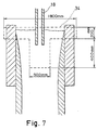
- a two-strand type continuous casting machine including a T-shaped static magnetic field generator as shown in Fig. 6, the molten steel adjusted by ladle refining and containing a C concentration of 380-500ppm, an Al concentration of 450-550ppm and an oxygen concentration of 25-28ppm, was continuously cast by three charges (300t/charge) under the condition described later. After casting, the alumina depositing states within the straight immersion nozzles were examined.
- a straight immersion nozzle 18 was used and a T-shaped static magnetic field generator 34 was disposed in such a dimensional relation as shown in Fig. 7.
- the conventional two-hole type immersion nozzle was used.
- the casting condition was as follows:
- the molten steel containing an oxygen concentration of 12-18ppm was obtained by ladle refining, wherein Al power was added within the ladle on the slag on the bath surface of the molten steel having the same composition as in Working example 4 for reducing the FeO in the slag on the molten steel in the ladle to be 2% or less in concentration.
- the above molten steel was continuously cast by three charges (300t/charge) under the same condition as in Working example 4. Thus, the alumina depositing states within the immersion nozzles were examined. In this working example, for both strands, the gas for preventing the nozzle blocking was not injected in the immersion nozzles.
- the nozzle blocking was generated at the third charge, so that the specified injection rate was not achieved and thus the casting speed was reduced from 1.6m/min to 1.1m/min.
- the casting speed was not reduced. After the casting, the inner surface of the recovered straight immersion nozzle 18 was observed, which gave the result that the alumina was deposited thereon only to a thickness of about 1-2mm.
- the continuous casting slabs obtained in Working examples 4 and 5 were hot-rolled and cold-rolled to a thickness of 0.8mm.
- the cold-rolled steel plates thus obtained were examined for the generation rate of the surface defects (total of blistering defects and sliver defects). The results are shown in Fig. 8.
- the casting experiments were made as follows: At one strand, a straight injection nozzle 18 was used and static magnetic field generators 26 and 28 were disposed on the upper and lower sides for applying the upper and lower static magnetic fields in two stages. At the other strand, the conventional two-hole type immersion nozzle was used as a comparative example. In the casting, the gas far preventing the nozzle blocking was injected at an injection rate of 10N1/min in both the above strands. The other casting condition was the same as in Working example 1.
- the generation rates of defects were obtained.
- Ther results are shown in Fig. 10.
- the generation rates of defects in this working example are indicated as circular marks (less than 0.45), triangular marks (0.45-0.7) and X marks (0.7 or more), with the generation rate of defects in the cold-rolled material obtained by the no magnetic field casting being taken as 1.
- the applied magnetic field range is more preferable as compared with the case using the one-stage magnetic field.
- the experiments were made according to the casting process using the straight nozzle of the present invention and applying the static magnetic fields in multi-stage with the gap portion, for comparing the case that the upper stage magnetic field included the meniscus and the vicinity of the discharge port of the immersion nozzle, with the case that it included only the discharge port of the immersion nozzle.
- the experiments were made using a two-strand continuous casting machine, under the following condition:
- a low carbon aluminum-killed steel containing an oxygen concentration of 28ppm was continuously cast by three charges.
- the gas for preventing the nozzle blocking was injected at an injection rate of 12N1/min.
- the comparative experiments were made between the case that the upper magnetic field generator is disposed at the height including the molten pool surface, and the case that it is disposed at the height not including the molten pool surface. Further, for comparison, the conventional casting was made.
- the generation rates of defects in this working example were standardized, with the generation rate of defects in the conventional casting being taken as 1. As is apparent from Fig. 13, according to the present invention, the generation rate of defects is smaller in the case that the static magnetic field is disposed at the height including the molten pool surface.
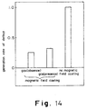
- the gas for preventing the nozzle blocking was injected at an injection rate of 12N1/min.
- Fig. 14 shows the generation rate of defects of this working example.
- the generation rate of defects is reduced in the case without the gas injection. Accordingly, by performing the casting without the gas injection, it is possible to obtain the steel plate excellent in cleanliness. Incidentally, even in the case of performing the gas injection, the generation rate of defects is sufficiently reduced.
- the continuous casting was made using a continuous casting apparatus as shown in Figs. 15(a) and 15(b). As shown in Figs. 15(a) and 15(b), there was used a straight immersion nozzle 18 having a straight discharge port 20 being opened at the leading edge of the nozzle main body. Further, upper and lower static magnetic fields 42 and 44 were applied.
- the upper static magnetic field generator 42 disposed to a continuous casting mold 10 makes quiet the surface of the molten steel supplied within the mold 10 while restricting the molten steel in the magnetic pole range, and further, equalizes the descending flow of the molten steel at a gap portion 46. Also, the lower static magnetic field generator 44 restricts the molten steel during casting.
- a straight immersion nozzle 18 was used and the upper and lower static magnetic fields 42 and 44 were applied.
- the conventional two-hole type immersion nozzle was used.
- the gas for preventing the nozzle blocking was injected at an injection rate of 10N1/min.
- the specification of the static magnetic field generator is as follows:
- the experiments were made under the same condition as in Working example 11, except that the gas injection was not performed in both the strands.
- the casting speed was 2. 0m/min, which was the same as in Working example 10.
- the molten steel was adjusted by ladle refining to be reduced in an oxygen concentration of 15-20ppm.
- the opening degree of a sliding nozzle was started to be increased at the second charge, thereby making difficult the essential flow control, and in the period near the end of the pouring process at the third charge, the desired pouring speed was not achieved due to the nozzle blocking, thereby reducing the casting speed.
- the nozzle blocking was not generated and thus the pouring speed was not reduced, as a result of which the casting speed was not reduced.
- Both the nozzles were recovered after the experiments, and were compared with each other in the blocking state of the nozzle.
- the straight immersion nozzle there was recognized the depositing alumina having a thickness of 1.0mm or less on average.
- the two-hole type immersion nozzle there was generated the alumina deposits at the discharge port, and further, the depositing states in the two holes of the immersion nozzle were not uniform, which makes unequal the right and left discharged flows to each other.
- Fig. 18 shows the results obtained from Working examples 10 and 11.
- Fig. 18 there are shown the defects on average measured by magnetic inspection per unit area of the cold-rolled steel plates which are obtained by hot-rolling and cod-rolling the slabs continuously cast. Further, after the measurement by magnetic inspection, there was examined the causes of the defects. As a result, it was revealed that the defects due to gas, the defects due to inclusions and the defects due to powder were at stake. With the generation rate of surface defects in the cold-rolled plate obtained in Working example 10 being taken as 1, the other generation rates of defects were indicated.
- Fig. 18 shows the generation rate of defects in Working examples 10 and 11 in which the casting process of the present invention is compared with the conventional casting.
- the internal defects of the slab is remarkably reduced as compared with the conventional casting.
- the blowhole defects are never generated because of no gas injection, thus obtaining the preferable results.
- the experiments were made for comparing a case of applying the two-stage static magnetic field including a gap portion, with a case of applying the one-stage static magnetic field.
- the straight immersion nozzle was used.
- the casting condition is as follows.
- the injected amount of the gas for preventing the nozzle blocking was specified to be 15N1/min in a total amount from the upper nozzle and the sliding nozzle.
- Fig. 19 shows the comparison between the experimental result obtained in the case that the two-stage static magnetic field is applied and the nozzle discharge port exists in the upper static magnetic field as shown in Fig 15, and the experimental result obtained in the case of applying the one-stage static magnetic field as shown in Fig. 16 (comparative example).
- the specifications of respective static magnetic field generators are as follows:
- Fig. 19 shows the generation rate of defects measured by magnetic inspecting device. With the generation rate of defects in the conventional casting being taken as 1, the generation rates of defects in the working example and the comparative example are shown. As a result, it becomes apparent that the generation rate of the defects in the present invention is small.
- the reason why the generation rate of defects is higher in the comparative example as compared with the present invention is that, since there is no gap in the applied magnetic field, the flow of the molten steel is difficult to be diffused as compared with the present invention, so that the discharge flow is difficult to be made the uniform descending flow. Accordingly, the inclusions and babbles are made to run along the discharge flow and to be thus trapped by the shell directly under the nozzle.
- the above comparison is made under the condition of applying the magnetic field, and accordingly, the comparative example is remarkably improved as compared with the conventional example with no magnetic field. The reason for this is that the variation in the molten pool surface is suppressed by the applied static magnetic field in the present invention and the comparative example.
- the discharge flow is not only decelerated but also diffused at the gap portion provided between the upper and lower static magnetic fields, and is made to be the uniform descending flow by the lower static magnetic field.
- the casting condition is as follows:
- Fig. 17 shows the two-stage static magnetic field generator for partially applying the static magnetic field.
- the specification of the static magnetic field generator is as follows:
- the experiment was made by disposing the above two-stage static magnetic field generator at one strand. Also, for comparison, another experiment was made at the other strand under the same condition as in Working example 10. The results are shown in Fig. 20. As is apparent from Fig. 20, it is preferable to apply the static magnetic field in a width range of 1700mm. However, even in the case of partially applying the static magnetic field, it is more preferable as compared with the conventional casting process.
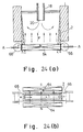
- the continuous casting was performed using a continuous casting apparatus as shown in Figs. 21(a) and 21(b).
- a continuous casting apparatus as shown in Figs. 21(a) and 21(b).
- the continuous casting was made by restricting the molten steel supplied into a continuous casting mold 10 from the nozzle in the magnetic pole range of a static magnetic field generator 58 disposed on the lower portion of the continuous casting mold 10 (see Figs. 21(a) and 21(b)).
- the molten steel adjusted by ladle refining and containing a C concentration of 400-550ppm, an Al concentration of 400-570ppm, and an oxygen concentration of 23-29ppm was continuously cast by three charges (285t/charge) under the condition described later.
- the alumina depositing states within the straight immersion nozzles were examined.
- a lower static magnetic field generator 58 was disposed in such a manner that the upper end thereof was held at the position lower than the lowermost end portion of the immersion nozzle by 100mm, and the lower end thereof was held at the position lower than the lowermost end portion of the discharge port by 600mm.
- An upper static magnetic field generator 56 was disposed in such a manner that the upper end thereof was held at the position higher than a molten steel meniscus 24 by 100mm, and the lower end thereof was held at the position lower than the meniscus 24 by 200mm.
- the conventional two-hole type immersion nozzle was used.
- the straight immersion nozzle 18 was used and the static magnetic field generators 56 and 58 were disposed.
- the casting condition is as follows:
- the molten steel containing an oxygen concentration of 12-16ppm was obtained by ladle refining, wherein Al power was added within the ladle on the slag on the bath surface of the molten steel having the same composition as in Working example 14 for reducing the FeO in the slag on the molten steel in the ladle to be 2.3% or less in concentration.
- the above molten steel was continuously cast by three charges (285t/charge) under the same condition as in Working example 14. Thus, the alumina depositing states within the immersion nozzles were examined. In this working example, for both strands, the gas for preventing the nozzle blocking was not injected in the immersion nozzles.
- the nozzle blocking was generated at the third charge, so that the specified injection rate was not achieved and thus the casting speed was reduced from 1.65m/min to 1.0m/min.
- the casting speed was not reduced. After the casting, the inner surface of the recovered straight immersion nozzle was observed, which gave the result that the alumina was deposited thereon only to a thickness of about 1-2mm.
- the continuous casting slabs obtained in Working examples 14 and 15 were hot-rolled and cold-rolled to a thickness of 1.0mm.
- the cold-rolled steel plates thus obtained were examined for the generation rate of the surface defects (total of blistering defects and sliver defects). The results are shown in Fig. 22.
- Fig. 23 is a view for explaining the construction of this working example.
- static magnetic field generating coils 60 for generating a static magnetic field in the direction perpendicular to the long side surface of the casting, and exciting rolls 62 for applying a direct current in the direction perpendicular to the short side surface of the casting.
- the static magnetic field generated at the static magnetic field generating coil 60 is applied to a widthwise central portion of the casting 2 from a suitable point under the discharge port 20 of the immersion nozzle, for example, at the position directly under the mold 10.
- the directions of the magnetic field B, the current I, and the electromagnetic force F in the molten steel are shown in a chain line, a dashed line, and two-dot chain line, respectively.
- the discharge flow of the molten steel from the nozzle is usually made to the uniform descending flow, so that the above static magnetic field excitation may be applied only in the vicinity of the widthwise central portion of the casting 2 at the position under the immersion nozzle discharge port 20, to thus restrict the flow of the molten steel.
- Fig. 24 is a view for explaining the construction of this working example 17.
- static magnetic field generating coilS 64 for generating a static magnetic field in the direction perpendicular to the long side surface of the casting, and exciting rolls 66 for applying a direct current in the direction perpendicular to the short side surface of the casting.
- the static magnetic field generated at the static magnetic field generating coils 60 is applied to the whole width of the casting 2 from a suitable point under the discharge port 20 of the immersion nozzle, for example, at the position directly under the mold 10.
- the directions of the magnetic field B, the current I, and the electromagnetic force F in the molten steel are shown in a chain line, a dashed line, and two-dot chain line, respectively.
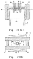
- Fig. 26 is a view for explaining the construction of this working example.
- a static magnetic generator 68 is disposed to a mold 10 at the position corresponding to the meniscus. Further, directly under the mold 10, there are provided static magnetic field generating coils 70 for generating a static magnetic field in the direction perpendicular to the long side surface of the casting, and exciting rolls 72 for applying a direct current in the direction perpendicular to the short side surface of the casting.
- the static magnetic field generated at the static magnetic field generating coil 70 is applied to the whole width of the casting 2 from a suitable point under the discharge port 20 of the immersion nozzle, for example, at the position directly under the mold 10.
- the directions of the magnetic field B, the current I, and the electromagnetic force F in the molten steel are shown in a chain line, a dashed line, and two-dot chain line, respectively.
- Fig. 28 is a view for explaining the construction of this working example 18.
- a static magnetic generator 74 is disposed to a mold 10 at the position corresponding to the meniscus. Further, directly under the mold 10, there are provided static magnetic field generating coils 76 for generating a static magnetic field in the direction perpendicular to the long side surface of the casting, and exciting rolls 80 for applying a direct current in the direction perpendicular to the short side surface of the casting.
- the static magnetic field generated at the static magnetic field generating coils 76 is applied to the whole width of the casting 2 from a suitable point under the discharge port 20 of the immersion nozzle, for example, at the position directly under the mold 10.
- the directions of the magnetic field B, the current I, and the electromagnetic force F in the molten steel are shown in a chain line, a dashed line, and two-dot chain line, respectively.
- Figs. 29 (a) and 29(b) show the construction of a main portion of a continuous casting apparatus used in this working example.
- a static magnetic generator 82 is disposed on the back surface of long side wall 14 of a continuous casting mold 10, and exciting terminals 84 are provided for applying a direct current in the direction perpendicular to the short side surface of the casting.
- exciting terminals 84 are provided for applying a direct current in the direction perpendicular to the short side surface of the casting.
- the directions of the magnetic field B, the current I, and the electromagnetic force F in the molten steel are shown in a chain line, a dashed line, and two-dot chain line, respectively
- the static magnetic field generator 82 generates the static magnetic field in the direction perpendicular to the long side surface of the casting in the molten steel within the mold, and simultaneously the exciting terminals 84 apply the direct current in the direction perpendicular to the short side surface of the casting, which makes it possible to form the electromagnetic force upwardly of the casting direction. Therefore, it is possible to disperse the flow of the downward flow from the nozzle, and hence to suppress the permeation of the inclusions and babbles in the casting.
- the slabs thus continuously cast were hot-rolled and cold-rolled to a thickness of 0.7mm.
- the cold-rolled steel plates thus obtained were subjected to continuous annealing, and then examined in an inspecting line, to be thus compared with each other in the generation rate of the sliver and blistering defects caused by steel-making.
- the generation rate of defects is represented by an equation of (weight of defective products) /(weight of inspected products)
- the working example is effective to suppress the permeation of Ar gas injected from the nozzle and the inclusions within the casting.
- the casting test was made using the straight nozzle without excitation of the static magnetic field, separately.
- the jet of the high temperature molten steel discharged from the leading edge of the nozzle was made to strongly flow in the vertical direction, and to wash the solidified shell, thereby generating the breakout, which makes impossible the casting.
- Figs. 30 (a) and 29(b) show the construction of a main portion of a continuous casting apparatus used in this working example.
- a static magnetic generator 86 is disposed on the back surface of a long side wall 14 of a continuous casting mold 10.
- exciting terminals 88 are embedded in refractories of the straight immersion nozzle 18 for applying a direct current in the direction perpendicular to the short side surface of the casting, thereby giving an electromagnetic force to the molten steel in the direction of decelerating the flow of the molten steel.
- the directions of the magnetic field B, the current I, and the electromagnetic force F in the molten steel are shown in a chain line, a dashed line, and two-dot chain line, respectively.
- the static magnetic field generator 82 generates the static magnetic field in the direction perpendicular to the long side surface of the casting in the molten steel within the mold, and simultaneously the exciting terminals 84 apply the direct current in the vicinity of the nozzle discharge port in the direction perpendicular to the short side surface of the casting, which makes it possible to form the electromagnetic force upwardly of the casting direction. Therefore, it is possible to restrict and disperse the flow of the downward flow from the nozzle, and hence to suppress the permeation of the inclusions and babbles in the casting.
- the slabs thus continuously cast were hot-rolled and cold-rolled to a thickness of 0.7mm.
- the cold-rolled steel plates thus obtained were subjected to continuous annealing, and then examined in an inspecting line, to be thus compared with each other in the generation rate of the sliver defects and blistering defects caused by steel-making.
- the generation rate of defects is represented by an equation of (weight of defective products)/(weight of inspected products)
- the working example is effective to suppress the permeation of Ar gas injected from the nozzle and the inclusions within the casting.
- the casting test was made using the a straight immersion nozzle without the excitation of the static magnetic field, separately.
- the jet of the high temperature molten steel discharged from the leading edge of the nozzle was made to strongly flow in the vertical direction, and to wash the solidified shell, thereby generating the breakout, which makes impossible the casting.
- the steel of the same kind as in Working example and containing a total oxygen amount of 20ppm or less was continuous cast under the same condition as in Working example 21 except that Ar gas was not injected in the immersion nozzle.
- the cold-rolled steel plates thus obtained were examined.
- the steel plates continuously cast according to the present invention rolled and annealed, there was obtained the preferable results of sliver defects (0.01%) and blistering defects (0%).
- the desired pouring speed was not achieved at third charge because of the nozzle blocking, and the casting speed was reduced from 1.6m/min to 1.2m/min.
- the casting speed was not reduced, and only the alumina depositing layer of 1-2mm and a slight blocking were recognized on the inner surface of the straight nozzle after casting.
Landscapes
- Engineering & Computer Science (AREA)
- Mechanical Engineering (AREA)
- Continuous Casting (AREA)
Claims (9)
- Verfahren zum Stranggießen von Stahltafeln mit den Schritten:Zuführen von Stahlschmelze von einer Gießwanne zu einer Stranggussform, unter Benutzung einer Gerade-Eintauchdüse,Anordnen eines Statikmagnetfeld-Generators an den hinteren Flächen der langen Seitenwände der Form in der Höhe, die den Pegel des Auslassanschlusses der Gerade-Eintauchdüse enthält;Gießen der Stahlschmelze unter Erzeugen eines statischen Magnetfeldes in der Richtung von einer langen Seitenwand zur anderen langen Seitenwand der Form;wobei das Gießen in der Eintauchdüse ausgeführt wird; undwobei gemäß einer angegebenen Auslass-Strömungsgeschwindigkeit (v) (m/s) [Strömungsrate der Stahlschmelze (m3/s) / Düsenquerschnittsfläche (m2)] von der Auslassöffnung der Gerade-Eintauchdüse eine Beziehung zwischen einer Magnetflussdichte B(T) und einem angelegten Magnetfeldbereich L (mm) vertikal unter der Auslassöffnung der Gerade-Eintauchdüse wie folgt festgesetzt wird:v ≤ 0,9 (m/s), B x L ≥ 25,
wobei B ≥ 0,07 T, L ≥ 80 mmv ≤ 1,5 (m/s), B x L ≥ 27,
wobei B ≥ 0,08 T, L ≥ 90 mmv ≤ 2,0 (m/s), B x L ≥ 30,
wobei B ≥ 0,09 T, L ≥ 100 mmv ≤ 2,5 (m/s), B x L ≥ 33,
wobei B ≥ 0,09 T,L ≥ 110 mmv ≤ 3,0 (m/s), B x L ≥ 35,
wobei B ≥ 0,1 T, L ≥ 110 mmv ≤ 3,8 (m/s), B x L ≥ 36,
wobei B ≥ 0,11 T, L ≥ 120 mmv ≤ 4,8 (m/s), B x L ≥ 38,
wobei B ≥ 0,12 T, L ≥ 120 mmv ≤ 5,5 (m/s), B x L ≥ 40,
wobei B ≥ 0,13 T, L ≥ 130 mm. - Verfahren zum Stranggießen von Stahlplatten nach Anspruch 1, bei dem das Gießen unter Anlegen eines Magnetfelds über die gesamte Breite der langen Seitenwand der Form durchgeführt wird.
- Verfahren zum Stranggießen von Stahlplatten nach Anspruch 1 oder 2, bei dem das Gießen unter Anlegen eines Magnetfelds oberhalb des Meniskus in der Form ausgeführt wird.
- Verfahren zum Stranggießen von Stahlplatten nach Anspruch 1, wobei der Statikmagnetfeld-Generator einen I-förmigen Statikmagnetfeld-Generator zum Erzeugen statischer Magnetfelder an den oberen und unteren Abschnitten der Form über die gesamte Breite und zu dem mittleren Abschnitt der Form in der engen Breite umfasst.
- Verfahren zum Stranggießen von Stahlplatten nach Anspruch 1, bei dem der Statik-Magnetfeld-Generator einen T-förmigen Statik-Magnetfeld-Generator zum Erzeugen statischer Magnetfelder an dem Meniskusabschnitt der Form über die gesamte Breite und zu dem breitenweise zentralen Abschnitt umfasst, der die Auslassöffnung der Eintauchdüse enthält.
- Verfahren zum Stranggießen von Stahlplatten nach Anspruch 1, gekennzeichnet durch Anordnen mindestens eines zweiten Statikmagnetfeld-Generators mit einem gewissen Abstand unter dem ersten Statik-Magnetfeld-Generator zum Ausbilden eines Spaltabschnitts, der in einem magnetfeldfreien Zustand ist, zwischen den ersten und den zweiten Statik-Magnetfeld-Generatoren.
- Verfahren zum Stranggießen von Stahlplatten nach Anspruch 1,
gekennzeichnet durch
Gießen des Stahls unter Anlegen eines Gleichstroms an die Umgebung der Auslassöffnung der Gerade-Eintauchdüse in der Richtung senkrecht zur kurzen Seitenfläche des Gusses. - Verfahren zum Stranggießen von Stahlplatten nach Anspruch 7, bei dem das Mittel zum Anlegen eines Gleichstroms ausgelegt ist, einen Gleichstrom zwischen in der Stahlschmelze in der Umgebung der Vorderkante der geraden Eintauchdüse aufgehängten Beaufschlagungsklemmen anzulegen.
- Verfahren zum Stranggießen von Stahlplatten nach Anspruch 7, bei dem das Mittel zum Anlegen eines Gleichstroms ausgelegt ist, einen Gleichstrom zwischen in feuerfestem Material des Vorderkantenabschnitts der geraden Eintauchdüse angebrachten Beaufschlagungsklemmen anzulegen.
Applications Claiming Priority (22)
| Application Number | Priority Date | Filing Date | Title |
|---|---|---|---|
| JP24607491 | 1991-09-25 | ||
| JP246077/91 | 1991-09-25 | ||
| JP24607991A JP2888312B2 (ja) | 1991-09-25 | 1991-09-25 | 静磁場による鋼スラブの連続鋳造法 |
| JP3246077A JPH0577007A (ja) | 1991-09-25 | 1991-09-25 | 静磁場を用いる鋼スラブの連続鋳造法 |
| JP24607491A JP2859764B2 (ja) | 1991-09-25 | 1991-09-25 | 静磁場を用いる鋼スラブの連続鋳造方法 |
| JP24607791 | 1991-09-25 | ||
| JP246079/91 | 1991-09-25 | ||
| JP246074/91 | 1991-09-25 | ||
| JP24607991 | 1991-09-25 | ||
| JP25730991 | 1991-10-04 | ||
| JP257309/91 | 1991-10-04 | ||
| JP257312/91 | 1991-10-04 | ||
| JP3257309A JPH0596345A (ja) | 1991-10-04 | 1991-10-04 | 静磁場通電法を用いた鋼の連続鋳造方法 |
| JP25731291 | 1991-10-04 | ||
| JP3257312A JPH0596346A (ja) | 1991-10-04 | 1991-10-04 | 静磁場通電法を用いた鋼の連続鋳造方法 |
| JP49177/92 | 1992-03-06 | ||
| JP4917792A JP2953857B2 (ja) | 1992-03-06 | 1992-03-06 | 静磁場を使用した連続鋳造方法 |
| JP4917792 | 1992-03-06 | ||
| JP12793892 | 1992-04-22 | ||
| JP4127938A JP2750320B2 (ja) | 1992-04-22 | 1992-04-22 | 静磁場を使用した連続鋳造方法 |
| JP127938/92 | 1992-04-22 | ||
| PCT/JP1992/001221 WO1993005907A1 (fr) | 1991-09-25 | 1992-09-25 | Procede pour le coulage en continu de brames d'acier grace a l'utilisation d'un champ electromagnetique |
Publications (3)
| Publication Number | Publication Date |
|---|---|
| EP0568699A1 EP0568699A1 (de) | 1993-11-10 |
| EP0568699A4 EP0568699A4 (en) | 1994-06-01 |
| EP0568699B1 true EP0568699B1 (de) | 2000-02-09 |
Family
ID=27564716
Family Applications (1)
| Application Number | Title | Priority Date | Filing Date |
|---|---|---|---|
| EP92919861A Expired - Lifetime EP0568699B1 (de) | 1991-09-25 | 1992-09-25 | Verfahren zum stranggiessen von stahl unter verwendung von magnetfeldern |
Country Status (6)
| Country | Link |
|---|---|
| US (1) | US5570736A (de) |
| EP (1) | EP0568699B1 (de) |
| KR (1) | KR0184240B1 (de) |
| CA (1) | CA2096737C (de) |
| DE (1) | DE69230666T2 (de) |
| WO (1) | WO1993005907A1 (de) |
Families Citing this family (8)
| Publication number | Priority date | Publication date | Assignee | Title |
|---|---|---|---|---|
| SE501935C2 (sv) * | 1993-11-10 | 1995-06-26 | Asea Brown Boveri | Sätt och anordning för att bromsa en smältas rörelse vid gjutning i kokill |
| US6341642B1 (en) | 1997-07-01 | 2002-01-29 | Ipsco Enterprises Inc. | Controllable variable magnetic field apparatus for flow control of molten steel in a casting mold |
| US6211477B1 (en) | 1998-02-26 | 2001-04-03 | Becton Dickinson And Company | Electrostatic deceleration system for flow cytometer |
| KR100376504B1 (ko) * | 1998-08-04 | 2004-12-14 | 주식회사 포스코 | 연속주조방법및이에이용되는연속주조장치 |
| US20050045303A1 (en) * | 2003-08-29 | 2005-03-03 | Jfe Steel Corporation, A Corporation Of Japan | Method for producing ultra low carbon steel slab |
| US8362086B2 (en) | 2005-08-19 | 2013-01-29 | Merial Limited | Long acting injectable formulations |
| KR101250101B1 (ko) * | 2010-03-10 | 2013-04-03 | 제이에프이 스틸 가부시키가이샤 | 강의 연속 주조 방법 및 강판의 제조 방법 |
| CN102373367A (zh) * | 2010-08-26 | 2012-03-14 | 宝山钢铁股份有限公司 | 一种用于快循环同步加速器的冷轧电磁钢板及其制造方法 |
Family Cites Families (12)
| Publication number | Priority date | Publication date | Assignee | Title |
|---|---|---|---|---|
| JPS57127556A (en) * | 1981-01-29 | 1982-08-07 | Nippon Kokan Kk <Nkk> | Method for horizontal casting of steel |
| JPS5855157A (ja) * | 1981-09-28 | 1983-04-01 | Sumitomo Metal Ind Ltd | 連続鋳造の注入流制御方法および装置 |
| JPS611459A (ja) * | 1984-06-12 | 1986-01-07 | Kawasaki Steel Corp | 鋼の連続鋳造方法 |
| JPS61193754A (ja) * | 1985-02-22 | 1986-08-28 | Sumitomo Metal Ind Ltd | 連続鋳造鋼片の熱間割れ防止方法 |
| JPS623857A (ja) * | 1985-06-28 | 1987-01-09 | Kawasaki Steel Corp | 単孔式浸漬ノズルを使用した連続鋳造方法 |
| JPS62130752A (ja) * | 1985-12-04 | 1987-06-13 | Kawasaki Steel Corp | ブル−ムもしくはビレツトの連続鋳造方法 |
| SU1371764A1 (ru) * | 1986-05-28 | 1988-02-07 | Всесоюзный научно-исследовательский институт металлургической теплотехники | Способ измерени скорости течени расплавленного металла в жидкой фазе слитка при непрерывной разливке в зоне установки электромагнитного перемешивани |
| JPS63260652A (ja) * | 1987-04-20 | 1988-10-27 | Kawasaki Steel Corp | 連続鋳造におけるモ−ルドパウダ−の巻き込み防止方法 |
| JPH03142049A (ja) * | 1989-10-30 | 1991-06-17 | Kawasaki Steel Corp | 静磁場を用いた鋼の連続鋳造方法及びその装置 |
| KR930002836B1 (ko) * | 1989-04-27 | 1993-04-10 | 가와사끼 세이데쓰 가부시까가이샤 | 정자장을 이용한 강철의 연속 주조방법 |
| JPH0390257A (ja) * | 1989-06-27 | 1991-04-16 | Kobe Steel Ltd | スラブの連続鋳造における鋳型内電磁撹拌方法 |
| EP0523837B1 (de) * | 1991-06-05 | 1997-02-19 | Kawasaki Steel Corporation | Stranggiessen von Stahl |
-
1992
- 1992-09-25 CA CA002096737A patent/CA2096737C/en not_active Expired - Fee Related
- 1992-09-25 KR KR1019930701482A patent/KR0184240B1/ko not_active Expired - Fee Related
- 1992-09-25 EP EP92919861A patent/EP0568699B1/de not_active Expired - Lifetime
- 1992-09-25 US US08/064,084 patent/US5570736A/en not_active Expired - Fee Related
- 1992-09-25 WO PCT/JP1992/001221 patent/WO1993005907A1/ja not_active Ceased
- 1992-09-25 DE DE69230666T patent/DE69230666T2/de not_active Expired - Fee Related
Also Published As
| Publication number | Publication date |
|---|---|
| US5570736A (en) | 1996-11-05 |
| DE69230666T2 (de) | 2000-06-08 |
| CA2096737C (en) | 2004-01-27 |
| WO1993005907A1 (fr) | 1993-04-01 |
| EP0568699A1 (de) | 1993-11-10 |
| EP0568699A4 (en) | 1994-06-01 |
| KR930702100A (ko) | 1993-09-08 |
| CA2096737A1 (en) | 1993-03-26 |
| DE69230666D1 (de) | 2000-03-16 |
| KR0184240B1 (ko) | 1999-04-01 |
Similar Documents
| Publication | Publication Date | Title |
|---|---|---|
| EP0401504B2 (de) | Verfahren und Vorrichtung zum Stranggiessen | |
| EP0568699B1 (de) | Verfahren zum stranggiessen von stahl unter verwendung von magnetfeldern | |
| JPH02284750A (ja) | 静磁場を用いる鋼の連続鋳造方法 | |
| EP0523837B1 (de) | Stranggiessen von Stahl | |
| AU716170B2 (en) | Magnetic brake apparatus for continuous casting mold and continuous casting method using the same | |
| JPS62254954A (ja) | 連続鋳造における鋳型内溶鋼流動の抑制方法 | |
| JPH0577007A (ja) | 静磁場を用いる鋼スラブの連続鋳造法 | |
| Nakanishi | Japanese state of the art continuous casting process | |
| JP2750320B2 (ja) | 静磁場を使用した連続鋳造方法 | |
| JP2856960B2 (ja) | 進行磁場と静磁場による鋼スラブの連続鋳造方法 | |
| JP5125663B2 (ja) | スラブ鋳片の連続鋳造方法 | |
| JPH11285788A (ja) | 厚鋼板用大断面鋳片の連続鋳造方法 | |
| JPH0584551A (ja) | 静磁場を用いる鋼の連続鋳造方法 | |
| JP2953857B2 (ja) | 静磁場を使用した連続鋳造方法 | |
| JP3491099B2 (ja) | 静磁場を用いた鋼の連続鋳造方法 | |
| JP2856959B2 (ja) | 進行磁場と静磁場を用いた鋼スラブの連続鋳造方法 | |
| JP2925374B2 (ja) | 静磁場による鋼スラブの連続鋳造方法 | |
| JP2888312B2 (ja) | 静磁場による鋼スラブの連続鋳造法 | |
| JPH0596346A (ja) | 静磁場通電法を用いた鋼の連続鋳造方法 | |
| JPH0596345A (ja) | 静磁場通電法を用いた鋼の連続鋳造方法 | |
| JP2859764B2 (ja) | 静磁場を用いる鋼スラブの連続鋳造方法 | |
| JP3095710B2 (ja) | 静磁場を使用した連続鋳造方法 | |
| JP2856947B2 (ja) | 進行磁場を用いる鋼スラブの連続鋳造方法 | |
| JPH0596350A (ja) | 静磁場通電法を用いた鋼の連続鋳造方法 | |
| JPH0584552A (ja) | 静磁場を用いる鋼の連続鋳造方法 |
Legal Events
| Date | Code | Title | Description |
|---|---|---|---|
| PUAI | Public reference made under article 153(3) epc to a published international application that has entered the european phase |
Free format text: ORIGINAL CODE: 0009012 |
|
| AK | Designated contracting states |
Kind code of ref document: A1 Designated state(s): DE FR GB SE |
|
| 17P | Request for examination filed |
Effective date: 19930730 |
|
| A4 | Supplementary search report drawn up and despatched | ||
| AK | Designated contracting states |
Kind code of ref document: A4 Designated state(s): DE FR GB SE |
|
| 17Q | First examination report despatched |
Effective date: 19961122 |
|
| GRAG | Despatch of communication of intention to grant |
Free format text: ORIGINAL CODE: EPIDOS AGRA |
|
| GRAG | Despatch of communication of intention to grant |
Free format text: ORIGINAL CODE: EPIDOS AGRA |
|
| GRAG | Despatch of communication of intention to grant |
Free format text: ORIGINAL CODE: EPIDOS AGRA |
|
| GRAH | Despatch of communication of intention to grant a patent |
Free format text: ORIGINAL CODE: EPIDOS IGRA |
|
| GRAH | Despatch of communication of intention to grant a patent |
Free format text: ORIGINAL CODE: EPIDOS IGRA |
|
| GRAA | (expected) grant |
Free format text: ORIGINAL CODE: 0009210 |
|
| RIN1 | Information on inventor provided before grant (corrected) |
Inventor name: FUJII, TETSUYA, TECHNICAL RESEARCH DIVISION OF Inventor name: TAGUCHI, SEIJI, TECHNICAL RESEARCH DIVISION OF Inventor name: BESSHO, NAGAYASU, TECHNICAL RESEARCH DIVISION OF Inventor name: YAMAZAKI, HISAO, TECHNICAL RESEARCH DIVISION OF Inventor name: NARA, SEIOKOU, TECHNICAL RESEARCH DIVISION |
|
| AK | Designated contracting states |
Kind code of ref document: B1 Designated state(s): DE FR GB SE |
|
| ET | Fr: translation filed | ||
| REF | Corresponds to: |
Ref document number: 69230666 Country of ref document: DE Date of ref document: 20000316 |
|
| PLBE | No opposition filed within time limit |
Free format text: ORIGINAL CODE: 0009261 |
|
| STAA | Information on the status of an ep patent application or granted ep patent |
Free format text: STATUS: NO OPPOSITION FILED WITHIN TIME LIMIT |
|
| 26N | No opposition filed | ||
| REG | Reference to a national code |
Ref country code: GB Ref legal event code: IF02 |
|
| PGFP | Annual fee paid to national office [announced via postgrant information from national office to epo] |
Ref country code: SE Payment date: 20030904 Year of fee payment: 12 |
|
| PGFP | Annual fee paid to national office [announced via postgrant information from national office to epo] |
Ref country code: FR Payment date: 20030909 Year of fee payment: 12 |
|
| PGFP | Annual fee paid to national office [announced via postgrant information from national office to epo] |
Ref country code: GB Payment date: 20030924 Year of fee payment: 12 |
|
| PGFP | Annual fee paid to national office [announced via postgrant information from national office to epo] |
Ref country code: DE Payment date: 20031002 Year of fee payment: 12 |
|
| PG25 | Lapsed in a contracting state [announced via postgrant information from national office to epo] |
Ref country code: GB Free format text: LAPSE BECAUSE OF NON-PAYMENT OF DUE FEES Effective date: 20040925 |
|
| PG25 | Lapsed in a contracting state [announced via postgrant information from national office to epo] |
Ref country code: SE Free format text: LAPSE BECAUSE OF NON-PAYMENT OF DUE FEES Effective date: 20040926 |
|
| PG25 | Lapsed in a contracting state [announced via postgrant information from national office to epo] |
Ref country code: DE Free format text: LAPSE BECAUSE OF NON-PAYMENT OF DUE FEES Effective date: 20050401 |
|
| EUG | Se: european patent has lapsed | ||
| GBPC | Gb: european patent ceased through non-payment of renewal fee |
Effective date: 20040925 |
|
| PG25 | Lapsed in a contracting state [announced via postgrant information from national office to epo] |
Ref country code: FR Free format text: LAPSE BECAUSE OF NON-PAYMENT OF DUE FEES Effective date: 20050531 |
|
| REG | Reference to a national code |
Ref country code: FR Ref legal event code: ST |