EP0563351B1 - Sicherheitseinrichtung für intravenösen schlauch - Google Patents
Sicherheitseinrichtung für intravenösen schlauch Download PDFInfo
- Publication number
- EP0563351B1 EP0563351B1 EP92921177A EP92921177A EP0563351B1 EP 0563351 B1 EP0563351 B1 EP 0563351B1 EP 92921177 A EP92921177 A EP 92921177A EP 92921177 A EP92921177 A EP 92921177A EP 0563351 B1 EP0563351 B1 EP 0563351B1
- Authority
- EP
- European Patent Office
- Prior art keywords
- tube
- slide clamp
- clamp
- pump
- occluding
- Prior art date
- Legal status (The legal status is an assumption and is not a legal conclusion. Google has not performed a legal analysis and makes no representation as to the accuracy of the status listed.)
- Expired - Lifetime
Links
- 238000001990 intravenous administration Methods 0.000 title claims description 8
- 230000002572 peristaltic effect Effects 0.000 claims abstract description 37
- 230000000414 obstructive effect Effects 0.000 claims abstract description 25
- 230000003287 optical effect Effects 0.000 claims description 25
- 230000001105 regulatory effect Effects 0.000 claims description 23
- 230000004044 response Effects 0.000 claims description 17
- 230000005484 gravity Effects 0.000 claims description 14
- 238000003780 insertion Methods 0.000 claims description 10
- 230000037431 insertion Effects 0.000 claims description 10
- 230000007246 mechanism Effects 0.000 claims description 8
- 238000005086 pumping Methods 0.000 claims description 8
- 230000009471 action Effects 0.000 claims description 5
- 230000002093 peripheral effect Effects 0.000 claims description 5
- 230000002265 prevention Effects 0.000 claims description 5
- 230000004913 activation Effects 0.000 claims 2
- 235000010627 Phaseolus vulgaris Nutrition 0.000 claims 1
- 244000046052 Phaseolus vulgaris Species 0.000 claims 1
- 230000001419 dependent effect Effects 0.000 claims 1
- 239000012530 fluid Substances 0.000 description 15
- 230000036541 health Effects 0.000 description 9
- 230000000717 retained effect Effects 0.000 description 8
- 239000003978 infusion fluid Substances 0.000 description 5
- 239000000243 solution Substances 0.000 description 5
- 239000012190 activator Substances 0.000 description 3
- 238000001802 infusion Methods 0.000 description 3
- 239000004800 polyvinyl chloride Substances 0.000 description 3
- FAPWRFPIFSIZLT-UHFFFAOYSA-M Sodium chloride Chemical compound [Na+].[Cl-] FAPWRFPIFSIZLT-UHFFFAOYSA-M 0.000 description 2
- 208000027418 Wounds and injury Diseases 0.000 description 2
- 238000004891 communication Methods 0.000 description 2
- 230000006378 damage Effects 0.000 description 2
- 239000003814 drug Substances 0.000 description 2
- 229940079593 drug Drugs 0.000 description 2
- 230000000694 effects Effects 0.000 description 2
- 229920002457 flexible plastic Polymers 0.000 description 2
- 208000014674 injury Diseases 0.000 description 2
- 239000000463 material Substances 0.000 description 2
- 239000011780 sodium chloride Substances 0.000 description 2
- 238000011144 upstream manufacturing Methods 0.000 description 2
- 229920004943 Delrin® Polymers 0.000 description 1
- WQZGKKKJIJFFOK-GASJEMHNSA-N Glucose Natural products OC[C@H]1OC(O)[C@H](O)[C@@H](O)[C@@H]1O WQZGKKKJIJFFOK-GASJEMHNSA-N 0.000 description 1
- 208000006440 Open Bite Diseases 0.000 description 1
- 239000004743 Polypropylene Substances 0.000 description 1
- 230000003213 activating effect Effects 0.000 description 1
- 230000008901 benefit Effects 0.000 description 1
- WQZGKKKJIJFFOK-VFUOTHLCSA-N beta-D-glucose Chemical compound OC[C@H]1O[C@@H](O)[C@H](O)[C@@H](O)[C@@H]1O WQZGKKKJIJFFOK-VFUOTHLCSA-N 0.000 description 1
- 238000010276 construction Methods 0.000 description 1
- 238000010586 diagram Methods 0.000 description 1
- 230000009977 dual effect Effects 0.000 description 1
- 239000003792 electrolyte Substances 0.000 description 1
- 239000011521 glass Substances 0.000 description 1
- 239000008103 glucose Substances 0.000 description 1
- 230000002401 inhibitory effect Effects 0.000 description 1
- 238000002347 injection Methods 0.000 description 1
- 239000007924 injection Substances 0.000 description 1
- 230000031700 light absorption Effects 0.000 description 1
- 238000012986 modification Methods 0.000 description 1
- 230000004048 modification Effects 0.000 description 1
- 229920000728 polyester Polymers 0.000 description 1
- 229920005644 polyethylene terephthalate glycol copolymer Polymers 0.000 description 1
- -1 polypropylene Polymers 0.000 description 1
- 229920001155 polypropylene Polymers 0.000 description 1
- 229920000915 polyvinyl chloride Polymers 0.000 description 1
- 238000010926 purge Methods 0.000 description 1
- 238000002310 reflectometry Methods 0.000 description 1
- 230000001954 sterilising effect Effects 0.000 description 1
- 238000004659 sterilization and disinfection Methods 0.000 description 1
- 210000003462 vein Anatomy 0.000 description 1
Images


Classifications
-
- A—HUMAN NECESSITIES
- A61—MEDICAL OR VETERINARY SCIENCE; HYGIENE
- A61M—DEVICES FOR INTRODUCING MEDIA INTO, OR ONTO, THE BODY; DEVICES FOR TRANSDUCING BODY MEDIA OR FOR TAKING MEDIA FROM THE BODY; DEVICES FOR PRODUCING OR ENDING SLEEP OR STUPOR
- A61M39/00—Tubes, tube connectors, tube couplings, valves, access sites or the like, specially adapted for medical use
- A61M39/22—Valves or arrangement of valves
- A61M39/28—Clamping means for squeezing flexible tubes, e.g. roller clamps
- A61M39/281—Automatic tube cut-off devices, e.g. squeezing tube on detection of air
-
- A—HUMAN NECESSITIES
- A61—MEDICAL OR VETERINARY SCIENCE; HYGIENE
- A61M—DEVICES FOR INTRODUCING MEDIA INTO, OR ONTO, THE BODY; DEVICES FOR TRANSDUCING BODY MEDIA OR FOR TAKING MEDIA FROM THE BODY; DEVICES FOR PRODUCING OR ENDING SLEEP OR STUPOR
- A61M39/00—Tubes, tube connectors, tube couplings, valves, access sites or the like, specially adapted for medical use
- A61M39/22—Valves or arrangement of valves
- A61M39/28—Clamping means for squeezing flexible tubes, e.g. roller clamps
- A61M39/286—Wedge clamps, e.g. roller clamps with inclined guides
- A61M39/287—Wedge formed by a slot having varying width, e.g. slide clamps
-
- A—HUMAN NECESSITIES
- A61—MEDICAL OR VETERINARY SCIENCE; HYGIENE
- A61M—DEVICES FOR INTRODUCING MEDIA INTO, OR ONTO, THE BODY; DEVICES FOR TRANSDUCING BODY MEDIA OR FOR TAKING MEDIA FROM THE BODY; DEVICES FOR PRODUCING OR ENDING SLEEP OR STUPOR
- A61M2205/00—General characteristics of the apparatus
- A61M2205/60—General characteristics of the apparatus with identification means
-
- A—HUMAN NECESSITIES
- A61—MEDICAL OR VETERINARY SCIENCE; HYGIENE
- A61M—DEVICES FOR INTRODUCING MEDIA INTO, OR ONTO, THE BODY; DEVICES FOR TRANSDUCING BODY MEDIA OR FOR TAKING MEDIA FROM THE BODY; DEVICES FOR PRODUCING OR ENDING SLEEP OR STUPOR
- A61M5/00—Devices for bringing media into the body in a subcutaneous, intra-vascular or intramuscular way; Accessories therefor, e.g. filling or cleaning devices, arm-rests
- A61M5/14—Infusion devices, e.g. infusing by gravity; Blood infusion; Accessories therefor
- A61M5/142—Pressure infusion, e.g. using pumps
- A61M5/14212—Pumping with an aspiration and an expulsion action
- A61M5/14228—Pumping with an aspiration and an expulsion action with linear peristaltic action, i.e. comprising at least three pressurising members or a helical member
-
- Y—GENERAL TAGGING OF NEW TECHNOLOGICAL DEVELOPMENTS; GENERAL TAGGING OF CROSS-SECTIONAL TECHNOLOGIES SPANNING OVER SEVERAL SECTIONS OF THE IPC; TECHNICAL SUBJECTS COVERED BY FORMER USPC CROSS-REFERENCE ART COLLECTIONS [XRACs] AND DIGESTS
- Y10—TECHNICAL SUBJECTS COVERED BY FORMER USPC
- Y10S—TECHNICAL SUBJECTS COVERED BY FORMER USPC CROSS-REFERENCE ART COLLECTIONS [XRACs] AND DIGESTS
- Y10S128/00—Surgery
- Y10S128/12—Pressure infusion
Definitions
- the present invention relates in general to a safety apparatus utilizable in a peristaltic intravenous infusion pump, and with a slide clamp to control the flow of medical fluid to an I.V. tubing.
- Intravenous fluids to a patient is well known in the art.
- a solution such as saline, glucose or electrolyte in a glass or flexible container is fed to a patient's venous access site via a length of flexible plastic I.V. tubing such as polyvinyl chloride (PVC) tubing.
- I.V. tubing such as polyvinyl chloride (PVC) tubing.
- the rate of flow of the fluid is controlled by a roller clamp which is adjusted to restrict the flow lumen of the I.V. tubing until the desired flow rate is obtained.
- Flow from the container to the patient may also be regulated by means other than a roller clamp. It is becoming more and more common to use an electronically controlled pump.
- One type of pump that is used for intravenous fluid administration is a peristaltic-type pump.
- peristaltic pumping action is particularly well suited for the medical field. This is because peristaltic pumping action can be applied externally of the I.V. tubing carrying the intravenous fluid. This maintains the sterile condition of the intravenous fluid within the I.V. tubing while imparting fluid propulsion on the fluid. The peristaltic pumping action can also be applied on any point on the I.V. tubing.
- a driving motor is connected to an array of cams which are angularly spaced from each other.
- the cams in turn drive cam followers which are connected to corresponding pressure fingers.
- These elements cooperate to impart a linear wave motion on the pressure fingers.
- a pressure plate is secured juxtaposed to and spaced from the pressure fingers. The pressure plate holds the I.V. tubing against the reciprocating pressure fingers to impart the wave motion on the I.V. tubing to propel the fluid.
- a driving motor is connected via an armature to at least one roller member.
- the driving motor imparts a circular rotation on the armature which actuates the roller member.
- a semicircular pressure plate having the same center point as the armature is provided with the I.V. tubing located between the roller member and the pressure plate. The pressure plate holds the I.V. tubing against the roller member which imparts a circular motion on the I.V. tubing to propel the fluid.
- peristaltic pumps One drawback of the use of peristaltic pumps is that, because when loaded into the pump the peristaltic action drives the propulsion of the fluid, prior to loading into the pump, the I.V. tubing is often left in an open condition. While a straightforward solution to this problem is to simply provide a roller or other flow clamp on the I.V. tubing to occlude the I.V. tubing prior to loading and after removal, this creates the possibility that the health care professional loading the I.V. tubing into the peristaltic pump will forget to open the I.V. tubing after loading has been completed.
- Prior art slide clamps generally include a regulating aperture defining an occluding slot and a non-occluding passage.
- An I.V. tube inserted through the regulating aperture in an operative position is slidable transverse to the length of the tube between the non-occluding passage and the occluding slot to control the flow of fluid through the lumen of the I.V. tube.
- prior art slide clamps tend to slide longitudinally of the I.V. tube under the effect of gravity. Often, this sliding makes it difficult and cumbersome for medical personnel to quickly locate the slide clamp to occlude flow at a desired position along the length of the I.V. tube.
- the tube contacting surface of the flow regulating aperture typically extends over the entire depth of the slide clamp.
- prior art slide clamps leave a relatively wide surface contacting an I.V. tube in an operative position, providing a significant frictional force opposing sliding of an I.V. tube relative to the slide clamp between the non-occluding passage and the occluding slot. Both of these features make it relatively difficult to use prior art slide clamps with a safety mechanism for use in a peristaltic pump.
- a safety mechanism for use in a peristaltic pump which preferably utilizes a disposable I.V. slide clamp carried by I.V. tubing which can be located longitudinally of the tube and not displaced solely by force of gravity and which can be slid between a non-occluding passage and an occluded slot with minimal force.
- the safety mechanism would preferably prevent both an inadvertent free flow condition prior to loading or after removal of an I.V. tube in a peristaltic pump and prevent inadvertent occlusion of a loaded I.V. tube.
- the present invention provides a safety apparatus as set out in claim 1, for use with an IV pump.
- the pre-amble of claim 1 is based on US-A-5 017 192.
- the present invention provides, in a preferred embodiment, an apparatus for use in a peristaltic pump which prevents an inadvertent free flow condition prior to loading or after removal of an I.V. tube in a peristaltic pump and which also prevents the inadvertent occlusion of a loaded I.V. tube in a peristaltic pump, the apparatus including a standard I.V. tube having a slide clamp provided thereon.
- the apparatus includes an I.V. tube groove into which the I.V. tubing is positioned, a slide clamp receiving area into which the slide clamp is inserted, and a biased sliding member which the inserted slide clamp engages such that the I.V. tubing cannot be loaded into the apparatus without the slide clamp occluding the I.V. tubing.
- the sliding member preferably includes a cam portion which interacts with a cam follower on a pair of retainer arms which causes the retainer arms to pivot into an open position.
- the peristaltic pumping door is closed which 1) secures the I.V. tubing in the I.V. tube groove, 2) disengages the loaded sliding member which forces the slide clamp into a free flow or non-occluding state with respect to the I.V. tube, 3) engages the retaining arms which secures the now open slide clamp in the apparatus, and 4) positions a safety clamp in a ready but open state.
- US-A-4689043 discloses an IV tube activator for use with a peristaltic IV infusion pump.
- the tube is associated with a slide clamp.
- the activator comprises means that requires the clamping of the tube upon engagement of the IV tube with the pump and upon any subsequent disengagement of the IV tube from the pump.
- the activator further comprises means which simultaneously move the clamp to open the IV tube when the pump is being operated.
- US-A-5017192 discloses a safety apparatus for a pump in which a wedge is used to move arms of a slide clamp apart, thereby un-occluding an IV tube on which the clamp is held.
- a dial is rotated by the operator to move the clamp towards, and into engagement with the wedge.
- the clamp Prior to rotating the dial, the clamp is engaged by the operator with a retainer arm to retain the clamp in the correct position in the apparatus.
- the door is opened which causes the safety clamp to occlude the I.V tube.
- the slide clamp Prior to removal of the I.V. tube, the slide clamp must again be engaged into an occluded state with respect to the I.V. tube, thereby 1) reloading the slide member, 2) pivoting via the cam and cam followers the retainer arms into the open position and 3) freeing the safety clamp so that it can be positioned in the latched open position. It is only after these steps have been completed with the slide clamp occluding the I.V. tube that the I.V. tube and the slide clamp can be removed.
- a non-obstructive sensor within the clamp receiving area is in a first state in response to the presence of the clamp in a selected position in the slide clamp receiving area and a second state in response to the absence of the slide clamp from the selected position.
- a device operatively associated with the non-obstructive sensor disables the pump in response to the non-obstructive sensor being in the second state.
- the non-obstructive sensor can include a reflective pad on the clamp and a light source in the clamp receiving area directing a beam of light onto the pad.
- An optical sensor receives light reflected off the pad, the optical sensor being in a first state in response to receiving the selected portion of a beam of light and a second state in response to not receiving the selected portion of a beam of light.
- the non-obstructive sensor may further include a device for determining compatibility of the slide clamp with the sensor, the non-obstructive sensor being in a first state when the clamp is compatible with the safety apparatus and a second state when the clamp is not compatible with the safety apparatus.
- a structure is preferably provided on the slide clamp body for facilitating automated identification of the clamp.
- the automated identification structure may be a surface pad which reflects a selected portion of a beam of light shined onto the pad.
- An optical sensor is able to identify the slide clamp based upon the reflected portion of the beam of light.
- the clamp can be in combination with an optical identifying structure including a lamp omitting a selected beam of light, the beam of light being directed onto the surface pad.
- the surface pad absorbs a portion of the beam of light and reflects a portion of the beam of light.
- An optical sensor receives the reflected portion of the beam of light, the optical sensor being in a first state in response to receiving the selected portion of the beam of light and a second state in response to not receiving the selected portion of the beam of light.
- An indicator operatively associated with the optical sensor indicates whether the optical sensor is in the first or second state.
- the slide clamp preferably has a body having oppositely facing top and bottom surfaces, with a regulating aperture defined by an internal peripheral wall in the body and extending transversely between the top and bottom surfaces.
- the regulating aperture has an occluding slot and a non-occluding passage.
- An I.V. tube in an operative position extending through the regulating aperture is slidable transverse to its length between the occluding slot and the non-occluding passage so that a lumen of an I.V. tube in the operative position may be selectively occluded or not occluded by sliding the I.V. tube between the occluded slot and the non-occluding passage.
- the peripheral wall of the aperture when viewed in cross section, has a substantially flat I.V. tube contacting surface of a length less than the distance between the top and the bottom surfaces for minimizing friction between the I.V. tube contacting surface and an I.V. tube in the operative position as the I.V. tube is slid between the occluding slot and the non-occluding passage.
- the slide clamp can further include a structure for preventing sliding of the slide clamp lengthwise of an I.V. tube in an operative position extending through the non-occluding passage solely by the force of gravity.
- the sliding prevention structure permits movement of the slide clamp lengthwise of the I.V. tube under application of a predetermined force greater than the force of gravity.
- the engaging structure may be at least two contact points, an I.V. tube extending through the non-occluding passage having an outer diameter that spans the distance between the contact points.
- the slide clamp may further include indicia for facilitating automated identification of the clamp.
- the indicia for facilitating automated identification of the clamp may be a surface portion of the clamp, the surface portion reflecting a selected portion of a beam of light shined thereon, whereby an optical sensor receiving the reflected portion of the beam can identify the slide clamp.
- the slide clamp may also include oppositely facing leading and trailing edges, each having a selected width. The width of the leading edge is less than the width of the trailing edge for facilitating a selected orientation of the slide clamp prior to insertion of the slide clamp into a slide clamp receiving area.
- the clamp may further include first and second oppositely facing lengthwise sides, each of the sides having a notch for receiving a structure for preventing lengthwise movement of the slide clamp.
- the safety apparatus provides a device for assuring that the flow lumen of an I.V. tube is occluded before insertion of the I.V. tube into a flow pump. Furthermore, the safety apparatus assures that the slide clamp is held in a non-occluding position during operation of the pump. Finally, the safety apparatus assures that the I.V. tube is in an occluded state prior to removal of the I.V. tube from the pump. In this manner, free flow of fluids through the I.V. tube before, during and after loading of the I.V. tube into the pump is prevented, thus minimizing the risk of a harmful bolus dose of medical fluids being inadvertently injected into a patient. Moreover, the safety apparatus assures that the slide clamp will be in a non-occluding position relative to the I.V. tube during operation of the pump.
- the safety apparatus further contemplates a slide clamp that is slidable relative to the I.V. tube under minimal frictional resistance. In this manner, smooth operation of the safety apparatus is assured. Moreover, the non-obstructive sensor prevents operation of the pump if the slide clamp is not in a proper position or if a slide clamp is used with the safety apparatus which is not compatible with the safety apparatus. Thus, inadvertent use of an incompatible slide clamp with potential catastrophic results to a patient is prevented. Moreover, the non-obstructive sensor has no mechanical linkages, assuring that it will not inadvertently jam in a position indicating proper location of the slide clamp. Furthermore, the slide clamp preferably has a non-occluding passage defining an I.V.
- a slide clamp in a non-occluding position on an I.V. tube may be slid longitudinally of the I.V. tube under a force slightly greater than the force of gravity, but held in place under the force of gravity.
- FIG. 1 is an illustration of an intravenous administration setup using a pump and a source of intravenous fluid such as a flexible container.
- the pump includes pump housing 20 which includes pump operating mechanics and operating electronics (not shown).
- the pump is mounted on an I.V. stand 22 which also serves a support for the intravenous fluid container 24.
- An administration set 10 provides a flow path from the container 24 to the patient via the pump.
- the set 10 includes a segment of flexible plastic I.V. tubing 26 such as polyvinyl chloride (PVC) tubing.
- PVC polyvinyl chloride
- the I.V. tubing 26 at its proximal end is attached to a drip chamber 28 that is in turn attached via a spike (not shown) to an outlet port 30 of the container 24.
- I.V. tubing 26 has connected at its distal end means for connecting the set 10 to a vein access device, such as a catheter or a needle (not shown).
- the pump includes a hinged door 36 which covers the peristaltic pumping apparatus hardware. To set up the pump, the door 36 is opened, the I.V. tubing 26 is inserted into the peristaltic pump apparatus as described in detail below, the door is closed, and the pump is activated. The pump also defines apertures at the upper 38 and lower 42 peripheries of the pump housing 20 through which the I.V. tubing 26 extends when the door 36 is closed. Additionally, the door 36 includes a latch 32 which can be pivoted from a released position in which the door 36 is not locked and a latching position in which the door 36 is locked in the closed position.
- FIG. 1 While the embodiment depicted in Figure 1 includes a dual drive peristaltic pump, use of any number of pump drives in a single peristaltic pump is contemplated.
- An inlet groove 29 is provided leading from the access aperture 38 to a peristaltic pumping member in a form of a plurality of receptacle fingers 31.
- An outlet groove 33 is provided from the fingers 31 to the lower aperture 42.
- An upstream occlusion sensor 35 is provided on the inlet groove 29 while a downstream occlusion sensor 37 is provided on the outlet groove 33.
- An air bubble detector 39 is also provided on the outlet groove 33.
- the door 36 of the pump includes a spring-loaded backplate 43 of conventional construction as well as the cooperating members for the upstream occlusion detector 35, downstream occlusion detector 37, and bubble detector 39.
- a fixed latch member 55 is provided that acts in cooperating relationship with the latch member 32 to securely latch or lock the door 36 in a closed position.
- the I.V. tube 26 can be loaded into the inlet groove 29 extending straight across the reciprocal fingers 31 as guided by a plurality of I.V. tube guides 41 and into the outlet groove 33.
- the latch 32 mates with the fixed latch member 55 to latch or lock the door in a closed position.
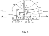
- the safety apparatus includes an upper safety clamp housing 50 and a lower slide clamp housing, chamber 52.
- the safety apparatus defines as an extension of the outlet groove 33, an I.V. tube groove 54 into which the I.V. tube fits. Extending perpendicularly from the I.V. tube groove 54 is a retainer arm aperture 56 defined in the lower slide clamp housing 52.
- a right cooperating retainer arm 58 and left cooperating retainer arm 61 Contained in the retainer arm aperture 56 are a right cooperating retainer arm 58 and left cooperating retainer arm 61 which pivot from an open or loaded position to a retaining or unloaded position in which the distance between the two retainer arms 58,61 is smaller relative to the position of the retainer arms 58,61 in the open or loaded position.
- the central portion of the retainer arm aperture 56 between the cooperating retainer arms 58,61 defines the receiving area 62 for a slide clamp.
- a release pin 63 Contained on the upper safety clamp housing 50 is a release pin 63 which extends outwardly from and is capable of reciprocating into and out of the upper safety clamp housing 50.
- the release pin 63 activates a sliding mechanism which orients the slide clamp from an occluded to an open position.
- the safety clamp 65 is capable of extending into the I.V. tube groove 54 to occlude the I.V. tube.
- the further functioning of the safety clamp 65 and release pin 63 will be described in detail below in conjunction with Figures 4, 5 and 6.
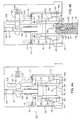
- FIG 4 a cross sectional upper view of the lower slide clamp housing 52 of the safety apparatus is seen.
- the slide clamp housing 52 is seen in an initial or preactivated condition.
- the lower slide clamp housing 52 contains the right retainer arm 58 and the left retainer arm 61. Contained on each retainer arm 58,61 is a pivot point 67 which allows the rotational pivoting of each of the retainer arms 58,61. Further contained on the end opposite the pivot point 67 of each retainer arm 58,61 is an inwardly extending retainer finger 69 which, in cooperation with the retaining finger 69 of the cooperating retainer arm, acts to retain the slide clamp as described below.
- Each retainer arm 58,61 includes biasing means which, in a preferred embodiment, can be a spring 74 which pivotally biases each retainer arm 58,61 towards the cooperating retainer arm in the retained position. However, in the preactivated or loaded position, the retainer arms 58,61 are held against the bias in the open position.
- the left retainer arm 61 further includes an upwardly protruding stepped portion 76 which extends upwardly into the upper safety clamp housing 50.
- This stepped portion 76 acts as a retaining member as will be described in detail with reference to Figure 5.
- I.V. tube groove housing 78 which defines the I.V. tube groove 54.
- the I.V. tube groove 54 is an extension of the outlet groove 33 of the pump 20.
- the I.V. tube groove 54 enables the I.V. tube to be retained in the appropriate position in both the pump 20 and the safety apparatus.
- the I.V. tube groove 54 is located centrally between the cooperating retainer arms 58,61. This acts to center the slide clamp contained on the I.V. tube between the retainer arms 58,61.
- a slide member 81 Contained distally from the I.V. tube groove 54 is a slide member 81 which is contained on a pair of cooperating slide rails 83 which allow for inward and outward reciprocal movement of the slide member 81.
- the slide member 81 includes an outwardly extending biasing means which biases the slide member 81 towards the I.V. tube groove 54.
- the outwardly extending biasing means is a spring 87.
- the slide member 81 includes cam surfaces 89 extending outwardly on each side. The cam surfaces 89 act in cooperation with the cam followers 72 of the retainer arms 58,61 to pivot the retainer arms 58,61.
- a non-obstructive sensor 85 such as an electronic eye which can be used to sense the presence of a slide clamp.
- Electronic eye 85 is positioned to sense when the slide clamp has been inserted into the slide clamp receiving area.
- the electronic eye 85 is in electronic communication with the pump operating electronics.
- the electronic eye 85 senses the fully inserted slide clamp; if a fully inserted slide clamp is not sensed, the operating electronics prevents the pump from operating.
- the non-obstructive sensor 85 will be described in further detail below in conjunction with Figure 12. Use of alternative embodiments such as a warning or an informational message will also be appreciated as possible.
- a slide shaft 92 Contained extending inwardly from the slide member 81 is a slide shaft 92.
- the slide shaft 92 is housed in a slide shaft aperture 94 defined in the lower slide clamp housing 52 and extending inwardly from the I.V. tube groove 54.
- the slide shaft 92 includes a notched portion 96 defined therein.
- a slide latch 98 is also provided housed in a slide latch aperture 101 defined in the lower slide clamp housing 52 and extending perpendicularly to the slide shaft aperture 94.
- the slide latch 98 includes a cam follower 103.
- the slide latch 98 is biased towards the slide shaft 92 by biasing means such as a spring 105.
- the slide latch 98 thus acts in conjunction with the notched portion 96 of the slide shaft 92 to retain the slide shaft 92 and thus the sliding member 81 against the outward bias of the spring 87. In the retained position, the sliding member 81 is in a loaded position while in the unretained or outward position, the sliding member 81 is in an unloaded position. It should be noted that the slide latch 98 and the notched portion 96 of the slide shaft 92 employ cooperating angled surfaces 107 which allow the slide shaft 92 to exhibit an amount of play the purpose of which will be discussed below.
- the slide clamp 109 includes a regulating aperture 110 which includes a thin occluding slot 111 and a wider non-occluding passage 112.
- the slide clamp 109 includes an access slit 113 which allows the I.V. tube 26 to be positioned into the regulating aperture 110 without requiring the slide clamp 109 to be threaded from an end of the I.V. tube 26.
- the slide clamp 109 preferably includes projections 114 which extend inwardly into the non-occluding passage 112 of the regulating aperture 110.
- the projections 114 act to maintain frictional contact against the I.V. tube 26 when the I.V. tube 26 is in the non-occluding passage 112 in an operative position while not causing an occlusion of the I.V. tube 26.
- the slide clamp 109 can be selectively positionally retained longitudinally of the I.V. tube 26 against the force of gravity yet moved longitudinally under a force in excess of the force of gravity.
- the slide clamp 109 further defines notches 115 on each oppositely facing side proximal to the non-occluding portion 112 of the regulating aperture 110. These notches 115 act in cooperation with the retaining fingers 69 of the retaining arms 58,61 to secure the slide clamp 109 in the slide clamp housing 52 when the slide clamp 109 has been inserted and the retainer arms 58,61 are unloaded.
- the distal portion of the slide clamp 109 is further defined by increased width outward projections 116. These outward projections 116 prevent inadvertent backward insertion of the slide clamp 109 into the slide clamp housing 52.
- a preferred embodiment of a slide clamp is indicated as 109' in Figure 7 with elements corresponding to those of the slide clamp 109 having the same reference number followed by a "'".
- the slide clamp 109' includes a body 117 having a leading edge 118, a trailing edge 119 and first and second oppositely facing sides 120,121.
- the slide clamp 109' includes a regulating aperture 110' having an occluded slot 111' and a non-occluding passage 112', all substantially identical to those of the slide clamp 109.
- Notches 115' are located in the first and second oppositely facing sides 120,121.
- Outer width projections 116' on the trailing edge 119 function in the same manner as the outward projections 116 on the slide clamp 109 to prevent inadvertent backward insertion of the slide clamp 109' into the slide clamp housing 52.
- An I.V. tube 26 is illustrated in ghost lines in an operative position extending through the non-occluding passage 112' of the regulating aperture 110'.
- the non-occluding passage 112' is configured to provide first, second and third I.V. tube contact points 122. Together the contact points 122 define an I.V. tube receiving space.
- the I.V. tube 26 has an outer diameter 123 equal to or slightly greater than the I.V. tube receiving space defined by the contact points 122. In this manner, the contact points 122 act to maintain frictional contact against the outer diameter 123 of the I.V. tube 26 while not causing any occlusion of the flow lumen 124 of the I. V. tube 26.
- the contact points 122 maintain sufficient frictional contact with the I.V. tube 26 that the slide clamp 109' cannot move longitudinally of an I.V. tube under the force of gravity, but requires a selected force in excess of the force of gravity to move the slide clamp 109' longitudinally of an I.V. tube 26.
- the slide clamp 109' also includes a surface pad 125.
- the surface pad 125 reflects a beam of light from the non-obstructive sensor 85, as will be discussed in more detail below with reference to Figure 12.
- the pad 125 is located in a precise selected position on the slide clamp 109' to insure proper cooperation with the non-obstructive sensor 85.
- the surface pad 125 is provided with a shiny finish (such as a No. 2 finish) to aid in reflecting a light beam transmitted by the non-obstructive sensor 85.
- the top and bottom (not shown) of the slide clamp 109' are mirror images so that slide clamp 109' can be inserted into the slide clamp housing 52 with either the top or bottom orientated upward.
- the slide clamps 109,109' are preferably injection molded from polypropylene.
- the clamps could also be made from PETG, co-polyester or DELRIN.
- the necessary characteristics of the slide clamp material are that it be moldable within close tolerances and rigid enough to withstand pressures of up to 310.275 KPa (45 psi) within the I.V. tube.
- the slide clamp material must be able to withstand EtO and gamma sterilization without impairing the functionality of the clamp.
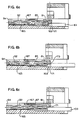
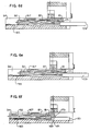
- FIG 8 illustrates in cross-section the preferred profile of the occluding slot 111'.
- the occluding slot has an I.V. tube contacting surface 126 of a length L less than the distance W between the top and bottom surfaces 127,128 of the slide clamp 109'.
- Between the top and bottom surfaces 127,128 and the I.V. contacting surface 126 are guiding surfaces 129.
- the guiding surfaces 129 constitute beveled edges between the I.V. contacting surface 126 and the top and bottom surfaces 127,128.
- the I.V. contacting surface 126 of a length L less than the distance W between the top and bottom surfaces 127,128 along with the beveled I.V.
- FIG. 10 illustrates a slide clamp wherein the I.V. tube contacting surface is a length L equal to the distance W between the top and bottom surfaces of a slide clamp, providing a large frictional surface to oppose sliding of the I.V. tube between the I.V. tube contacting surfaces.
- Figure 11 illustrates a slide clamp having an arcuate I.V. contacting surface. As seen in Figure 11, the entire arcuate surface contacts the I.V. tube, again creating a relatively large frictional surface to oppose movement of the I.V. tube 26 through the occluding slot.
- the profile illustrated in Figure 8 permits a relatively thick body 117 for durability and sufficient rigidity to maintain the I.V. tube in an occluded state, even with the I.V. tube under high internal fluid pressure, while still allowing the slide clamp to slide transverse to the I.V. tube with minimal frictional resistance.
- the I.V. contacting surface 126 has a length L of between 0.152 and 0.508 mm (.006 and .02 inches). Preferably, the length L is between 0.254 and 0.356 mm (.01 and .014 inches).
- the angle A between the I.V. tube contacting surface 126 and the top and bottom surfaces 127,128 must be sufficient so that the guiding surfaces 129 do not contact the I.V. tube 26. Preferably, the angle A is in a range of between 25°-45°, with an angle of 35° being ideal.
- acceptable slot dimensions for use with PVC tubing having a 2.59 mm (0.102 inch) inner diameter and a 0.483 mm (0.019 inch) wall thickness are as follows:
- FIG 12 illustrates a preferred embodiment of the non-obstructive sensor 85.
- the non-obstructive sensor 85 includes an optical light source 200 and an optical light sensor 202.
- the optical light source 200 emits a beam of light 204 directed onto the surface pad 125 of the I.V. clamp 109'.
- a portion 206 of the light beam 204 is reflected off the surface pad 125 and received by the optical light sensor 202.
- the optical light sensor 202 is in a first state in response to receiving a reflected light beam within a selected band width and of a selected intensity and in a second state in response to not receiving a reflected light beam within the selected intensity and band width.
- a switch 208 in electrical communication with the optical light sensor 202 disables the pump in response to the optical light sensor 202 being in the second state.
- the optical sensor 202 will not be in the second state and the pump will not function.
- the preferred embodiment of the non-obstructive sensor 85 described herein verifies that a slide clamp inserted into the clamp receiving area is compatible with the safety apparatus. Consequently, catastrophic injury to patients resulting from the use of functionally incompatible slide clamps can be prevented.
- the slide clamp 109 is shown inserted into the slide clamp housing 52.
- the end opposite the outward projections 116 is inserted into the slide clamp housing 52. This results in the non-occluding passage 112 of the regulating aperture 110 being inserted first.
- the action of the health care professional manually inserting the slide clamp 109 into the slide clamp housing 52 in conjunction with the I.V. tube groove 54 assures that, after full insertion, the I.V. tube 26 is positioned in the occluding slot 111 of the slide clamp 109.
- FIG 5 a cutaway view of the upper safety clamp housing 50 is seen.
- the position of the elements of the upper safety clamp housing 50 in Figures 5a-5f correspond to the position of the elements of the lower slide clamp housing 50 in Figures 4a-4f.
- the safety clamp housing 50 includes the generally L-shaped safety clamp 65.
- the safety clamp 65 includes an occluding member 130 which is capable of extending into the I.V. tube groove 54 and acting in cooperation with an occluding base 132 to occlude the I.V. tube 26.
- the generally L-shaped safety clamp 65 includes a pivot point 134 which allows the safety clamp 65 to alternatively pivot from an occluded state seen in Figure 5e to a non-occluding state seen in Figure 5a.
- a latching segment 136 having a latching notch 138 is defined which acts in cooperation with a safety latch 140 which will be described in detail below.
- the left retainer arm 61 includes an upwardly protruding stepped portion 76 which extends upwardly into the upper safety clamp housing 50.
- the upwardly protruding stepped portion 76 of the left retaining arm 61 is oriented in the upper safety clamp housing 50 adjacent to the safety clamp 65.
- the stepped portion 76 prevents the safety clamp 65 from fully pivoting through interference with downward protruding stepped portion 200 of safety clamp 65 while when the left retaining arm 61 is in the open position, the safety clamp 65 is allowed to fully pivot.
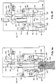
- the upper safety clamp housing 50 further includes a generally L-shaped safety latch 140.
- the safety latch 140 includes a pivot point 142 which allows the safety latch 140 to pivot from an engaged to a non-engaged position.
- the safety latch 140 and safety clamp 65 are both biased by biasing means which bias the safety clamp 65 towards the occluded position and bias the safety latch 140 towards the safety clamp 65.
- the biasing means is a spring 144 connected between a spring attachment point 146 on the upper portion of the generally L-shaped safety clamp 65 and a spring attachment point 148 on the lower portion of the generally L-shaped safety latch 140.
- the safety latch 140 includes at the end opposite the spring attachment point 148 a latching mechanism 151 which acts in cooperative latching orientation with the safety clamp latching notch 138. Additionally, the safety clamp 65 and the safety latch 140 are biased by the spring 144 such that when the safety clamp 65 is in the non-occluding state, the safety latch 140 can pivot into the engaged position to catch the latching notch 138 in the safety clamp 65 to maintain the safety clamp 65 in the non-occluding state as depicted in Figure 5c. Alternatively, when the safety clamp 65 is in the occluded state, the safety latch 140 has pivoted out of the way into the non-engaged position and is thus nonoperative so the bias of the spring 144 can maintain the safety clamp 65 in the occluded state.
- the upper safety clamp housing 50 further includes the release pin 63.
- the release pin 63 is outwardly biased by biasing means such as a spring 153.
- the release pin 63 is engaged with the safety latch by a pivot point 155 such that back and forth movement of the release pin 63 causes pivoting movement of the safety latch 140.
- the release pin 63 further includes a release arm 157 which includes a downwardly extending cam surface 159.
- the downwardly extending cam surface 159 acts cooperatively with the cam follower 103 of the slide latch 98 such that back and forth movement of the release pin 63 causes the slide latch 98 to slide.
- the safety clamp 65 Prior to loading the slide clamp 109 (as discussed, hereinafter the slide clamp 109 and 109' may be used interchangeably) into the lower slide clamp housing 52, the safety clamp 65 can be in either the occluded or non-occluding state. If in the occluded state, the left retainer arm 61 is in the open state which allows the safety clamp 65 to be fully pivoted to the non-occluding state. When pivoted to the non-occluding state, the safety latch 140 will catch and maintain the safety clamp 65 in the non-occluding state and the I.V. tube 26 can be loaded.
- the door 36 includes a stepped inlet 162.
- the stepped inlet 162 includes a first stepped portion 164 corresponding to the safety clamp 65.
- the stepped inlet 162 includes a second stepped portion 166 corresponding to the release pin 63.
- the stepped portions 164,166 are sized to assure proper functional relationship with the safety clamp 65 and the release pin 63.
- the second stepped portion 166 causes the ingress of the release pin 63 which has two effects. Initially, the release pin 63 pivots the safety latch 140 thereby releasing the safety clamp 65 and causing the safety clamp 65 to return to the occluded condition.
- the release arm 157 cam surface 159 acts in conjunction with the cam follower 103 of the slide latch 98 to force the slide latch 98 against the bias of the spring 105 thereby releasing the slide shaft 92 which causes the slide clamp 109 to move out to the non-occluding state.
- the fully closed door 36 obstructs the free pivoting of the safety clamp 65 by pressing the stepped portion 164 against the safety clamp 65. The safety clamp 65 is thereby forced into a non-occluding unlatched state.
- the slide clamp 109 allows flow of fluid through that portion of the I.V. tube 26.
- the safety clamp 65 is maintained in an open but not latched position by the door 36 thus allowing flow of fluid through that portion of the I.V. tube 26.
- the peristaltic fingers 31 are then free to provide the only occlusion or propelling motion on the contents of the I.V. tube 26.
- the door 36 When infusion is completed and the health care professional wishes to unload the I.V. tube 26, the door 36 is opened as seen in Figures 4e and 5e. Opening the door 36 removes the restriction from the safety clamp 65 causing the safety clamp 65 to bias into the occluded state. This causes an immediate prevention of non-occlusion as soon as the door 36 is opened. However, if it is desired to allow non-occluding when the door 36 is in the open position, such as for example air purging, the safety clamp 65 can be manually pressed into the open but unlatched position.
- the slide clamp 109 and I.V. tube 26 cannot be removed upon opening the door 36. Rather, prior to removing the slide clamp 109 and the I.V. tube 26 the health care professional is required to again insert the slide clamp 109 into the slide clamp housing 52.
- the safety clamp 65 can be freely pivoted into an open and latched position which then and only then allows for the health care professional to remove the occluded I.V. tube 26.
- the slide shaft aperture 94 includes an upwardly biasing means which in a preferred embodiment is spring member 165 contained in the distal portion of the slide shaft aperture 94.
- the aperture defines a retaining wall 167 which allows the slide shaft 92 to freely slide but which provides a stop for the spring 87 to cause the forward bias of the slide shaft 92.
- the slide member 81 includes a sized portion 169 on its lower periphery which is sized to accept a slide clamp 109. Additionally, extending upwardly from the sized portion is a incline portion 171 which guides the slide clamp 109 into the sized portion 169.
- the slide rail 83 includes a stepped portion 173 best seen in Figure 6f.
- the slide rail stepped portion 173 acts in conjunction with the slide member 81 to retain the slide member 81 in the rearwardly biased or loaded position.
- a slide clamp 109 In order for the slide member 81 to become fully outwardly extended or unloaded, it is necessary for a slide clamp 109 to be inserted into the device which causes the sliding member 81 to move upwardly which allows the slide member 81 to extend past the stepped portion 173 and become unloaded.
- the amount of play between the fully inserted position of the slide member 81 and the position of the slide member 81 when caught on the slide rail 83 stepped portion 173 is about equivalent to the amount of play allowed by the tapered slide latch 98.
- Figure 6a when the door 36 has been closed without the presence of a slide clamp 109, thereby activating the release pin 63, the slide member 81 initially attempts to bias forward but is retained by the slide rail stepped portion 173. This is to be contrasted with Figure 6f, in which the slide member 81 is retained by the slide latch 98 when the slide clamp 109 is inserted and the release pin 63 has not been activated.
- peristaltic pump having pressure fingers
- a rotary-type peristaltic pump can be used instead of the peristaltic pump having pressure fingers.
Landscapes
- Health & Medical Sciences (AREA)
- Heart & Thoracic Surgery (AREA)
- Pulmonology (AREA)
- Engineering & Computer Science (AREA)
- Anesthesiology (AREA)
- Biomedical Technology (AREA)
- Hematology (AREA)
- Life Sciences & Earth Sciences (AREA)
- Animal Behavior & Ethology (AREA)
- General Health & Medical Sciences (AREA)
- Public Health (AREA)
- Veterinary Medicine (AREA)
- Infusion, Injection, And Reservoir Apparatuses (AREA)
- Reciprocating Pumps (AREA)
- External Artificial Organs (AREA)
- Media Introduction/Drainage Providing Device (AREA)
Claims (28)
- Sicherheitsvorrichtung zur Verwendung mit einer intravenösen Verabreichungspumpe, wobei die Sicherheitsvorrichtung folgendes aufweist: einen Gleitklemmenaufnahmebereich (62) zur Aufnahme einer Gleitklemme (109, 109'), die an einem i.v. Schlauch (26) enthalten ist und diesen verschließt; und einen Festlegearm (58, 61), der um den Gleitklemmenaufnahmebereich herum enthalten ist, um die Gleitklemme in dem Gleitklemmenaufnahmebereich festzulegen;
gekennzeichnet durch ein belastetes Gleitelement (81), das in dem Gleitklemmenaufnahmebereich angeordnet und imstande ist, aus der belasteten Position in eine unbelastete Position zu gleiten, um die Gleitklemme (109, 109') in eine nichtverschließende Position zu drängen; eine Vielzahl von Festlegearmen (58, 61), wobei jeder Arm in einer ersten Position ist, in der im Gebrauch die Arme außer Eingriff mit der Gleitklemme sind, und in eine zweite Position bewegbar ist, in der die Arme mit der Gleitklemme in Eingriff gelangen, um die Gleitklemme in dem Aufnahmebereich (62) festzulegen; und einen Lösestift (63), der dem Gleitelement und den Festlegearmen damit zusammenwirkend zugeordnet ist und der bei Aktivierung (i) das Gleitelement (81) entlastet, so daß das Gleitelement veranlaßt wird, die Gleitklemme in die nichtverschließende Position an dem i.v. Schlauch zu drängen, und (ii) bewirkt, daß die Festlegearme (58, 61) sich in die zweite Position bewegen, um die nichtverschließende Gleitklemme in dem Gleitklemmenaufnahmebereich festzulegen. - Vorrichtung nach Anspruch 1, wobei das Gleitelement (81) einen Exzenterbereich (89) aufweist und die Festlegearme (58, 61) zusammenwirkende Exzenterfolgerbereiche (72) aufweisen, so daß, wenn das Gleitelement belastet ist, die Festlegearme ebenfalls belastet werden.
- Vorrichtung nach Anspruch 1 oder 2, die ferner eine verschließende vorgespannte Sicherheitsklemme (65) aufweist, die imstande ist, den i.v. Schlauch (26) zu verschließen, wenn die eingeführte Gleitklemme (109, 109') in der nichtverschließenden Position ist.
- Intravenöse Verabreichungspumpe, die folgendes aufweist: die Sicherheitsvorrichtung nach einem der vorhergehenden Ansprüche und ein Gehäuse (20), das enthält: Betätigungsmechanismen und Elektronik der intravenösen Verabreichungspumpe; eine Tür (36), die mit dem Gehäuse schwenkbar verbunden ist; und eine i.v. Schlauchnut (29, 33), die in dem Gehäuse definiert ist, wobei die i.v. Schlauchnut betriebsmäßig über einem peristaltischen Bewegungsmechanismus derart positioniert ist, daß dann, wenn der i.v. Schlauch (26) in die i.v. Schlauchnut eingelegt ist, auf den i.v. Schlauch eine peristaltische Pumpwirkung aufgebracht werden kann; wobei der Gleitklemmenaufnahmebereich (62) an der i.v. Schlauchnut enthalten ist und das Gleitelement (81) in die unbelastete Position nach außen vorgespannt und in dem Aufnahmebereich enthalten ist und das Gleitelement (81) beim Einführen einer verschlossenen Gleitklemme in den Gleitklemmenaufnahmebereich belastet wird; wobei die Festlegearme (58, 61) nach innen vorgespannt und aus einer belasteten in eine unbelastete Position schwenkbar sind, so daß die Festlegearme in ihrer unbelasteten Position imstande sind, die Gleitklemme in dem Aufnahmebereich festzulegen; und wobei der Lösestift (63) der Tür (36) damit zusammenwirkend zugeordnet ist, so daß bei Aktivierung des Lösestifts durch Schließen der Tür (36) die Festlegearme (58, 61) entlastet werden, um die Gleitklemme (109, 109') teilweise in dem Aufnahmebereich (62) festzulegen.
- Pumpe nach Anspruch 4 in Abhängigkeit von Anspruch 3, wobei die Sicherheitsklemme (65) wirksam ist, um den i.v. Schlauch zu verschließen, wenn die Tür (36) geöffnet ist und die eingeführte Gleitklemme (109, 109') in der nichtverschließenden Position ist.
- Vorrichtung zum Verhindern des freien Durchflusses während des Einsetzens eines i.v. Schlauchs in eine peristaltische Pumpe, die eine Sicherheitsvorrichtung nach einem der Ansprüche 1 bis 3 und eine Schlauchnut (29, 33) aufweist, in der der i.v. Schlauch (26) positionierbar ist, wobei die Festlegearme (58, 61) dem Gleitelement (81) betriebsmäßig zugeordnet sind, so daß dann, wenn die verschlossene Gleitklemme (109, 109') in dem Gleitklemmenaufnahmebereich (62) ist, die Festlegearme in einer belasteten, aber nichtfestlegenden Position sind.
- Vorrichtung oder Pumpe nach einem der vorhergehenden Ansprüche in Kombination mit einer Gleitklemme (109, 109'), die folgendes aufweist:einen Körper, der eine obere und eine untere Oberfläche (127, 128) hat, die voneinander weg weisen; undeine Regulieröffnung (110, 110'), die von einer inneren Umfangswand in dem Körper definiert ist, die sich quer zwischen der oberen und der untere Oberfläche erstreckt, wobei die Regulieröffnung einen verschließenden Schlitz (111, 111') und einen nichtverschließenden Durchgang (112, 112') hat, wobei ein i.v. Schlauch (26), der in einer Betriebsposition ist, sich durch die Regulieröffnung erstreckt und quer zu seiner Länge zwischen dem verschließenden Schlitz und dem nichtverschließenden Durchgang gleitbar ist, so daß ein Lumen (124) des i.v. Schlauchs in der Betriebsposition selektiv verschlossen oder nicht verschlossen werden kann, indem der i.v. Schlauch zwischen dem verschließenden Schlitz und dem nichtverschließenden Durchgang gleitbewegt wird, wobei die Umfangswand, im Querschnitt gesehen, eine im wesentlichen flache den i.v. Schlauch berührende Oberfläche (126) einer Länge (L) hat, die kleiner als die Distanz (W) zwischen der oberen und der unteren Oberfläche ist, um Reibung zwischen der den i.v. Schlauch berührenden Oberfläche und dem i.v. Schlauch in der Betriebsposition zu minimieren, während der i.v. Schlauch zwischen dem verschließenden Schlitz und dem nichtverschließenden Durchgang gleitbewegt wird.
- Vorrichtung oder Pumpe nach Anspruch 7, wobei die innere Umfangswand, im Querschnitt gesehen, ferner Führungsoberflächen (129) zwischen der den i.v. Schlauch berührenden Oberfläche (126) und der oberen und der unteren Oberfläche (127, 128) aufweist.
- Vorrichtung oder Pumpe nach Anspruch 8, wobei die Führungsoberflächen (129) abgeschrägte Ränder zwischen der den i.v. Schlauch berührenden Oberfläche (126) und der oberen und der unteren Oberfläche (127, 128) aufweisen.
- Vorrichtung oder Pumpe nach Anspruch 9, wobei die den i.v. Schlauch berührende Oberfläche (126) ca. 0,254 mm (0,01 inches) breit ist und die abgeschrägten Ränder (129) unter einem Winkel von ca. 35° zu der den i.v. Schlauch berührenden Oberfläche sind.
- Vorrichtung oder Pumpe nach einem der Ansprüche 7 bis 10, wobei die den i.v. Schlauch berührende Oberfläche (126) im Bereich zwischen 0,152 und 0,508 mm (0,006 inches und 0,02 inches) breit ist.
- Vorrichtung oder Pumpe nach Anspruch 9, wobei die abgeschrägten Ränder (129) unter einem Winkel von mehr als 25° zu der den i.v. Schlauch berührenden Oberfläche (126) sind.
- Vorrichtung oder Pumpe nach einem der Ansprüche 7 bis 12, wobei der Körper ferner einen vorderen und einen hinteren Rand (118, 119) aufweist, die voneinander weg weisen und die jeweils eine ausgewählte Breite haben, wobei die Breite des vorderen Rands (118) kleiner als die Breite des hinteren Rands (119) ist, um eine ausgewählte Orientierung der Gleitklemme vor dem Einführen der Gleitklemme in den Gleitklemmenaufnahmebereich (62) zu erleichtern.
- Vorrichtung oder Pumpe nach einem der Ansprüche 7 bis 13, wobei der Körper ferner eine erste und eine zweite Längsseite (120, 121) aufweist, die voneinander weg weisen, wobei jede der Seiten eine Kerbe (115, 115') zur Aufnahme eines jeweiligen Festlegearms (58, 61) hat, um eine Längsbewegung der Gleitklemme (109, 109') zu verhindern.
- Vorrichtung oder Pumpe nach einem der Ansprüche 7 bis 14, die ferner eine Einrichtung (122) an der Gleitklemme (109, 109') aufweist, um ein Gleiten der Gleitklemme längs des i.v. Schlauchs, wenn sich dieser in einer Betriebsposition durch den nichtverschließenden Durchgang (112, 112') erstreckt, ausschließlich durch Schwerkraft zu verhindern, wobei die Gleitverhinderungseinrichtung (122) eine Bewegung der Gleitklemme längs des i.v. Schlauchs bei Aufbringen einer vorbestimmten Kraft, die größer als die Schwerkraft ist, gestattet.
- Vorrichtung oder Pumpe nach einem der Ansprüche 1 bis 6 in Kombination mit einer Gleitklemme (109, 109'), die einen Körper aufweist, der eine obere und eine untere Oberfläche (127, 128) hat, die voneinander weg weisen;
eine Regulieröffnung (110, 110'), die einen verschließenden Schlitz (111, 111') und einen nichtverschließenden Durchgang (112, 112') definiert, wobei ein i.v. Schlauch (26), der in einer Betriebsposition ist, sich durch die Öffnung erstreckt und quer zu seiner Länge zwischen dem verschließenden Schlitz und dem nichtverschließenden Durchgang gleitbar ist, so daß ein Lumen (124) des i.v. Schlauchs in der Betriebsposition selektiv verschlossen oder nicht verschlossen werden kann; und
eine Einrichtung (122) an der Gleitklemme (109, 109'), um ein Gleiten der Gleitklemme längs des i.v. Schlauchs, wenn sich dieser in der Betriebsposition durch den nichtverschließenden Durchgang erstreckt, ausschließlich durch Schwerkraft zu verhindern, wobei die Gleitverhinderungseinrichtung (122) eine Bewegung der Gleitklemme längs des i.v. Schlauchs bei Aufbringen einer vorbestimmten Kraft, die größer als die Schwerkraft ist, gestattet. - Vorrichtung oder Pumpe nach Anspruch 15 oder 16, wobei die Gleitverhinderungseinrichtung (122) einen nichtverschließenden Durchgang (112, 112') aufweist, der wenigstens zwei Kontaktpunkte (122) hat, die eine ausgewählte Distanz zwischen sich haben, wobei der i.v. Schlauch, der sich durch die Öffnung erstreckt, einen Außendurchmesser hat, der nicht kleiner als die ausgewählte Distanz ist.
- Vorrichtung oder Pumpe nach einem der vorhergehenden Ansprüche in Kombination mit einer Gleitklemme (109, 109'), die eine Einrichtung (125) an der Gleitklemme (109, 109') aufweist, um eine automatische Identifikation der Klemme zu erleichtern.
- Vorrichtung oder Pumpe nach Anspruch 18, wobei die automatische Identifikationseinrichtung (125) einen Oberflächenbereich aufweist, wobei der Oberflächenbereich einen ausgewählten Anteil (206) eines darauf gerichteten Lichtstrahls (204) reflektiert, so daß ein den reflektierten Strahl empfangender optischer Sensor (202) die Gleitklemme identifizieren kann.
- Vorrichtung oder Pumpe nach einem der Ansprüche 1 bis 6 in Kombination mit einer Gleitklemme (109, 109'), die folgendes aufweist:einen Körper;eine Einrichtung (110, 110') an dem Körper, die eine äußere Oberfläche eines i.v. Schlauchs (26) in einer Betriebsposition festhaltend aufnimmt, wobei der i.v. Schlauch ein Durchflußlumen (124) hat;eine Einrichtung (112, 112') an dem Körper zum Kollabieren einer äußeren Oberfläche des i.v. Schlauchs in einer Betriebsposition in der festhaltend aufnehmenden Einrichtung (110, 110'), so daß das Durchflußlumen des i.v. Schlauchs selektiv verschlossen und nicht verschlossen wird; undeine Einrichtung (125) an dem Körper, um die automatische Identifikation der Klemme (109, 109') zu erleichtern.
- Vorrichtung oder Pumpe nach Anspruch 20, wobei die automatische Identifikationseinrichtung (125) ein Oberflächenansatzelement aufweist, wobei das Oberflächenansatzelement einen ausgewählten Anteil eines darauf gerichteten Lichtstrahls (206) reflektiert, so daß eine Einrichtung (200, 202) zur optischen Identifikation die Gleitklemme (109, 109') auf der Basis des reflektierten ausgewählten Anteils des Lichtstrahls identifizieren kann.
- Vorrichtung oder Pumpe nach Anspruch 21 in Kombination mit einer Einrichtung (200, 202) zur optischen Identifikation, wobei die Einrichtung zur optischen Identifikation folgendes aufweist:eine Lampe (200) zum Aussenden eines ausgewählten Lichtstrahls (204), wobei der Lichtstrahl auf das Oberflächenansatzelement (125) gerichtet wird, wobei das Oberflächenansatzelement einen Anteil des Lichtstrahls absorbiert und einen ausgewählten Anteil (206) des Lichtstrahls reflektiert;einen optischen Sensor (202) zum Empfang des reflektierten ausgewählten Anteils (206) des Lichtstrahls, wobei der optische Sensor in Abhängigkeit von dem Empfang des ausgewählten Anteils des Lichtstrahls in einem ersten Zustand ist und in Abhängigkeit von dem Nichtempfang des ausgewählten Anteils eines Lichtstrahls in einem zweiten Zustand ist; undeine Einrichtung, die dem optischen Sensor (202) betriebsmäßig zugeordnet ist, um anzuzeigen, daß der optische Sensor in dem ersten oder dem zweiten Zustand ist.
- Vorrichtung oder Pumpe nach einem der vorhergehenden Ansprüche in Kombination mit einer Gleitklemme (109, 109'), die an dem i.v. Schlauch (26) enthalten ist und den Schlauch verschließt, wobei der i.v. Schlauch (26) an einer oder der Pumpe (20) angebracht ist, wobei die Sicherheitsvorrichtung einen nichtblockierenden Sensor (85) in dem Klemmenaufnahmebereich (62) aufweist, wobei der nichtblockierende Sensor in Abhängigkeit von der Anwesenheit der Klemme (109, 109') in einer ausgewählten Position in dem Gleitklemmenaufnahmebereich (62) in einem ersten Zustand ist und in Abhängigkeit von der Abwesenheit der Gleitklemme von der ausgewählten Position in einem zweiten Zustand ist; und
eine Einrichtung, die dem nichtblockierenden Sensor (85) betriebsmäßig zugeordnet ist, um die Pumpe (20) in Abhängigkeit davon, daß der nichtblockierende Sensor in dem zweiten Zustand ist, zu desaktivieren. - Vorrichtung oder Pumpe nach Anspruch 23, wobei die Klemme (109, 109') eine Gleitklemme aufweist, die eine Regulieröffnung (110, 110') hat, wobei die Regulieröffnung einen verschließenden Schlitz (111, 111') und einen nichtverschließenden Durchgang (112, 112') hat, wobei der i.v. Schlauch, der in einer Betriebsposition ist, sich durch die Regulieröffnung erstreckt und quer zu seiner Länge zwischen dem verschließenden Schlitz und dem nichtverschließenden Durchgang gleitbar ist, so daß ein Lumen (124) eines i.v. Schlauchs in der Betriebsposition selektiv verschlossen oder nicht verschlossen werden kann, indem der i.v. Schlauch zwischen dem verschließenden Schlitz und dem nichtverschließenden Durchgang gleitbewegt wird.
- Vorrichtung oder Pumpe nach Anspruch 23 oder 24, wobei der nichtblockierende Sensor ein magisches Auge (85) aufweist.
- Vorrichtung oder Pumpe nach Anspruch 23, 24 oder 25, wobei der nichtblockierende Sensor folgendes aufweist:ein Ansatzelement (125) an der Klemme (109, 109') zum Reflektieren eines ausgewählten Anteils (206) eines Lichtstrahls (204);eine Lichtquelle (200) in dem Klemmenaufnahmebereich (62), die einen Lichtstrahl (204) auf das Ansatzelement (125) richtet; undeinen optischen Sensor (202) zum Empfang des ausgewählten Anteils (206) des von dem Ansatzelement weg reflektierten Lichtstrahls, wobei der optische Sensor in Abhängigkeit von dem Empfang des ausgewählten Anteils eines Lichtstrahls in einem ersten Zustand ist und in Abhängigkeit von dem Nichtempfang des ausgewählten Anteils eines Lichtstrahls in einem zweiten Zustand ist.
- Vorrichtung oder Pumpe nach Anspruch 23, 24, 25 oder 26, wobei der nichtblockierende Sensor (85) ferner eine Einrichtung zum Bestimmen der Kompatibilität der Gleitklemme (109, 109') mit dem Sensor (85) aufweist, wobei der nichtblockierende Sensor in einem ersten Zustand ist, wenn die Klemme mit der Sicherheitsvorrichtung kompatibel ist, und in einem zweiten Zustand ist, wenn die Klemme mit der Sicherheitsvorrichtung nicht kompatibel ist.
- Vorrichtung oder Pumpe nach einem der Ansprüche 23 bis 27, wobei die Pumpe eine peristaltische Pumpe (20) aufweist.
Priority Applications (4)
| Application Number | Priority Date | Filing Date | Title |
|---|---|---|---|
| EP96200502A EP0718006B1 (de) | 1991-09-26 | 1992-09-25 | Gleitklemme für einen Schlauch mit Gleitsperre |
| EP96200504A EP0718008B2 (de) | 1991-09-26 | 1992-09-25 | Sicherheitsvorrichtung für eine Infusionspumpe mit einem berührungsloser Sensor zum Nachweis einer Klemme |
| EP96200503A EP0718007B1 (de) | 1991-09-26 | 1992-09-25 | Gleitklemme für einen Schlauch mit Vorrichtung zur Reibungsverminderung |
| EP98202761A EP0876825B1 (de) | 1991-09-26 | 1992-09-25 | Gleitklemme für eine Schlauch mit Gleitsperre |
Applications Claiming Priority (5)
| Application Number | Priority Date | Filing Date | Title |
|---|---|---|---|
| US76575591A | 1991-09-26 | 1991-09-26 | |
| US765755 | 1991-09-26 | ||
| US07/884,498 US5290239A (en) | 1991-09-26 | 1992-05-15 | Intravenous tube safety apparatus |
| US884498 | 1992-05-15 | ||
| PCT/US1992/008212 WO1993005829A1 (en) | 1991-09-26 | 1992-09-25 | Intravenous tube safety apparatus |
Related Child Applications (6)
| Application Number | Title | Priority Date | Filing Date |
|---|---|---|---|
| EP96200503A Division EP0718007B1 (de) | 1991-09-26 | 1992-09-25 | Gleitklemme für einen Schlauch mit Vorrichtung zur Reibungsverminderung |
| EP96200502A Division EP0718006B1 (de) | 1991-09-26 | 1992-09-25 | Gleitklemme für einen Schlauch mit Gleitsperre |
| EP96200504A Division EP0718008B2 (de) | 1991-09-26 | 1992-09-25 | Sicherheitsvorrichtung für eine Infusionspumpe mit einem berührungsloser Sensor zum Nachweis einer Klemme |
| EP96200503.9 Division-Into | 1996-02-27 | ||
| EP96200504.7 Division-Into | 1996-02-27 | ||
| EP96200502.1 Division-Into | 1996-02-27 |
Publications (3)
| Publication Number | Publication Date |
|---|---|
| EP0563351A1 EP0563351A1 (de) | 1993-10-06 |
| EP0563351A4 EP0563351A4 (de) | 1994-03-24 |
| EP0563351B1 true EP0563351B1 (de) | 1997-12-03 |
Family
ID=27117646
Family Applications (5)
| Application Number | Title | Priority Date | Filing Date |
|---|---|---|---|
| EP96200503A Expired - Lifetime EP0718007B1 (de) | 1991-09-26 | 1992-09-25 | Gleitklemme für einen Schlauch mit Vorrichtung zur Reibungsverminderung |
| EP98202761A Expired - Lifetime EP0876825B1 (de) | 1991-09-26 | 1992-09-25 | Gleitklemme für eine Schlauch mit Gleitsperre |
| EP96200502A Expired - Lifetime EP0718006B1 (de) | 1991-09-26 | 1992-09-25 | Gleitklemme für einen Schlauch mit Gleitsperre |
| EP96200504A Expired - Lifetime EP0718008B2 (de) | 1991-09-26 | 1992-09-25 | Sicherheitsvorrichtung für eine Infusionspumpe mit einem berührungsloser Sensor zum Nachweis einer Klemme |
| EP92921177A Expired - Lifetime EP0563351B1 (de) | 1991-09-26 | 1992-09-25 | Sicherheitseinrichtung für intravenösen schlauch |
Family Applications Before (4)
| Application Number | Title | Priority Date | Filing Date |
|---|---|---|---|
| EP96200503A Expired - Lifetime EP0718007B1 (de) | 1991-09-26 | 1992-09-25 | Gleitklemme für einen Schlauch mit Vorrichtung zur Reibungsverminderung |
| EP98202761A Expired - Lifetime EP0876825B1 (de) | 1991-09-26 | 1992-09-25 | Gleitklemme für eine Schlauch mit Gleitsperre |
| EP96200502A Expired - Lifetime EP0718006B1 (de) | 1991-09-26 | 1992-09-25 | Gleitklemme für einen Schlauch mit Gleitsperre |
| EP96200504A Expired - Lifetime EP0718008B2 (de) | 1991-09-26 | 1992-09-25 | Sicherheitsvorrichtung für eine Infusionspumpe mit einem berührungsloser Sensor zum Nachweis einer Klemme |
Country Status (7)
| Country | Link |
|---|---|
| US (2) | US5290239A (de) |
| EP (5) | EP0718007B1 (de) |
| JP (2) | JP3508024B2 (de) |
| AU (2) | AU656035B2 (de) |
| CA (4) | CA2095857C (de) |
| DE (5) | DE69226663T2 (de) |
| WO (1) | WO1993005829A1 (de) |
Cited By (9)
| Publication number | Priority date | Publication date | Assignee | Title |
|---|---|---|---|---|
| US7722573B2 (en) | 2006-03-02 | 2010-05-25 | Covidien Ag | Pumping apparatus with secure loading features |
| US7722562B2 (en) | 2006-03-02 | 2010-05-25 | Tyco Healthcare Group Lp | Pump set with safety interlock |
| US7758551B2 (en) | 2006-03-02 | 2010-07-20 | Covidien Ag | Pump set with secure loading features |
| US7763005B2 (en) | 2006-03-02 | 2010-07-27 | Covidien Ag | Method for using a pump set having secure loading features |
| US7846131B2 (en) | 2005-09-30 | 2010-12-07 | Covidien Ag | Administration feeding set and flow control apparatus with secure loading features |
| US7927304B2 (en) | 2006-03-02 | 2011-04-19 | Tyco Healthcare Group Lp | Enteral feeding pump and feeding set therefor |
| US8021336B2 (en) | 2007-01-05 | 2011-09-20 | Tyco Healthcare Group Lp | Pump set for administering fluid with secure loading features and manufacture of component therefor |
| US8053721B2 (en) | 2006-12-11 | 2011-11-08 | Tyco Healthcare Group Lp | Pump set and pump with electromagnetic radiation operated interlock |
| US8154274B2 (en) | 2010-05-11 | 2012-04-10 | Tyco Healthcare Group Lp | Safety interlock |
Families Citing this family (116)
| Publication number | Priority date | Publication date | Assignee | Title |
|---|---|---|---|---|
| US5772637A (en) * | 1995-06-07 | 1998-06-30 | Deka Products Limited Partnership | Intravenous-line flow-control system |
| US5853397A (en) * | 1993-12-13 | 1998-12-29 | Migada, Inc. | Medical infusion apparatus including safety valve |
| US5401256A (en) * | 1994-01-14 | 1995-03-28 | Minnesota Mining And Manufacturing Company | Flexible clamp for use in IV tubing set |
| US5562615A (en) * | 1994-02-28 | 1996-10-08 | Corpak, Inc. | Free flow detector for an enternal feeding pump |
| US5658133A (en) * | 1994-03-09 | 1997-08-19 | Baxter International Inc. | Pump chamber back pressure dissipation apparatus and method |
| US5482446A (en) * | 1994-03-09 | 1996-01-09 | Baxter International Inc. | Ambulatory infusion pump |
| US5453098A (en) * | 1994-05-09 | 1995-09-26 | Imed Corporation | Two step IV fluid flow stop |
| US5601420A (en) * | 1994-09-12 | 1997-02-11 | Ivac Medical Systems, Inc. | Interlock, latching, and retaining mechanism for an infusion pump |
| US5505709A (en) * | 1994-09-15 | 1996-04-09 | Minimed, Inc., A Delaware Corporation | Mated infusion pump and syringe |
| US5567120A (en) * | 1994-10-13 | 1996-10-22 | Sigma International | Electronic infusion device and novel roller clamp holden therefor |
| US5904668A (en) | 1995-03-06 | 1999-05-18 | Sabratek Corporation | Cassette for an infusion pump |
| GB2305370B (en) * | 1995-09-19 | 1997-10-29 | Asahi Medical Co | Device for depletion of leukocytes |
| US5967484A (en) * | 1995-12-21 | 1999-10-19 | Alaris Medical Systems, Inc. | Intravenous tube occluder |
| US5833213A (en) * | 1995-12-29 | 1998-11-10 | Rymed Technologies, Inc. | Multiple dose drug vial adapter for use with a vial having a pierceable septum and a needleless syringe |
| US5788215A (en) * | 1995-12-29 | 1998-08-04 | Rymed Technologies | Medical intravenous administration line connectors having a luer or pressure activated valve |
| US5954313A (en) * | 1995-12-29 | 1999-09-21 | Rymed Technologies, Inc. | Medical intravenous administration line connectors having a luer activated valve |
| AU723365B2 (en) * | 1996-04-10 | 2000-08-24 | Baxter International Inc. | An infusion pump with a tube present sensor |
| GB9607471D0 (en) * | 1996-04-10 | 1996-06-12 | Baxter Int | Volumetric infusion pump |
| GB2338757B (en) * | 1996-04-10 | 2000-05-31 | Baxter Int | Volumetric infusion pump |
| AU725739B2 (en) * | 1996-04-10 | 2000-10-19 | Baxter International Inc. | Method of detecting a misload of a tube into a volumetric infusion pump |
| AU736366B2 (en) * | 1996-04-10 | 2001-07-26 | Baxter International Inc. | Automatic loading apparatus for volumetric infusion pump |
| FR2748310A1 (fr) * | 1996-05-03 | 1997-11-07 | Debiotech Sa | Dispositif d'obturation par pincement d'un tube souple |
| US5853386A (en) | 1996-07-25 | 1998-12-29 | Alaris Medical Systems, Inc. | Infusion device with disposable elements |
| US6702789B1 (en) | 1997-03-11 | 2004-03-09 | Alcove Medical, Inc. | Catheter having insertion control mechanism and anti-bunching mechanism |
| US6261262B1 (en) | 1997-06-12 | 2001-07-17 | Abbott Laboratories | Pump with anti-free flow feature |
| US6877713B1 (en) | 1999-07-20 | 2005-04-12 | Deka Products Limited Partnership | Tube occluder and method for occluding collapsible tubes |
| DE19944343A1 (de) | 1999-09-16 | 2001-04-12 | Fresenius Ag | Ventil |
| US6592519B1 (en) * | 2000-04-28 | 2003-07-15 | Medtronic, Inc. | Smart microfluidic device with universal coating |
| WO2003006101A2 (en) * | 2001-07-10 | 2003-01-23 | Medrad, Inc. | Devices, systems and method for infusion of fluids |
| US6722865B2 (en) | 2001-09-07 | 2004-04-20 | Terumorcardiovascular Systems Corporation | Universal tube clamp assembly |
| EP1446175B1 (de) * | 2001-11-15 | 2006-11-08 | Arcomed Ag | Infusionspumpe |
| ITMI20020359A1 (it) | 2002-02-22 | 2003-08-22 | Gambro Lundia Ab | Metodo di controllo dell'operativita' di un organo di interdizione del flusso e dispositivo di arresto del flusso per un circuito extracorpo |
| US7018361B2 (en) | 2002-06-14 | 2006-03-28 | Baxter International Inc. | Infusion pump |
| US7267661B2 (en) | 2002-06-17 | 2007-09-11 | Iradimed Corporation | Non-magnetic medical infusion device |
| US7553295B2 (en) * | 2002-06-17 | 2009-06-30 | Iradimed Corporation | Liquid infusion apparatus |
| SE526008C2 (sv) | 2002-10-10 | 2005-06-14 | Medical Vision Res & Dev Ab | Medicinskt-tekniskt identifieringsdon |
| US20040088189A1 (en) * | 2002-11-06 | 2004-05-06 | Veome Edmond A. | System and method for monitoring , reporting, managing and administering the treatment of a blood component |
| DE10312272A1 (de) * | 2003-03-19 | 2004-09-30 | Justus-Liebig-Universität Giessen | Vorrichtung und Messverfahren zur Testung der cerebralen autoregulativen Kapazität höherer Säuger |
| IL157981A (en) | 2003-09-17 | 2014-01-30 | Elcam Medical Agricultural Cooperative Ass Ltd | Auto injector |
| US6840492B1 (en) | 2003-11-21 | 2005-01-11 | Alaris Medical Systems, Inc. | Slide clamp |
| IL160891A0 (en) | 2004-03-16 | 2004-08-31 | Auto-mix needle | |
| US20050277873A1 (en) | 2004-05-27 | 2005-12-15 | Janice Stewart | Identification information recognition system for a medical device |
| US7927313B2 (en) * | 2004-05-27 | 2011-04-19 | Baxter International Inc. | Medical device configuration based on recognition of identification information |
| JP4754917B2 (ja) * | 2004-10-19 | 2011-08-24 | テルモ株式会社 | 輸液装置 |
| US7976518B2 (en) | 2005-01-13 | 2011-07-12 | Corpak Medsystems, Inc. | Tubing assembly and signal generator placement control device and method for use with catheter guidance systems |
| CN101273361A (zh) * | 2005-02-01 | 2008-09-24 | 巴克斯特国际公司 | 输液传输系统 |
| US20060264935A1 (en) * | 2005-05-04 | 2006-11-23 | White Patrick M | Orthopedic stabilization device |
| US20070095941A1 (en) * | 2005-11-03 | 2007-05-03 | Gorres Geoffrey H | Scent dispensing apparatus |
| US10537671B2 (en) | 2006-04-14 | 2020-01-21 | Deka Products Limited Partnership | Automated control mechanisms in a hemodialysis apparatus |
| MX2008013266A (es) | 2006-04-14 | 2008-10-27 | Deka Products Lp | Sistemas, dispositivos y metodos para bombeo de fluido, intercambio de calor, deteccion termica y deteccion de conductividad. |
| US7611498B2 (en) * | 2006-05-18 | 2009-11-03 | Codan Holding Gmbh | Arrangement for the coupling of an intravenous tube with infusion pump |
| FR2908176B1 (fr) | 2006-11-08 | 2008-12-19 | Fresenius Vial Soc Par Actions | Dispositif de controle de l'ouverture ou la fermeture d'une pince dans une pompe volumetrique |
| EP2101846B1 (de) | 2006-12-22 | 2019-08-28 | Mondiale Technologies Limited | Strömungsregler |
| US8491184B2 (en) | 2007-02-27 | 2013-07-23 | Deka Products Limited Partnership | Sensor apparatus systems, devices and methods |
| US8042563B2 (en) | 2007-02-27 | 2011-10-25 | Deka Products Limited Partnership | Cassette system integrated apparatus |
| US8409441B2 (en) | 2007-02-27 | 2013-04-02 | Deka Products Limited Partnership | Blood treatment systems and methods |
| US9028691B2 (en) | 2007-02-27 | 2015-05-12 | Deka Products Limited Partnership | Blood circuit assembly for a hemodialysis system |
| US8562834B2 (en) | 2007-02-27 | 2013-10-22 | Deka Products Limited Partnership | Modular assembly for a portable hemodialysis system |
| US20080253911A1 (en) | 2007-02-27 | 2008-10-16 | Deka Products Limited Partnership | Pumping Cassette |
| US20090107335A1 (en) | 2007-02-27 | 2009-04-30 | Deka Products Limited Partnership | Air trap for a medical infusion device |
| US8357298B2 (en) | 2007-02-27 | 2013-01-22 | Deka Products Limited Partnership | Hemodialysis systems and methods |
| KR102228428B1 (ko) | 2007-02-27 | 2021-03-16 | 데카 프로덕츠 리미티드 파트너쉽 | 혈액투석 시스템 |
| US8393690B2 (en) | 2007-02-27 | 2013-03-12 | Deka Products Limited Partnership | Enclosure for a portable hemodialysis system |
| US8425471B2 (en) | 2007-02-27 | 2013-04-23 | Deka Products Limited Partnership | Reagent supply for a hemodialysis system |
| US8025645B2 (en) | 2007-05-25 | 2011-09-27 | Medical Components, Inc. | Guard for flexible tubing clamp and method of using same |
| US8105282B2 (en) | 2007-07-13 | 2012-01-31 | Iradimed Corporation | System and method for communication with an infusion device |
| US8062008B2 (en) * | 2007-09-27 | 2011-11-22 | Curlin Medical Inc. | Peristaltic pump and removable cassette therefor |
| US8771508B2 (en) * | 2008-08-27 | 2014-07-08 | Deka Products Limited Partnership | Dialyzer cartridge mounting arrangement for a hemodialysis system |
| EP2217301A2 (de) * | 2007-10-12 | 2010-08-18 | DEKA Products Limited Partnership | Systeme, vorrichtungen und verfahren für kardiopulmonale behandlung und verfahren |
| US8863772B2 (en) * | 2008-08-27 | 2014-10-21 | Deka Products Limited Partnership | Occluder for a medical infusion system |
| EP4336042A3 (de) * | 2008-01-23 | 2024-05-15 | DEKA Products Limited Partnership | Vorrichtung und verfahren zur automatischen verbindung von flüssigkeitsleitungen für ein medizinisches behandlungssystem |
| US7762989B2 (en) * | 2008-02-08 | 2010-07-27 | Baxter International Inc. | Method and apparatus for preventing the use of unauthorized disposable sets in infusion pumps |
| JP5632363B2 (ja) * | 2008-04-01 | 2014-11-26 | ゼヴェクス・インコーポレーテッド | 安全閉塞器およびその使用方法 |
| AU2009231734B2 (en) * | 2008-04-01 | 2014-08-28 | Zevex, Inc. | Anti-free flow mechanism for enteral feeding pumps |
| US7717900B2 (en) | 2008-05-28 | 2010-05-18 | Angio Dynamics, Inc. | Locking clamp |
| US8105269B2 (en) | 2008-10-24 | 2012-01-31 | Baxter International Inc. | In situ tubing measurements for infusion pumps |
| JP5681644B2 (ja) * | 2009-03-06 | 2015-03-11 | デカ・プロダクツ・リミテッド・パートナーシップ | 可撓性チューブを閉塞するための装置および方法 |
| US8137083B2 (en) | 2009-03-11 | 2012-03-20 | Baxter International Inc. | Infusion pump actuators, system and method for controlling medical fluid flowrate |
| JP5829608B2 (ja) | 2009-07-29 | 2015-12-09 | アイシーユー・メディカル・インコーポレーテッド | 流体移行デバイスおよびその使用方法 |
| CN104841030B (zh) | 2009-10-30 | 2017-10-31 | 德卡产品有限公司 | 用于检测血管内接入装置的断开的装置和方法 |
| US8382447B2 (en) | 2009-12-31 | 2013-02-26 | Baxter International, Inc. | Shuttle pump with controlled geometry |
| US8567235B2 (en) | 2010-06-29 | 2013-10-29 | Baxter International Inc. | Tube measurement technique using linear actuator and pressure sensor |
| US9017297B2 (en) | 2010-08-06 | 2015-04-28 | WalkMed Infusion LLC | Infusion pump and method which inhibits unintended tubing withdrawal |
| US8465464B2 (en) | 2010-08-06 | 2013-06-18 | WalkMed Infusion LLC | Infusion pump and slide clamp apparatus and method |
| US8469933B2 (en) | 2011-03-18 | 2013-06-25 | Zyno Medical Llc | Pump activated pinch clamp |
| SG10201604167XA (en) | 2011-05-24 | 2016-07-28 | Deka Products Lp | Blood treatment systems and methods |
| WO2012162515A2 (en) | 2011-05-24 | 2012-11-29 | Deka Products Limited Partnership | Hemodial ysis system |
| US9028441B2 (en) | 2011-09-08 | 2015-05-12 | Corpak Medsystems, Inc. | Apparatus and method used with guidance system for feeding and suctioning |
| WO2013072199A1 (en) * | 2011-11-16 | 2013-05-23 | Fresenius Kabi Deutschland Gmbh | Tube pump, tube clamp, perfusion set and system comprising a tube pump and a tube clamp |
| US9050447B2 (en) | 2011-11-23 | 2015-06-09 | Carefusion 303, Inc. | Positive bolus clamp |
| KR102481494B1 (ko) | 2011-12-22 | 2022-12-26 | 아이씨유 메디칼 인코퍼레이티드 | 의료용 유체 전달 시스템, 유체 전달 방법, 전자 의료용 유체 전달 시스템, 및 전자 의료용 유체 전달 시스템 이용 방법 |
| US9364655B2 (en) | 2012-05-24 | 2016-06-14 | Deka Products Limited Partnership | Flexible tubing occlusion assembly |
| WO2014036325A2 (en) | 2012-08-30 | 2014-03-06 | C.R. Bard, Inc. | Tubing clamp |
| US20150133861A1 (en) | 2013-11-11 | 2015-05-14 | Kevin P. McLennan | Thermal management system and method for medical devices |
| CA2931195C (en) | 2013-11-25 | 2019-09-24 | Icu Medical, Inc. | Methods and systems for filling iv bags with therapeutic fluid |
| US10143795B2 (en) | 2014-08-18 | 2018-12-04 | Icu Medical, Inc. | Intravenous pole integrated power, control, and communication system and method for an infusion pump |
| AU2016267763B2 (en) | 2015-05-26 | 2021-07-08 | Icu Medical, Inc. | Disposable infusion fluid delivery device for programmable large volume drug delivery |
| EP3302681A4 (de) * | 2015-06-01 | 2019-03-13 | Smiths Medical ASD, Inc. | Infusatschlauchklemmensysteme für infusionspumpen |
| JP6710758B2 (ja) | 2015-12-04 | 2020-06-17 | アイシーユー・メディカル・インコーポレーテッド | 医療用流体を移送するための電子式医療用流体移送装置 |
| US10167861B2 (en) * | 2016-05-26 | 2019-01-01 | Namiki Precision Singapore Pte. Ltd. | Infusion pump |
| USD851745S1 (en) | 2016-07-19 | 2019-06-18 | Icu Medical, Inc. | Medical fluid transfer system |
| EP3487468A4 (de) | 2016-07-25 | 2020-03-25 | ICU Medical, Inc. | Systeme, verfahren und komponenten zum einfangen von luftblasen in medizinischen flüssigkeitstransfermodulen und systemen |
| CN106039473A (zh) * | 2016-07-26 | 2016-10-26 | 刘晓琳 | 一种新型重力静脉输液护理管理装置 |
| CA3049085A1 (en) * | 2016-12-30 | 2018-07-05 | Baxter International Inc. | Anti-occlusion intravenous tube port |
| DE102017115862A1 (de) * | 2017-07-14 | 2019-01-17 | B. Braun Melsungen Ag | Vorrichtung zum Steuern des Öffnens und Schließens eines Schlauchs |
| US11268506B2 (en) | 2017-12-22 | 2022-03-08 | Iradimed Corporation | Fluid pumps for use in MRI environment |
| TWI674122B (zh) * | 2018-06-14 | 2019-10-11 | 英華達股份有限公司 | 輸液設備 |
| WO2019243010A1 (en) * | 2018-06-18 | 2019-12-26 | Fresenius Vial Sas | Infusion device comprising a clamping mechanism |
| CN108628353B (zh) * | 2018-06-29 | 2024-02-06 | 中国电建集团中南勘测设计研究院有限公司 | 一种水池水位控制装置 |
| USD917045S1 (en) | 2018-08-16 | 2021-04-20 | Deka Products Limited Partnership | Slide clamp |
| US10808689B2 (en) * | 2018-12-17 | 2020-10-20 | Curlin Medical Inc. | Peristaltic pump having improved pumping fingers |
| USD1004412S1 (en) | 2019-08-16 | 2023-11-14 | Deka Products Limited Partnership | Slide clamp assembly |
| USD939079S1 (en) | 2019-08-22 | 2021-12-21 | Icu Medical, Inc. | Infusion pump |
| US11202859B2 (en) * | 2019-11-20 | 2021-12-21 | B Braun Medical Inc. | Cassette with free flow prevention for infusion pump |
| US11590057B2 (en) | 2020-04-03 | 2023-02-28 | Icu Medical, Inc. | Systems, methods, and components for transferring medical fluids |
| DE102021215067A1 (de) * | 2021-12-28 | 2023-06-29 | B. Braun Melsungen Aktiengesellschaft | IV Systems - Infusionspumpe zur Erkennung der Farbe einer Schlauchklemme mit IR-Markern |
Family Cites Families (38)
| Publication number | Priority date | Publication date | Assignee | Title |
|---|---|---|---|---|
| US2092400A (en) * | 1935-07-01 | 1937-09-07 | Faultless Rubber Co | Valve means |
| US2503327A (en) * | 1947-05-07 | 1950-04-11 | Abbott Lab | Pinchcock |
| US2775240A (en) * | 1953-02-09 | 1956-12-25 | Abbott Lab | Gas valve |
| US2715905A (en) * | 1953-11-16 | 1955-08-23 | Robert W Ogle | Intravenous injection set |
| US2889848A (en) * | 1955-12-22 | 1959-06-09 | Redmer Sons Company | Flow control clamp |
| US3167299A (en) * | 1961-01-05 | 1965-01-26 | Abbott Lab | Flow regulating device |
| US3357674A (en) * | 1963-07-01 | 1967-12-12 | Pharmaseal Lab | Tubing clamp |
| US3316935A (en) * | 1964-06-24 | 1967-05-02 | Abbott Lab | Flow control clamp |
| US3374509A (en) * | 1966-05-27 | 1968-03-26 | Bard Inc C R | Clamp |
| US3612475A (en) * | 1969-04-02 | 1971-10-12 | Amp Inc | Flexible tube closure |
| US3994294A (en) * | 1975-02-28 | 1976-11-30 | Ivac Corporation | Syringe pump valving and motor direction control system |
| FR2331088A1 (fr) * | 1975-11-05 | 1977-06-03 | Clin Midy | Regulateur de debit notamment pour perfusion |
| US4155362A (en) * | 1976-01-26 | 1979-05-22 | Baxter Travenol Laboratories, Inc. | Method and apparatus for metered infusion of fluids |
| US4248401A (en) * | 1979-05-07 | 1981-02-03 | Baxter Travenol Laboratories, Inc. | Plastic slide clamp for tubing |
| US4367736A (en) * | 1980-08-25 | 1983-01-11 | Baxter Travenol Laboratories, Inc. | System for detecting bubble formation in clear and opaque fluids |
| US4460358A (en) * | 1980-11-07 | 1984-07-17 | Ivac Corporation | Combined load and latch mechanism for fluid flow control apparatus |
| US4307869A (en) * | 1980-12-15 | 1981-12-29 | Baxter Travenol Laboratories, Inc. | One way slide clamp for tubing |
| US4416595A (en) * | 1981-03-13 | 1983-11-22 | Baxter Travenol Laboratories, Inc. | Miniature rotary infusion pump with slide latch and detachable power source |
| US4439179A (en) * | 1982-02-16 | 1984-03-27 | Baxter Travenol Laboratories, Inc. | Dual tubing clamp |
| US4993456A (en) * | 1982-03-02 | 1991-02-19 | Akos Sule | Pinch valve assembly |
| US4519792A (en) * | 1982-12-06 | 1985-05-28 | Abbott Laboratories | Infusion pump system |
| US4434963A (en) * | 1982-12-22 | 1984-03-06 | Baxter Travenol Laboratories, Inc. | Slide clamp including elevation stabilizer |
| US4533347A (en) * | 1983-12-19 | 1985-08-06 | Warner-Lambert Company | Controller for a dual drug delivery system |
| US4585441A (en) * | 1984-09-17 | 1986-04-29 | Minnesota Mining And Manufacturing Company | IV fluid control system with fluid runaway prevention |
| US4524802A (en) * | 1984-10-01 | 1985-06-25 | Bio-Chem Valve Corp. | Pinch valve |
| US4565542A (en) * | 1984-10-19 | 1986-01-21 | Deltec Systems, Inc. | Locking mechanism for a drug delivery system |
| US4673389A (en) * | 1984-11-29 | 1987-06-16 | Minnesota Mining And Manufacturing Company | Sequence valve for piggyback IV administration |
| US4586691A (en) * | 1985-05-13 | 1986-05-06 | Warner-Lambert Company | Safety slide clamp |
| US4689043A (en) * | 1986-03-19 | 1987-08-25 | Imed Corporation | IV tube activator |
| US4857050A (en) * | 1987-09-23 | 1989-08-15 | Fisher Scientific Company | Ratiometric air-in-line detector |
| US4818190A (en) * | 1987-12-01 | 1989-04-04 | Pacesetter Infusion, Ltd. | Cassette loading and latching apparatus for a medication infusion system |
| ES2064370T3 (es) * | 1988-01-21 | 1995-02-01 | Hubner Karl Alexander | Dispositivo para cerrar tubos flexibles de plastico, en particular tubos de infusion, para trampas de aire. |
| US5009641A (en) * | 1988-12-02 | 1991-04-23 | Pacesetter Infusion, Ltd. | Patient-controlled analgesia security attachment for a medication infusion system |
| US4978335A (en) * | 1989-09-29 | 1990-12-18 | Medex, Inc. | Infusion pump with bar code input to computer |
| US5017192A (en) * | 1989-10-20 | 1991-05-21 | Minnesota Mining And Manufacturing Company | Free flow prevention system for infusion pump |
| US5039279A (en) * | 1990-03-15 | 1991-08-13 | Abbott Laboratories | Sensor for detecting fluid flow from a positive displacement pump |
| JPH0693916B2 (ja) * | 1990-10-31 | 1994-11-24 | テルモ株式会社 | 輸液ポンプ |
| US5221268A (en) * | 1991-12-06 | 1993-06-22 | Block Medical, Inc. | Multiple dose control apparatus |
-
1992
- 1992-05-15 US US07/884,498 patent/US5290239A/en not_active Expired - Lifetime
- 1992-09-25 CA CA002095857A patent/CA2095857C/en not_active Expired - Fee Related
- 1992-09-25 DE DE69226663T patent/DE69226663T2/de not_active Expired - Lifetime
- 1992-09-25 AU AU27578/92A patent/AU656035B2/en not_active Ceased
- 1992-09-25 DE DE69225618T patent/DE69225618T3/de not_active Expired - Lifetime
- 1992-09-25 DE DE69233483T patent/DE69233483T2/de not_active Expired - Lifetime
- 1992-09-25 DE DE69223397T patent/DE69223397T2/de not_active Expired - Lifetime
- 1992-09-25 EP EP96200503A patent/EP0718007B1/de not_active Expired - Lifetime
- 1992-09-25 WO PCT/US1992/008212 patent/WO1993005829A1/en active IP Right Grant
- 1992-09-25 DE DE69228569T patent/DE69228569T2/de not_active Expired - Lifetime
- 1992-09-25 CA CA002201531A patent/CA2201531C/en not_active Expired - Fee Related
- 1992-09-25 EP EP98202761A patent/EP0876825B1/de not_active Expired - Lifetime
- 1992-09-25 EP EP96200502A patent/EP0718006B1/de not_active Expired - Lifetime
- 1992-09-25 CA CA002098402A patent/CA2098402C/en not_active Expired - Fee Related
- 1992-09-25 EP EP96200504A patent/EP0718008B2/de not_active Expired - Lifetime
- 1992-09-25 CA CA002201532A patent/CA2201532C/en not_active Expired - Fee Related
- 1992-09-25 EP EP92921177A patent/EP0563351B1/de not_active Expired - Lifetime
- 1992-09-25 JP JP50640293A patent/JP3508024B2/ja not_active Expired - Fee Related
-
1993
- 1993-04-12 US US08/045,291 patent/US5300044A/en not_active Expired - Lifetime
-
1994
- 1994-11-01 AU AU77543/94A patent/AU667447B2/en not_active Ceased
-
2002
- 2002-08-14 JP JP2002236163A patent/JP2003062069A/ja active Pending
Cited By (15)
| Publication number | Priority date | Publication date | Assignee | Title |
|---|---|---|---|---|
| US7846131B2 (en) | 2005-09-30 | 2010-12-07 | Covidien Ag | Administration feeding set and flow control apparatus with secure loading features |
| US8142404B2 (en) | 2006-03-02 | 2012-03-27 | Covidien Ag | Controller for pumping apparatus |
| US8052642B2 (en) | 2006-03-02 | 2011-11-08 | Covidien Ag | Pumping apparatus with secure loading features |
| US7763005B2 (en) | 2006-03-02 | 2010-07-27 | Covidien Ag | Method for using a pump set having secure loading features |
| US7722562B2 (en) | 2006-03-02 | 2010-05-25 | Tyco Healthcare Group Lp | Pump set with safety interlock |
| US7927304B2 (en) | 2006-03-02 | 2011-04-19 | Tyco Healthcare Group Lp | Enteral feeding pump and feeding set therefor |
| US9402789B2 (en) | 2006-03-02 | 2016-08-02 | Covidien Ag | Pump set having secure loading features |
| US8142399B2 (en) | 2006-03-02 | 2012-03-27 | Tyco Healthcare Group Lp | Pump set with safety interlock |
| US7758551B2 (en) | 2006-03-02 | 2010-07-20 | Covidien Ag | Pump set with secure loading features |
| US7722573B2 (en) | 2006-03-02 | 2010-05-25 | Covidien Ag | Pumping apparatus with secure loading features |
| US8053721B2 (en) | 2006-12-11 | 2011-11-08 | Tyco Healthcare Group Lp | Pump set and pump with electromagnetic radiation operated interlock |
| US8529511B2 (en) | 2007-01-05 | 2013-09-10 | Covidien Lp | Pump set with secure loading features and related methods therefor |
| US8021336B2 (en) | 2007-01-05 | 2011-09-20 | Tyco Healthcare Group Lp | Pump set for administering fluid with secure loading features and manufacture of component therefor |
| US8154274B2 (en) | 2010-05-11 | 2012-04-10 | Tyco Healthcare Group Lp | Safety interlock |
| US8760146B2 (en) | 2010-05-11 | 2014-06-24 | Covidien Lp | Safety interlock |
Also Published As
Similar Documents
| Publication | Publication Date | Title |
|---|---|---|
| EP0563351B1 (de) | Sicherheitseinrichtung für intravenösen schlauch | |
| US6635033B1 (en) | Medical tubing slide clamp device for determining proper tubing size and functional characteristics | |
| CA2292602C (en) | Pump with anti-free flow feature | |
| US6074369A (en) | Low-profile automatic injection device with self-emptying reservoir | |
| CA2095079C (en) | Syringe pump pusher | |
| US5364364A (en) | Automatic flow control valve system | |
| CA2629449C (en) | Automatic clamp apparatus | |
| JP4861623B2 (ja) | 患者管理薬剤投与装置 | |
| US5242407A (en) | Infusion pump with improved contamination resistance | |
| JPH09262291A (ja) | クランプおよびチューブ閉塞方法 |
Legal Events
| Date | Code | Title | Description |
|---|---|---|---|
| PUAI | Public reference made under article 153(3) epc to a published international application that has entered the european phase |
Free format text: ORIGINAL CODE: 0009012 |
|
| 17P | Request for examination filed |
Effective date: 19930528 |
|
| AK | Designated contracting states |
Kind code of ref document: A1 Designated state(s): BE CH DE FR GB IT LI |
|
| RHK1 | Main classification (correction) |
Ipc: A61M 5/142 |
|
| 17Q | First examination report despatched |
Effective date: 19951005 |
|
| GRAG | Despatch of communication of intention to grant |
Free format text: ORIGINAL CODE: EPIDOS AGRA |
|
| GRAH | Despatch of communication of intention to grant a patent |
Free format text: ORIGINAL CODE: EPIDOS IGRA |
|
| GRAH | Despatch of communication of intention to grant a patent |
Free format text: ORIGINAL CODE: EPIDOS IGRA |
|
| GRAA | (expected) grant |
Free format text: ORIGINAL CODE: 0009210 |
|
| DX | Miscellaneous (deleted) | ||
| AK | Designated contracting states |
Kind code of ref document: B1 Designated state(s): BE CH DE FR GB IT LI |
|
| PG25 | Lapsed in a contracting state [announced via postgrant information from national office to epo] |
Ref country code: LI Free format text: LAPSE BECAUSE OF FAILURE TO SUBMIT A TRANSLATION OF THE DESCRIPTION OR TO PAY THE FEE WITHIN THE PRESCRIBED TIME-LIMIT Effective date: 19971203 Ref country code: CH Free format text: LAPSE BECAUSE OF FAILURE TO SUBMIT A TRANSLATION OF THE DESCRIPTION OR TO PAY THE FEE WITHIN THE PRESCRIBED TIME-LIMIT Effective date: 19971203 Ref country code: BE Free format text: LAPSE BECAUSE OF FAILURE TO SUBMIT A TRANSLATION OF THE DESCRIPTION OR TO PAY THE FEE WITHIN THE PRESCRIBED TIME-LIMIT Effective date: 19971203 |
|
| REG | Reference to a national code |
Ref country code: CH Ref legal event code: EP |
|
| REF | Corresponds to: |
Ref document number: 69223397 Country of ref document: DE Date of ref document: 19980115 |
|
| ET | Fr: translation filed | ||
| ITF | It: translation for a ep patent filed | ||
| REG | Reference to a national code |
Ref country code: CH Ref legal event code: PL |
|
| PLBE | No opposition filed within time limit |
Free format text: ORIGINAL CODE: 0009261 |
|
| STAA | Information on the status of an ep patent application or granted ep patent |
Free format text: STATUS: NO OPPOSITION FILED WITHIN TIME LIMIT |
|
| 26N | No opposition filed | ||
| REG | Reference to a national code |
Ref country code: GB Ref legal event code: IF02 |
|
| PGFP | Annual fee paid to national office [announced via postgrant information from national office to epo] |
Ref country code: FR Payment date: 20100930 Year of fee payment: 19 |
|
| PGFP | Annual fee paid to national office [announced via postgrant information from national office to epo] |
Ref country code: GB Payment date: 20100927 Year of fee payment: 19 |
|
| PGFP | Annual fee paid to national office [announced via postgrant information from national office to epo] |
Ref country code: DE Payment date: 20100929 Year of fee payment: 19 |
|
| PGFP | Annual fee paid to national office [announced via postgrant information from national office to epo] |
Ref country code: IT Payment date: 20100928 Year of fee payment: 19 |
|
| GBPC | Gb: european patent ceased through non-payment of renewal fee |
Effective date: 20110925 |
|
| PG25 | Lapsed in a contracting state [announced via postgrant information from national office to epo] |
Ref country code: IT Free format text: LAPSE BECAUSE OF NON-PAYMENT OF DUE FEES Effective date: 20110925 |
|
| REG | Reference to a national code |
Ref country code: FR Ref legal event code: ST Effective date: 20120531 |
|
| REG | Reference to a national code |
Ref country code: DE Ref legal event code: R119 Ref document number: 69223397 Country of ref document: DE Effective date: 20120403 |
|
| PG25 | Lapsed in a contracting state [announced via postgrant information from national office to epo] |
Ref country code: DE Free format text: LAPSE BECAUSE OF NON-PAYMENT OF DUE FEES Effective date: 20120403 |
|
| PG25 | Lapsed in a contracting state [announced via postgrant information from national office to epo] |
Ref country code: FR Free format text: LAPSE BECAUSE OF NON-PAYMENT OF DUE FEES Effective date: 20110930 Ref country code: GB Free format text: LAPSE BECAUSE OF NON-PAYMENT OF DUE FEES Effective date: 20110925 |