EP0559618B1 - Warmluft-Cheminée - Google Patents
Warmluft-Cheminée Download PDFInfo
- Publication number
- EP0559618B1 EP0559618B1 EP93810139A EP93810139A EP0559618B1 EP 0559618 B1 EP0559618 B1 EP 0559618B1 EP 93810139 A EP93810139 A EP 93810139A EP 93810139 A EP93810139 A EP 93810139A EP 0559618 B1 EP0559618 B1 EP 0559618B1
- Authority
- EP
- European Patent Office
- Prior art keywords
- panel
- combustion chamber
- air
- provision
- combustion
- Prior art date
- Legal status (The legal status is an assumption and is not a legal conclusion. Google has not performed a legal analysis and makes no representation as to the accuracy of the status listed.)
- Expired - Lifetime
Links
- 238000002485 combustion reaction Methods 0.000 claims abstract description 44
- 238000007789 sealing Methods 0.000 claims description 19
- 230000035515 penetration Effects 0.000 abstract 1
- 239000000126 substance Substances 0.000 abstract 1
- 239000002912 waste gas Substances 0.000 abstract 1
- 230000006835 compression Effects 0.000 description 3
- 238000007906 compression Methods 0.000 description 3
- 239000003344 environmental pollutant Substances 0.000 description 2
- 239000000446 fuel Substances 0.000 description 2
- 239000002184 metal Substances 0.000 description 2
- 239000011819 refractory material Substances 0.000 description 2
- 230000001105 regulatory effect Effects 0.000 description 2
- 229910000831 Steel Inorganic materials 0.000 description 1
- 238000004140 cleaning Methods 0.000 description 1
- 238000006073 displacement reaction Methods 0.000 description 1
- 230000000694 effects Effects 0.000 description 1
- 238000000605 extraction Methods 0.000 description 1
- 239000007789 gas Substances 0.000 description 1
- 239000011521 glass Substances 0.000 description 1
- 238000009413 insulation Methods 0.000 description 1
- 231100000719 pollutant Toxicity 0.000 description 1
- 239000010959 steel Substances 0.000 description 1
Images


Classifications
-
- F—MECHANICAL ENGINEERING; LIGHTING; HEATING; WEAPONS; BLASTING
- F24—HEATING; RANGES; VENTILATING
- F24B—DOMESTIC STOVES OR RANGES FOR SOLID FUELS; IMPLEMENTS FOR USE IN CONNECTION WITH STOVES OR RANGES
- F24B1/00—Stoves or ranges
- F24B1/18—Stoves with open fires, e.g. fireplaces
- F24B1/191—Component parts; Accessories
- F24B1/192—Doors; Screens; Fuel guards
Definitions
- the invention relates to a hot-air fireplace with a combustion chamber which is surrounded by side walls, the combustion chamber is accessible via a front opening, which can be covered by a height-adjustable pane guided in a stationary frame, that - bypassing the one that can be covered by the pane Combustion chamber opening - there is at least one supply channel for the combustion air to be supplied to the combustion chamber, the disc is movably supported transversely to its broad side and pressure elements are available with which the disc can be pressed tightly against the stationary frame in its closed position.
- the combustion air is supplied through a combustion chamber opening on the front, which can be closed more or less as required by a height-adjustable, usually transparent disc. It shows, however, that the combustion air in the combustion chamber should be regulated and metered for low-pollutant combustion with high efficiency. On the one hand, this requires a closed disc and a combustion air supply, bypassing the usual front opening of the combustion chamber. Even when the disc is closed, however, it cannot be avoided that foreign air that interferes with the front enters the combustion chamber.
- a fireplace with a front height-adjustable pane is known, means being available to press the pane tightly against a stationary frame.
- the air required for the combustion process is fed to the combustion chamber separately.
- a heat exchanger is available for the heat release into the surrounding space, whereby an outer and an inner shell are present.
- For pressing the window onto the stationary frame in the lower end position there are cranked guide rails on both sides as roller guides for the window frame. This configuration requires a relatively large amount of constructive means.
- the fireproof seal rubs against the stationary frame during the seal movement, which can wear or damage it.
- CH-A-675 467 shows a fireplace in which the fire opening can be sealed off by means of a vertically sliding window.
- the air required to maintain the combustion process is fed to the fireplace in a separate duct. Sealing takes place without movement of the window transversely to its broad side by sloping ramp plates against which the seal comes to rest in the closed position.
- the object of the invention is to improve a warm air fireplace of the type mentioned at the outset in such a way that the height-adjustable disc can be sealed relative to the combustion chamber with comparatively simple means and a smooth height displacement of the disc is possible without friction of the seal on stationary parts .
- first pressing members are present, which radially project from a rotatable, vertical rod arranged in the area near the edge of the disc and which cooperate with second pressing elements in the lateral region of the disc frame, the lower rod ends of which are each connected in an articulated manner via connecting elements to a common rotating element mounted in a fixed part and effective springs are provided transversely to the broad side of the pane for lifting the pane from the stationary frame in the relaxed state.
- the hot-air fireplace 1 contains side walls 2 which are surrounded by an outer steel jacket.
- the combustion chamber 3 is closed on three sides and open on the front.
- This front-side combustion chamber opening can be covered by a height-adjustable disk 17.
- the disc 17 is provided with a disc frame 4 which is guided in a stationary frame 12.
- a counterweight not shown in the drawing, interacts with the disk 17, so that the disk 17 together with its frame 4 can be raised or lowered with little effort.
- connection opening 5 On the side for the supply of fresh air to be heated.
- two hot air outlet openings 6 and a chimney opening 7 are provided for the extraction of the exhaust gases.
- slot-like combustion air openings 8 on the front below the combustion chamber floor 13, which open laterally into the interior of the combustion chamber 3 through pipelines or channels, bypassing the front opening.
- a throttle device interacts with these combustion air openings 8. This contains, for example, a linearly movable slide 21 with throttle openings 23. This throttle device can be adjusted either manually or by motor. When the disc 17 is closed, this is the only combustion air supply to the combustion chamber 3.
- the throttle device can be controlled and regulated in time so that the combustion air supply is adapted to the ongoing combustion process.
- the pane 17 is preferably made of fireproof glass and is transparent so that it allows an insight into the combustion chamber.
- the disc 17 is provided with a heat insulation layer along the edge.
- the pane frame 4 preferably has a U-shape in cross section, the open side being directed towards the interior of the combustion chamber 3.
- a sealing strip 16 made of refractory material is inserted into the pane frame 4.
- the pane 17 can also be designed to be pivotable about a vertical axis relative to the pane frame 4 in order to facilitate cleaning.
- pane frame 4 can be sealed against the stationary frame 12 and thus a supply of unwanted external air to the combustion chamber 3 is avoided, pressure elements are available with which the pane 17 or the pane frame 4 can be pressed tightly against the stationary frame 12, such as this is evident from Figures 2-4.
- the height-adjustable pane frame 4 slides into two vertical ball rails 10, which are each arranged to the side of the pane frame 4.
- the stationary frame 12 contains four legs 14 arranged in a rectangle or square, which extend at right angles to the pane surface and which are intended to interact with the sealing strip 16 surrounding the pane frame 4.
- the sealing strip 16 could also be designed as a metal spring, which results in a tight seal due to the abutment on the end face of the legs 14.
- the window frame is shown in the relaxed - ie non-sealing - state, with an intermediate space 25 between the sealing strip 16 and the end face of the legs 14.
- pressure elements are provided, which are described in more detail below.
- Each of these two rods 18 contains at their upper end first pressing members in the form of a radially projecting nose 20 and at the lower end a radially protruding tab 22.
- a pull rod 24 engages in each of the two tabs 22, each of which is articulated with a common rotating member Form of a stored in the stationary frame
- Turntables 26 are connected.
- the turntable 26 is non-positively attached to a hand lever 28 with which a pivoting movement can be carried out. If this pivot lever 28 is pivoted from the position in FIG. 2 to the right into the position shown in FIG. 3, this causes a counter-pivoting movement of the two rods 18 and with these of the lugs 20.
- These lugs 20 then each press against second pressing members in the form of stops 30 of the window frame 4, whereby this is moved transversely to its broad side in the direction of arrows A.
- Characterized the sealing strip 16 is pressed against the front end of the leg 14, so that a seal is made. In this sealing position of the disc 4, combustion air can only get into the interior of the combustion chamber 3 via the throttle openings 8.
- the window frame 4 is pressed into the relaxed position by means of compression springs 32 when the lugs 20 are lifted off the stops 30.
- compression springs 32 There are a plurality of spaced apart compression springs 32 which each surround a bolt 34.
- the threaded end of these bolts 34 is screwed into a bar provided with threaded holes or a nut 19 of the window frame 4.
- the other bolt end provided with a head 35 is held axially displaceably in a bush 36.
- FIG. 5 shows an embodiment variant in which a motor drive for the pressing members is provided instead of the hand lever 28.
- An electric motor 40 is connected to the turntable 26 via a drive rod 42.
- the remaining structure corresponds to that according to FIGS. 2 and 3.
- a control device interacts with the height-adjustable pane frame 4 in such a way that the pane frame 4 can only be pressed or relaxed in its closed position.
- actuating rod 46 the upper end of which is intended to cooperate with the window frame 4 and which is loaded by a spring 48.
- the lower end cooperates with an electrical switch 50, which in turn causes the motor to receive power only when the window frame 4 is in its lowermost, that is to say closed, position. This prevents the disk 4 from being blocked in intermediate positions.
- FIG. 6 shows an embodiment variant of the sealing members.
- a leaf spring 16 'made of flexible metal is present, which protrudes into the frame 4 and is fastened to the pane 17 by an intermediate layer 39.
- the leg 14 bears against the resilient leaf spring 16 'and thereby causes a seal.
Landscapes
- Engineering & Computer Science (AREA)
- Chemical & Material Sciences (AREA)
- Combustion & Propulsion (AREA)
- Mechanical Engineering (AREA)
- General Engineering & Computer Science (AREA)
- Power-Operated Mechanisms For Wings (AREA)
- Wick-Type Burners And Burners With Porous Materials (AREA)
- Blow-Moulding Or Thermoforming Of Plastics Or The Like (AREA)
- Holding Or Fastening Of Disk On Rotational Shaft (AREA)
- Macromolecular Compounds Obtained By Forming Nitrogen-Containing Linkages In General (AREA)
Description
- Die Erfindung bezieht sich auf ein Warmluft-Cheminée mit einer Brennkammer die von Seitenwänden umgeben ist, die Brennkammer über eine frontale Oeffnung zugänglich ist, die durch eine höhenverstellbare, in einem stationären Rahmen geführte Scheibe überdeckbar ist, dass - unter Umgehung der durch die Scheibe überdeckbare Brennkammer-Oeffnung - mindestens ein Zufuhrkanal für die der Brennkammer zuzuführende Verbrennungsluft vorhanden ist, die Scheibe quer zu ihrer Breitseite beweglich abgestützt ist und Anpressorgane vorhanden sind, mit denen die Scheibe in ihrer Schliesslage gegen den stationären Rahmen dicht anpressbar ist.
- Bei konventionellen Warmluft-Cheminées erfolgt die Zufuhr der Verbrennungsluft über eine frontseitige Brennkammeröffnung, die durch eine höhenverstellbare, üblicherweise durchsichtige Scheibe je nach Bedarf mehr oder weniger geschlossen werden kann. Es zeigt sich indessen, dass für eine schadstoffarme Verbrennung mit hohem Wirkungsgrad die Verbrennungsluft der Brennkammer geregelt und dosiert werden sollte. Dies bedingt einerseits eine geschlossene Scheibe und eine Verbrennungsluftzufuhr, unter Umgehung der üblichen frontseitigen Brennkammeröffnung. Auch bei geschlossener Scheibe kann aber nicht vermieden werden, dass über Spalten frontseitig störende Fremdluft in die Brennkammer eindringt.
- Einem luftdichten Abschluss der Scheibe steht die Forderung entgegen, dass die Scheibe zum Einlegen von Brennmaterial in der Höhe leichtgängig verschoben werden soll.
- Aus der GB-A-2 206 962 ist eine Feuerstelle mit einer frontseitig höhenverstellbaren Scheibe bekannt, wobei Mittel vorhanden sind, um die Scheibe dicht gegen einen ortsfesten Rahmen anzupressen. Die für den Verbrennungsvorgang erforderliche Luft wird der Brennkammer separat zugeführt. Für die Wäremabgabe in den Umgebungsraum ist ein Wärmeaustauscher vorhanden, wobei eine äussere und eine innere Schale vorhanden sind. Für das Anpressen der Scheibe an den ortsfesten Rahmen in der untern Endlage sind auf beiden Seiten abgekröpfte Führungsschienen als Rollenführungen für den Scheibenrahmen vorhanden. Diese Ausgestaltung erfordert einen verhältnismässig grossen Aufwand an konstruktiven Mitteln. Zudem reibt die feuerfeste Dichtung am ortsfesten Rahmen während der Dichtungsbewegung, wodurch sie sich abnutzt oder beschädigt werden kann.
- Die CH-A-675 467 zeigt ein Cheminée, bei dem die Feueröffnung mittels eines vertikal verschiebbaren Fensters dicht abgeschlossen werden kann. Die zur Aufrechterhaltung des Verbrennungsprozesses erforderliche Luft wird der Feuerstelle in einem separaten Kanal zugeführt. Die Abdichtung erfolgt ohne Bewegung des Fensters quer zu seiner Breitseite durch schräge Auflaufbleche gegen welche die Dichtung in der Schliesslage zur Auflage kommt.
- Mit der Erfindung soll die Aufgabe gelöst werden, ein Warmluft-Cheminee der eingangs erwähnten Art derart weiterzubilden, dass die höhenverstellbare Scheibe relativ zur Brennkammer mit vergleichsweise einfachen Mitteln dicht abgeschlossen werden kann und eine leichtgängige Höhenverschiebung der Scheibe ohne Reibung der Dichtung an stationären Teilen möglich ist.
- Diese Aufgabe wird dadurch gelöst, dass erste Anpressorgane vorhanden sind, die von je einer im randnahen Bereich der Scheibe angeordneten, verdrehbaren, vertikalen Stange radial abragen und die mit zweiten Apressorganen im seitlichen Bereich des Scheibenrahmens zusammenwirken, die untern Stangenenden je über Verbindungsorgane mit einem gemeinsamen in einem ortsfesten Teil gelagerten Drehorgan gelenkig verbunden sind und quer zur Breitseite der Scheibe wirksame Federn zum Abheben der Scheibe vom stationären Rahmen im entspannten Zustand vorhanden sind.
- Dadurch gelingt es, durch die Abdichtung der Scheibe eine unerwünschte Fremdluftzufuhr zur Verbrennungszone zu vermeiden, um einen hohen Wirkungsgrad und geringen Schadstoffausstoss zu erreichen. Da die Scheibe im entspannten Zustand von den stationären Teilen unter Federdruck abgehoben ist, lässt sie sich in der nicht-dichtenden Lage zum Einfüllen von Brennmaterial leichtgängig verschieben ohne dass die Dichtung an ortsfesten Teilen streift.
- In der Zeichnung sind zwei Ausführungsbeispiele des Erfindungsgegenstandes dargestellt und werden nachfolgend näher erläutert.
- Es zeigen:
- Fig. 1
- eine perspektivische Ansicht eines Warmluft-Cheminées in vereinfachter Darstellung
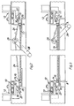
- Fig. 2
- einen Querschnitt durch die höhenverstellbare Scheibe mit Rahmen und mit Anpressorganen im nicht-dichtenden Zustand.
- Fig. 3
- einen Querschnitt durch die höhenverstellbare Scheibe mit Rahmen und mit Anpressorganen im abgedichteten Zustand, nach der Linie III-III in Fig. 5.
- Fig. 4
- einen Querschnitt durch die Abdichtorgane und mit Federmitteln zum Abheben der Scheibe in eine nicht-dichtende Lage
- Fig. 5
- eine schematische Darstellung der Anpressorgane zum dichtenden Anpressen der Scheibe an den stationären Rahmen
- Fig. 6
- einen Querschnitt durch eine Ausführungsvariante der Dichtorgane.
- Das Warmluft-Cheminée 1 gemäss Figur 1 enthält Seitenwände 2, die von einem äusseren Stahlmantel umgeben sind. Die Brennkammer 3 ist auf drei Seiten geschlossen und frontseitig offen.
Diese frontseitige Brennkammer-Oeffnung lässt sich durch eine höhenverstellbare Scheibe 17 überdecken. Die Scheibe 17 ist mit einem Scheibenrahmen 4 versehen, der in einem stationären Rahmen 12 geführt ist. Mit der Scheibe 17 wirkt ein in der Zeichnung nicht näher dargestelltes Gegengewicht zusammen, sodass die Scheibe 17 samt ihrem Rahmen 4 mit geringem Kraftaufwand angehoben oder abgesenkt werden kann. - Im Unterteil 11 befindet sich seitlich eine Anschlussöffnung 5 für die Zufuhr von zu erwärmender Frischluft. Auf der Oberseite sind zwei Warmluft-Austrittöffnungen 6 sowie eine Kaminöffnung 7 für den Abzug der Abgase vorgesehen. Für eine zeitlich und mengenmässige geregelte Zufuhr von Verbrennungsluft zur Brennkammer 3 sind frontseitig unterhalb des Brennraumbodens 13 schlitzartige Verbrennungsluft-Oeffnungen 8 vorhanden, welche durch Rohrleitungen oder Kanäle seitlich unter Umgehung der frontseitigen Oeffnung in das Innere der Brennkammer 3 einmünden. Mit diesen Verbrennungsluft-Oeffnungen 8 wirkt eine Drosseleinrichtung zusammen. Diese enthält beispielsweise einen linear beweglichen Schieber 21 mit Drosselöffnungen 23. Diese Drosseleinrichtung kann entweder manuell oder motorisch verstellt werden. Bei geschlossener Scheibe 17 ist dies die einzige Verbrennungsluft-Zufuhr zur Brennkammer 3. Die Drosseleinrichtung lässt sich zeitlich so steuern und regeln, dass die Verbrennungsluft-Zufuhr dem fortschreitenden Verbrennungsvorgang angepasst wird.
- Die Scheibe 17 besteht vorzugsweise aus feuerfestem Glas und ist durchsichtig, sodass sie Einblick in den Verbrennungsraum erlaubt. Die Scheibe 17 ist entlang des Randes mit einer Wärmeisolationsschicht versehen. Der Scheibenrahmen 4 hat vorzugsweise im Querschnitt eine U-Form, wobei die offene Seite gegen den Innenraum der Brennkammer 3 gerichtet ist. In den Scheibenrahmen 4 ist eine aus feuerfestem Material bestehende Dichtleiste 16 eingesetzt.
- Die Scheibe 17 kann ausseredem durch Scharniere um eine Vertikalachse relativ zum Scheibenrahmen 4 schwenkbar ausgebildet werden, um die Reinigung zu erleichtern.
- Damit der Scheibenrahmen 4 gegenüber dem stationären Rahmen 12 dicht abgeschlossen werden kann und damit eine Zufuhr von unerwünschter Fremdluft zur Brennkammer 3 vermieden wird, sind Anpressorgane vorhanden, mit denen die Scheibe 17 bzw. der Scheibenrahmen 4 dicht gegen den stationären Rahmen 12 andrückbar ist, wie dies aus den Figuren 2-4 hervorgeht.
- Der höhenverstellbare Scheibenrahmen 4 gleitet in zwei vertikale Kugelschienen 10 die je seitlich des Scheibenrahmens 4 angeordnet sind. Der stationäre Rahmen 12 enthält vier in einem Rechteck oder Quadrat angeordnete Schenkel 14, die sich rechtwinklig zur Scheibenfläche erstrecken und die zum Zusammenwirken mit der den Scheibenrahmen 4 umgebenden Dichtleiste 16 bestimmt sind. Die Dichtleiste 16 könnte auch als Metallfeder ausgebildet sein, welche durch das Anliegen an der Stirnseite der Schenkel 14 einen dichten Abschluss ergibt.
- In Fig. 2 ist der Scheibenrahmen im entspannten - also nichtdichtenden - Zustand dargestellt, wobei sich zwischen der Dichtleiste 16 und der Stirnfläche der Schenkel 14 je ein Zwischenraum 25 befindet. Um den Scheibenrahmen 4 gegen den Schenkel 14 anzudrücken und dadurch eine Abdichtung zu bewirken, sind Anpressorgane vorhanden, die nachfolgend näher beschrieben werden. Beidseits des Scheibenrahmens 4 ist je eine vertikale Stange 18 vorhanden, die je um eine vertikale Achse in mindestens einem Lagerkörper 44 schwenkbar gelagert ist. Jede dieser beiden Stangen 18 enthält an ihrem oberen Ende erste Anpressorgane in Form je einer radial abstehenden Nase 20 sowie am untern Ende eine radial abragende Lasche 22. In die beiden Laschen 22 greift je eine Zugstange 24 ein, die je gelenkig mit einem gemeinsamen Drehorgan in Form eines im stationären Rahmen gelagerten Drehtellers 26 verbunden sind. Der Drehteller 26 ist kraftschlüssig an einem Handhebel 28 befestigt mit dem eine Schwenkbewegung ausgeführt werden kann. Wenn dieser Schwenkhebel 28 von der in Fig. 2 ausgehenden Lage nach rechts in die in Fig. 3 dargestellte Lage verschwenkt wird, bewirkt dies eine gegenläufige Schwenkbewegung der beiden Stangen 18 und mit diesen der Nasen 20. Diese Nasen 20 drücken sodann je gegen zweite Anpressorgane in Form von Anschlägen 30 des Scheibenrahmens 4, wodurch dieser quer zu seiner Breitseite in Richtung der Pfeile A bewegt wird. Dadurch wird die Dichtleiste 16 gegen das stirnseitige Ende des Schenkels 14 angedrückt, sodas eine Abdichtung erfolgt. In dieser Dichtungslage der Scheibe 4 kann Verbrennungsluft einzig über die drosselbaren Oeffnungen 8 in das Innere der Brennkammer 3 gelangen.
- Aus Fig. 4 ist ersichtlich, dass der Scheibenrahmen 4 mittels Druckfedern 32 in die entspannte Lage gedrückt wird, wenn die Nasen 20 von den Anschlägen 30 abgehoben sind. Es sind mehrere voneinander distanzierte Druckfedern 32 vorhanden, welche je einen Bolzen 34 umgeben. Das Gewindeende dieser Bolzen 34 wird in eine mit Gewindebohrungen versehene Leiste oder eine Mutter 19 des Scheibenrahmens 4 eingeschraubt. Das andere mit einem Kopf 35 versehene Bolzenende ist in einer Buchse 36 axial verschiebbar gehalten. Wenn der Scheibenrahmen 4 gegen die Schenkel 14 angedrückt wird, bewegt sich der Bolzen 34 in den Hohlraum 37 oberhalb des Bolzenkopfes 35 hinein, wobei die Druckfedern 32 zusammengedrückt werden. In der nicht-dichtenden Lage lässt sich die Scheibe samt ihrem Rahmen 4 vertikal leichtgängig bewegen.
- In Fig. 5 ist eine Ausführungsvariante dargestellt, bei welcher anstelle des Handhebels 28 ein motorischer Antrieb für die Anpressorgane vorhanden ist. Ein Elektromotor 40 ist über eine Antriebsstange 42 mit dem Drehteller 26 verbunden. Der übrige Aufbau entspricht demjenigen gemäss den Figuren 2 und 3. Mit dem höhenverstellbaren Scheibenrahmen 4 wirkt eine Steuereinrichtung in der Weise zusammen, dass sich der Scheibenrahmen 4 nur in seiner geschlossenen Lage anpressen oder entspannen lässt. Zu diesem Zwecke ist eine Betätigungsstange 46 vorhanden, deren oberes Ende mit dem Scheibenrahmen 4 zum Zusammenwirken bestimmt ist und die durch eine Feder 48 belastet ist. Das untere Ende wirkt mit einem elektrischen Schalter 50 zusammen, der seinerseits bewirkt, dass der Motor nur dann Strom erhält, wenn sich der Scheibenrahmen 4 in seiner untersten, also geschlossenen Lage befindet. Dadurch wird verhindert, dass die Scheibe 4 in Zwischenstellungen blockiert werden kann.
- Fig. 6 zeigt eine Ausführungsvariante der Dichtungsorgane. An Stelle der aus feuerfestem Material bestehenden Dichtleiste 16 ist hier eine aus flexiblem Metall bestehende Blattfeder 16' vorhanden, die in den Rahmen 4 hineinragt und durch eine Zwischenlage 39 an der Scheibe 17 befestigt ist. Beim Andrücken der Scheibe 17 gegen den stationären Rahmen liegt der Schenkel 14 gegen die nachgiebige Blattfeder 16' an und bewirkt dadurch eine Abdichtung.
Claims (4)
- Warmluft-Cheminée mit einer Brennkammer (3) die von Seitenwänden (2) umgeben ist, die Brennkammer (3) über eine frontale Oeffnung zugänglich ist, die durch eine höhenverstellbare, in einem stationären Rahmen (12) geführte Scheibe (17) überdeckbar ist, dass - unter Umgehung der durch die Scheibe (17) überdeckbare Brennkammer-Oeffnung - mindestens ein Zufuhrkanal für die der Brennkammer (3) zuzuführende Verbrennungsluft vorhanden ist, die Scheibe (17) quer zu ihrer Breitseite abgestützt ist, Anpressorgane (20,30) vorhanden sind, mit denen die Scheibe (17) in ihrer Schliesslage gegen den stationären Rahmen (12) dicht anpressbar ist, dadurch gekennzeichnet, dass erste Anpressorgane (20) vorhanden sind, die von je einer im randnahen Bereich der Scheibe (17) angeordneten, verdrehbaren, vertikalen Stange (18) radial abragen und die mit zweiten Anpressorganen (30) im seitlichen Bereich des Scheibenrahmens (4) zusammenwirken, die untern Stangenenden je über Verbindungsorgane (24) mit einem gemeinsamen, in einem ortsfesten Teil gelagerten Drehorgan (26) gelenkig verbunden sind und quer zur Breitseite der Scheibe (17) wirksame Federn (32) zum Abheben der Scheibe (17) vom stationären Rahmen (12) im entspannten Zustand vorhanden sind.
- Warmluft-Cheminée nach Anspruch 1, dadurch gekennzeichnt, dass mit dem Drehorgan (26) ein schwenkbarer Handhebel (28) verbunden ist.
- Warmluft-Cheminée nach Anspruch 1, dadurch gekennzeichnet, dass mit dem Drehorgan (26) ein elektrischer Antriebsmotor (40) verbunden ist und ein dem Antriebsmotor (40) zugeordneter elektrischer Schalter (50) vorhanden ist, welcher ein Inbetriebsetzen des Antriebsmotores (40) nur in der geschlossenen Scheibenlage gestattet.
- Warmluft-Cheminée nach einem der Ansprüche 1-3, dadurch gekennzeichnet, dass zur Abdichtung eine metallische Blattfeder (16') vorhanden ist, die über eine Zwischenlage (39) mit der Scheibe (17) verbunden ist und zur Abdichtung gegen einen vorstehenden Schenkel (14) des stationären Rahmens anliegt.
Applications Claiming Priority (2)
| Application Number | Priority Date | Filing Date | Title |
|---|---|---|---|
| CH698/92 | 1992-03-05 | ||
| CH69892 | 1992-03-05 |
Publications (2)
| Publication Number | Publication Date |
|---|---|
| EP0559618A1 EP0559618A1 (de) | 1993-09-08 |
| EP0559618B1 true EP0559618B1 (de) | 1995-10-25 |
Family
ID=4193081
Family Applications (1)
| Application Number | Title | Priority Date | Filing Date |
|---|---|---|---|
| EP93810139A Expired - Lifetime EP0559618B1 (de) | 1992-03-05 | 1993-02-26 | Warmluft-Cheminée |
Country Status (3)
| Country | Link |
|---|---|
| EP (1) | EP0559618B1 (de) |
| AT (1) | ATE129556T1 (de) |
| DE (1) | DE59300802D1 (de) |
Families Citing this family (4)
| Publication number | Priority date | Publication date | Assignee | Title |
|---|---|---|---|---|
| BE1013297A3 (fr) * | 2000-02-23 | 2001-11-06 | Concept Et Forme Sprl | Foyer multifonctionnel. |
| DE102004021712A1 (de) * | 2004-04-30 | 2005-11-24 | Cera-Design By Britta Von Tasch Gmbh | Ofen oder Kamin und Verfahren zum Verschließen eines Feuerstellenhauptzugangs |
| DE102008025155A1 (de) * | 2008-05-26 | 2009-12-03 | Stachel Ag | Kamineinsatzheizkollektor |
| DE102008025156A1 (de) * | 2008-05-26 | 2009-12-03 | Stachel Ag | Glaskeramikscheibenheizung |
Citations (1)
| Publication number | Priority date | Publication date | Assignee | Title |
|---|---|---|---|---|
| GB2206962A (en) * | 1987-03-13 | 1989-01-18 | Vermont Castings | Fireplace doors |
Family Cites Families (3)
| Publication number | Priority date | Publication date | Assignee | Title |
|---|---|---|---|---|
| GB2209662B (en) * | 1987-09-11 | 1990-12-12 | Scot Young Serv Syst Ltd | Sweep mop pad holder |
| CH675467A5 (en) * | 1987-12-14 | 1990-09-28 | Rueegg Chemineebau Ag | Fireplace heater with incorporated casing - which has closable aperture and air duct for combustion chamber supply |
| FR2654496B1 (fr) * | 1989-11-13 | 1992-02-28 | Belot Andre | Dispositif d'obturation de l'ouverture de chargement de foyer d'une cheminee a foyer ferme et une cheminee avec systeme de commande du volet de reglage du tirage equipee d'un tel dispositif. |
-
1993
- 1993-02-26 AT AT93810139T patent/ATE129556T1/de not_active IP Right Cessation
- 1993-02-26 DE DE59300802T patent/DE59300802D1/de not_active Expired - Fee Related
- 1993-02-26 EP EP93810139A patent/EP0559618B1/de not_active Expired - Lifetime
Patent Citations (1)
| Publication number | Priority date | Publication date | Assignee | Title |
|---|---|---|---|---|
| GB2206962A (en) * | 1987-03-13 | 1989-01-18 | Vermont Castings | Fireplace doors |
Also Published As
| Publication number | Publication date |
|---|---|
| EP0559618A1 (de) | 1993-09-08 |
| ATE129556T1 (de) | 1995-11-15 |
| DE59300802D1 (de) | 1995-11-30 |
Similar Documents
| Publication | Publication Date | Title |
|---|---|---|
| DE2545514C3 (de) | Gleitschiebervorrichtung für mit Bodenauslaßöffnungen versehene Gießgefäße | |
| EP2354698A2 (de) | Lüftungsgitter zum Einbau in eine Aussenwand | |
| EP0559618B1 (de) | Warmluft-Cheminée | |
| EP0819488B1 (de) | Schiebeverschluss für einen Metallschmelze enthaltenden Behälter | |
| DE4003779A1 (de) | Ofen, insbesondere kaminofen, mit einem sekundaerluftkanal | |
| DE4441784C2 (de) | Sicherheitswerkbank | |
| EP0496043B1 (de) | Mit festen Brennstoffen betriebener Heizofen | |
| DE1974061U (de) | Turanordnung fuer waermebehandlungsoefen. | |
| DE2602811C3 (de) | Raumheizgerät | |
| DE2924118C2 (de) | Schieberverschluß für eine Gießpfanne | |
| DE60104032T2 (de) | Feuerstelle für mehrere Funktionen | |
| EP0085369B1 (de) | Verfahren zur Kokstrockenkühlung und geeigneter Kühlschacht | |
| DE570280C (de) | Bedienungsbank fuer OEfen | |
| DE2532097A1 (de) | Ofenkammerverschluss fuer einen koksofen | |
| EP1015820B1 (de) | Feuerraumverschliessvorrichtung | |
| DE3041029A1 (de) | Bodenverschluss fuer einen schmelzofen, insbesondere einen lichtbogenschmelzofen | |
| DE3108483A1 (de) | Fuellochverschlusseinrichtung fuer horizontale verkokungsoefen | |
| AT396719B (de) | Vorrichtung zur regelung der verbrennungsluftzufuhr bei einem ofen | |
| DE69209731T2 (de) | Güterwagen mit verschiebbarer Abdeckung | |
| DE69602346T2 (de) | Gasofen zum Durchlauferhitzen von Metallbarren | |
| CH675467A5 (en) | Fireplace heater with incorporated casing - which has closable aperture and air duct for combustion chamber supply | |
| EP0559619B1 (de) | Cheminée mit Primär- und Sekundärluft | |
| DE1433858A1 (de) | Schachtofenhaube,insbesondere fuer Schachtoefen zum Brennen von Zement,Dolomit,Magnesit u.dgl. | |
| DE914456C (de) | Hochdruckabsperrschieber | |
| WO2013189583A1 (de) | Hydraulische presse |
Legal Events
| Date | Code | Title | Description |
|---|---|---|---|
| PUAI | Public reference made under article 153(3) epc to a published international application that has entered the european phase |
Free format text: ORIGINAL CODE: 0009012 |
|
| AK | Designated contracting states |
Kind code of ref document: A1 Designated state(s): AT BE CH DE DK ES FR GB IT LI LU NL PT SE |
|
| 17P | Request for examination filed |
Effective date: 19931007 |
|
| 17Q | First examination report despatched |
Effective date: 19940620 |
|
| GRAA | (expected) grant |
Free format text: ORIGINAL CODE: 0009210 |
|
| AK | Designated contracting states |
Kind code of ref document: B1 Designated state(s): AT BE CH DE DK ES FR GB IT LI LU NL PT SE |
|
| PG25 | Lapsed in a contracting state [announced via postgrant information from national office to epo] |
Ref country code: GB Effective date: 19951025 Ref country code: ES Free format text: THE PATENT HAS BEEN ANNULLED BY A DECISION OF A NATIONAL AUTHORITY Effective date: 19951025 Ref country code: DK Effective date: 19951025 |
|
| REF | Corresponds to: |
Ref document number: 129556 Country of ref document: AT Date of ref document: 19951115 Kind code of ref document: T |
|
| REF | Corresponds to: |
Ref document number: 59300802 Country of ref document: DE Date of ref document: 19951130 |
|
| REG | Reference to a national code |
Ref country code: CH Ref legal event code: NV Representative=s name: PATENTANWALTSBUREAU BOSSHARD UND LUCHS |
|
| ITF | It: translation for a ep patent filed | ||
| PG25 | Lapsed in a contracting state [announced via postgrant information from national office to epo] |
Ref country code: SE Effective date: 19960125 Ref country code: PT Effective date: 19960125 |
|
| PG25 | Lapsed in a contracting state [announced via postgrant information from national office to epo] |
Ref country code: LU Free format text: LAPSE BECAUSE OF NON-PAYMENT OF DUE FEES Effective date: 19960229 |
|
| ET | Fr: translation filed | ||
| GBV | Gb: ep patent (uk) treated as always having been void in accordance with gb section 77(7)/1977 [no translation filed] |
Effective date: 19951025 |
|
| PLBE | No opposition filed within time limit |
Free format text: ORIGINAL CODE: 0009261 |
|
| STAA | Information on the status of an ep patent application or granted ep patent |
Free format text: STATUS: NO OPPOSITION FILED WITHIN TIME LIMIT |
|
| 26N | No opposition filed | ||
| PGFP | Annual fee paid to national office [announced via postgrant information from national office to epo] |
Ref country code: NL Payment date: 20020214 Year of fee payment: 10 Ref country code: AT Payment date: 20020214 Year of fee payment: 10 |
|
| PGFP | Annual fee paid to national office [announced via postgrant information from national office to epo] |
Ref country code: FR Payment date: 20020221 Year of fee payment: 10 Ref country code: BE Payment date: 20020221 Year of fee payment: 10 |
|
| PGFP | Annual fee paid to national office [announced via postgrant information from national office to epo] |
Ref country code: CH Payment date: 20020226 Year of fee payment: 10 |
|
| PGFP | Annual fee paid to national office [announced via postgrant information from national office to epo] |
Ref country code: DE Payment date: 20020227 Year of fee payment: 10 |
|
| PG25 | Lapsed in a contracting state [announced via postgrant information from national office to epo] |
Ref country code: AT Free format text: LAPSE BECAUSE OF NON-PAYMENT OF DUE FEES Effective date: 20030226 |
|
| PG25 | Lapsed in a contracting state [announced via postgrant information from national office to epo] |
Ref country code: LI Free format text: LAPSE BECAUSE OF NON-PAYMENT OF DUE FEES Effective date: 20030228 Ref country code: CH Free format text: LAPSE BECAUSE OF NON-PAYMENT OF DUE FEES Effective date: 20030228 Ref country code: BE Free format text: LAPSE BECAUSE OF NON-PAYMENT OF DUE FEES Effective date: 20030228 |
|
| PG25 | Lapsed in a contracting state [announced via postgrant information from national office to epo] |
Ref country code: NL Free format text: LAPSE BECAUSE OF NON-PAYMENT OF DUE FEES Effective date: 20030901 |
|
| PG25 | Lapsed in a contracting state [announced via postgrant information from national office to epo] |
Ref country code: DE Free format text: LAPSE BECAUSE OF NON-PAYMENT OF DUE FEES Effective date: 20030902 |
|
| REG | Reference to a national code |
Ref country code: CH Ref legal event code: PL |
|
| PG25 | Lapsed in a contracting state [announced via postgrant information from national office to epo] |
Ref country code: FR Free format text: LAPSE BECAUSE OF NON-PAYMENT OF DUE FEES Effective date: 20031031 |
|
| NLV4 | Nl: lapsed or anulled due to non-payment of the annual fee |
Effective date: 20030901 |
|
| REG | Reference to a national code |
Ref country code: FR Ref legal event code: ST |
|
| PG25 | Lapsed in a contracting state [announced via postgrant information from national office to epo] |
Ref country code: IT Free format text: LAPSE BECAUSE OF NON-PAYMENT OF DUE FEES;WARNING: LAPSES OF ITALIAN PATENTS WITH EFFECTIVE DATE BEFORE 2007 MAY HAVE OCCURRED AT ANY TIME BEFORE 2007. THE CORRECT EFFECTIVE DATE MAY BE DIFFERENT FROM THE ONE RECORDED. Effective date: 20050226 |