EP0559618B1 - Cheminée à chauffage d'air - Google Patents
Cheminée à chauffage d'air Download PDFInfo
- Publication number
- EP0559618B1 EP0559618B1 EP93810139A EP93810139A EP0559618B1 EP 0559618 B1 EP0559618 B1 EP 0559618B1 EP 93810139 A EP93810139 A EP 93810139A EP 93810139 A EP93810139 A EP 93810139A EP 0559618 B1 EP0559618 B1 EP 0559618B1
- Authority
- EP
- European Patent Office
- Prior art keywords
- panel
- combustion chamber
- air
- provision
- combustion
- Prior art date
- Legal status (The legal status is an assumption and is not a legal conclusion. Google has not performed a legal analysis and makes no representation as to the accuracy of the status listed.)
- Expired - Lifetime
Links
- 238000002485 combustion reaction Methods 0.000 claims abstract description 44
- 238000007789 sealing Methods 0.000 claims description 19
- 230000035515 penetration Effects 0.000 abstract 1
- 239000000126 substance Substances 0.000 abstract 1
- 239000002912 waste gas Substances 0.000 abstract 1
- 230000006835 compression Effects 0.000 description 3
- 238000007906 compression Methods 0.000 description 3
- 239000003344 environmental pollutant Substances 0.000 description 2
- 239000000446 fuel Substances 0.000 description 2
- 239000002184 metal Substances 0.000 description 2
- 239000011819 refractory material Substances 0.000 description 2
- 230000001105 regulatory effect Effects 0.000 description 2
- 229910000831 Steel Inorganic materials 0.000 description 1
- 238000004140 cleaning Methods 0.000 description 1
- 238000006073 displacement reaction Methods 0.000 description 1
- 230000000694 effects Effects 0.000 description 1
- 238000000605 extraction Methods 0.000 description 1
- 239000007789 gas Substances 0.000 description 1
- 239000011521 glass Substances 0.000 description 1
- 238000009413 insulation Methods 0.000 description 1
- 231100000719 pollutant Toxicity 0.000 description 1
- 239000010959 steel Substances 0.000 description 1
Images


Classifications
-
- F—MECHANICAL ENGINEERING; LIGHTING; HEATING; WEAPONS; BLASTING
- F24—HEATING; RANGES; VENTILATING
- F24B—DOMESTIC STOVES OR RANGES FOR SOLID FUELS; IMPLEMENTS FOR USE IN CONNECTION WITH STOVES OR RANGES
- F24B1/00—Stoves or ranges
- F24B1/18—Stoves with open fires, e.g. fireplaces
- F24B1/191—Component parts; Accessories
- F24B1/192—Doors; Screens; Fuel guards
Definitions
- the invention relates to a hot-air fireplace with a combustion chamber which is surrounded by side walls, the combustion chamber is accessible via a front opening, which can be covered by a height-adjustable pane guided in a stationary frame, that - bypassing the one that can be covered by the pane Combustion chamber opening - there is at least one supply channel for the combustion air to be supplied to the combustion chamber, the disc is movably supported transversely to its broad side and pressure elements are available with which the disc can be pressed tightly against the stationary frame in its closed position.
- the combustion air is supplied through a combustion chamber opening on the front, which can be closed more or less as required by a height-adjustable, usually transparent disc. It shows, however, that the combustion air in the combustion chamber should be regulated and metered for low-pollutant combustion with high efficiency. On the one hand, this requires a closed disc and a combustion air supply, bypassing the usual front opening of the combustion chamber. Even when the disc is closed, however, it cannot be avoided that foreign air that interferes with the front enters the combustion chamber.
- a fireplace with a front height-adjustable pane is known, means being available to press the pane tightly against a stationary frame.
- the air required for the combustion process is fed to the combustion chamber separately.
- a heat exchanger is available for the heat release into the surrounding space, whereby an outer and an inner shell are present.
- For pressing the window onto the stationary frame in the lower end position there are cranked guide rails on both sides as roller guides for the window frame. This configuration requires a relatively large amount of constructive means.
- the fireproof seal rubs against the stationary frame during the seal movement, which can wear or damage it.
- CH-A-675 467 shows a fireplace in which the fire opening can be sealed off by means of a vertically sliding window.
- the air required to maintain the combustion process is fed to the fireplace in a separate duct. Sealing takes place without movement of the window transversely to its broad side by sloping ramp plates against which the seal comes to rest in the closed position.
- the object of the invention is to improve a warm air fireplace of the type mentioned at the outset in such a way that the height-adjustable disc can be sealed relative to the combustion chamber with comparatively simple means and a smooth height displacement of the disc is possible without friction of the seal on stationary parts .
- first pressing members are present, which radially project from a rotatable, vertical rod arranged in the area near the edge of the disc and which cooperate with second pressing elements in the lateral region of the disc frame, the lower rod ends of which are each connected in an articulated manner via connecting elements to a common rotating element mounted in a fixed part and effective springs are provided transversely to the broad side of the pane for lifting the pane from the stationary frame in the relaxed state.
- the hot-air fireplace 1 contains side walls 2 which are surrounded by an outer steel jacket.
- the combustion chamber 3 is closed on three sides and open on the front.
- This front-side combustion chamber opening can be covered by a height-adjustable disk 17.
- the disc 17 is provided with a disc frame 4 which is guided in a stationary frame 12.
- a counterweight not shown in the drawing, interacts with the disk 17, so that the disk 17 together with its frame 4 can be raised or lowered with little effort.
- connection opening 5 On the side for the supply of fresh air to be heated.
- two hot air outlet openings 6 and a chimney opening 7 are provided for the extraction of the exhaust gases.
- slot-like combustion air openings 8 on the front below the combustion chamber floor 13, which open laterally into the interior of the combustion chamber 3 through pipelines or channels, bypassing the front opening.
- a throttle device interacts with these combustion air openings 8. This contains, for example, a linearly movable slide 21 with throttle openings 23. This throttle device can be adjusted either manually or by motor. When the disc 17 is closed, this is the only combustion air supply to the combustion chamber 3.
- the throttle device can be controlled and regulated in time so that the combustion air supply is adapted to the ongoing combustion process.
- the pane 17 is preferably made of fireproof glass and is transparent so that it allows an insight into the combustion chamber.
- the disc 17 is provided with a heat insulation layer along the edge.
- the pane frame 4 preferably has a U-shape in cross section, the open side being directed towards the interior of the combustion chamber 3.
- a sealing strip 16 made of refractory material is inserted into the pane frame 4.
- the pane 17 can also be designed to be pivotable about a vertical axis relative to the pane frame 4 in order to facilitate cleaning.
- pane frame 4 can be sealed against the stationary frame 12 and thus a supply of unwanted external air to the combustion chamber 3 is avoided, pressure elements are available with which the pane 17 or the pane frame 4 can be pressed tightly against the stationary frame 12, such as this is evident from Figures 2-4.
- the height-adjustable pane frame 4 slides into two vertical ball rails 10, which are each arranged to the side of the pane frame 4.
- the stationary frame 12 contains four legs 14 arranged in a rectangle or square, which extend at right angles to the pane surface and which are intended to interact with the sealing strip 16 surrounding the pane frame 4.
- the sealing strip 16 could also be designed as a metal spring, which results in a tight seal due to the abutment on the end face of the legs 14.
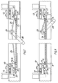
- the window frame is shown in the relaxed - ie non-sealing - state, with an intermediate space 25 between the sealing strip 16 and the end face of the legs 14.
- pressure elements are provided, which are described in more detail below.
- Each of these two rods 18 contains at their upper end first pressing members in the form of a radially projecting nose 20 and at the lower end a radially protruding tab 22.
- a pull rod 24 engages in each of the two tabs 22, each of which is articulated with a common rotating member Form of a stored in the stationary frame
- Turntables 26 are connected.
- the turntable 26 is non-positively attached to a hand lever 28 with which a pivoting movement can be carried out. If this pivot lever 28 is pivoted from the position in FIG. 2 to the right into the position shown in FIG. 3, this causes a counter-pivoting movement of the two rods 18 and with these of the lugs 20.
- These lugs 20 then each press against second pressing members in the form of stops 30 of the window frame 4, whereby this is moved transversely to its broad side in the direction of arrows A.
- Characterized the sealing strip 16 is pressed against the front end of the leg 14, so that a seal is made. In this sealing position of the disc 4, combustion air can only get into the interior of the combustion chamber 3 via the throttle openings 8.
- the window frame 4 is pressed into the relaxed position by means of compression springs 32 when the lugs 20 are lifted off the stops 30.
- compression springs 32 There are a plurality of spaced apart compression springs 32 which each surround a bolt 34.
- the threaded end of these bolts 34 is screwed into a bar provided with threaded holes or a nut 19 of the window frame 4.
- the other bolt end provided with a head 35 is held axially displaceably in a bush 36.
- FIG. 5 shows an embodiment variant in which a motor drive for the pressing members is provided instead of the hand lever 28.
- An electric motor 40 is connected to the turntable 26 via a drive rod 42.
- the remaining structure corresponds to that according to FIGS. 2 and 3.
- a control device interacts with the height-adjustable pane frame 4 in such a way that the pane frame 4 can only be pressed or relaxed in its closed position.
- actuating rod 46 the upper end of which is intended to cooperate with the window frame 4 and which is loaded by a spring 48.
- the lower end cooperates with an electrical switch 50, which in turn causes the motor to receive power only when the window frame 4 is in its lowermost, that is to say closed, position. This prevents the disk 4 from being blocked in intermediate positions.
- FIG. 6 shows an embodiment variant of the sealing members.
- a leaf spring 16 'made of flexible metal is present, which protrudes into the frame 4 and is fastened to the pane 17 by an intermediate layer 39.
- the leg 14 bears against the resilient leaf spring 16 'and thereby causes a seal.
Landscapes
- Engineering & Computer Science (AREA)
- Chemical & Material Sciences (AREA)
- Combustion & Propulsion (AREA)
- Mechanical Engineering (AREA)
- General Engineering & Computer Science (AREA)
- Power-Operated Mechanisms For Wings (AREA)
- Wick-Type Burners And Burners With Porous Materials (AREA)
- Blow-Moulding Or Thermoforming Of Plastics Or The Like (AREA)
- Holding Or Fastening Of Disk On Rotational Shaft (AREA)
- Macromolecular Compounds Obtained By Forming Nitrogen-Containing Linkages In General (AREA)
Claims (4)
- Cheminée à air chaud comprenant une chambre de combustion (3) qui est entourée par des parois latérales (2) et est accessible par une ouverture frontale susceptible d'être recouverte par une vitre (17) mobile en hauteur, guidée dans un cadre stationnaire (12), au moins un canal d'amenée pour l'air de combustion à amener dans la chambre de combustion (3) étant prévu de manière à contourner l'ouverture de la chambre de combustion, susceptible d'être recouverte par la vitre (17), la vitre (17) étant soutenue transversalement à son côté large, et des organes de serrage (20,30) étant prévus, par lesquels la vitre (17), dans sa position de fermeture, petit être serrée de façon étanche contre le cadre stationnaire (12), caractérisé par le fait qu'elle comprend des premiers organes de serrage (20) qui font saillie radialement sur deux tiges verticales (17) rotatives, disposées chacune dans la zone proche d'un bord de la vitre (17) et coopérant avec des deuxièmes organes de serrage (30) dans la zone latérale du cadre de vitre (4), les extrémités inférieures des tiges étant reliées de façon articulée, respectivement par des organes de liaison (24), à un organe de rotation (26) commun, monté dans une partie stationnaire, et des ressorts (32) agissant transversalement au côté large de la vitre (17). étant prévus pour décoller la vitre (17) du cadre stationnaire (12) à l'état détendu.
- Cheminée fermé suivant la revendication 1, caractérisé par le fait qu'une poignée (28) pivotante est reliée à l'organe de rotation (26).
- Cheminée fermé suivant la revendication 1, caractérisé par le fait qu'un moteur d'entraînement électrique (40) est relié à l'organe de rotation (26) et qu'un interrupteur électrique (50) est associé au moteur d'entraînement (40) pour permettre la mise en marche du moteur d'entraînement (40) uniquement lorsque la vitre se trouve en position de fermeture.
- Cheminée fermé suivant l'une des revendications 1 à 3, caractérisé par le fait qu'en vue de l'étanchéité, il est prévu une lame de ressort métallique (16') qui est reliée par une couche intermédiaire (39) à la vitre (17) et est appliquée, en vue de l'étanchéité, contre une branche saillante (14) du cadre stationnaire.
Applications Claiming Priority (2)
| Application Number | Priority Date | Filing Date | Title |
|---|---|---|---|
| CH698/92 | 1992-03-05 | ||
| CH69892 | 1992-03-05 |
Publications (2)
| Publication Number | Publication Date |
|---|---|
| EP0559618A1 EP0559618A1 (fr) | 1993-09-08 |
| EP0559618B1 true EP0559618B1 (fr) | 1995-10-25 |
Family
ID=4193081
Family Applications (1)
| Application Number | Title | Priority Date | Filing Date |
|---|---|---|---|
| EP93810139A Expired - Lifetime EP0559618B1 (fr) | 1992-03-05 | 1993-02-26 | Cheminée à chauffage d'air |
Country Status (3)
| Country | Link |
|---|---|
| EP (1) | EP0559618B1 (fr) |
| AT (1) | ATE129556T1 (fr) |
| DE (1) | DE59300802D1 (fr) |
Families Citing this family (4)
| Publication number | Priority date | Publication date | Assignee | Title |
|---|---|---|---|---|
| BE1013297A3 (fr) * | 2000-02-23 | 2001-11-06 | Concept Et Forme Sprl | Foyer multifonctionnel. |
| DE102004021712A1 (de) * | 2004-04-30 | 2005-11-24 | Cera-Design By Britta Von Tasch Gmbh | Ofen oder Kamin und Verfahren zum Verschließen eines Feuerstellenhauptzugangs |
| DE102008025155A1 (de) * | 2008-05-26 | 2009-12-03 | Stachel Ag | Kamineinsatzheizkollektor |
| DE102008025156A1 (de) * | 2008-05-26 | 2009-12-03 | Stachel Ag | Glaskeramikscheibenheizung |
Citations (1)
| Publication number | Priority date | Publication date | Assignee | Title |
|---|---|---|---|---|
| GB2206962A (en) * | 1987-03-13 | 1989-01-18 | Vermont Castings | Fireplace doors |
Family Cites Families (3)
| Publication number | Priority date | Publication date | Assignee | Title |
|---|---|---|---|---|
| GB2209662B (en) * | 1987-09-11 | 1990-12-12 | Scot Young Serv Syst Ltd | Sweep mop pad holder |
| CH675467A5 (en) * | 1987-12-14 | 1990-09-28 | Rueegg Chemineebau Ag | Fireplace heater with incorporated casing - which has closable aperture and air duct for combustion chamber supply |
| FR2654496B1 (fr) * | 1989-11-13 | 1992-02-28 | Belot Andre | Dispositif d'obturation de l'ouverture de chargement de foyer d'une cheminee a foyer ferme et une cheminee avec systeme de commande du volet de reglage du tirage equipee d'un tel dispositif. |
-
1993
- 1993-02-26 AT AT93810139T patent/ATE129556T1/de not_active IP Right Cessation
- 1993-02-26 DE DE59300802T patent/DE59300802D1/de not_active Expired - Fee Related
- 1993-02-26 EP EP93810139A patent/EP0559618B1/fr not_active Expired - Lifetime
Patent Citations (1)
| Publication number | Priority date | Publication date | Assignee | Title |
|---|---|---|---|---|
| GB2206962A (en) * | 1987-03-13 | 1989-01-18 | Vermont Castings | Fireplace doors |
Also Published As
| Publication number | Publication date |
|---|---|
| EP0559618A1 (fr) | 1993-09-08 |
| ATE129556T1 (de) | 1995-11-15 |
| DE59300802D1 (de) | 1995-11-30 |
Similar Documents
| Publication | Publication Date | Title |
|---|---|---|
| DE2545514C3 (de) | Gleitschiebervorrichtung für mit Bodenauslaßöffnungen versehene Gießgefäße | |
| EP2354698A2 (fr) | Grille d'aération pour intégration murale extérieure | |
| EP0559618B1 (fr) | Cheminée à chauffage d'air | |
| EP0819488B1 (fr) | Fermeture à tiroir pour un récipient contenant un bain métallique en fusion | |
| DE4003779A1 (de) | Ofen, insbesondere kaminofen, mit einem sekundaerluftkanal | |
| DE4441784C2 (de) | Sicherheitswerkbank | |
| EP0496043B1 (fr) | Pôele de chauffage pour combustibles solides | |
| DE1974061U (de) | Turanordnung fuer waermebehandlungsoefen. | |
| DE2602811C3 (de) | Raumheizgerät | |
| DE2924118C2 (de) | Schieberverschluß für eine Gießpfanne | |
| DE60104032T2 (de) | Feuerstelle für mehrere Funktionen | |
| EP0085369B1 (fr) | Procédé pour le refroidissement à sec de coke et chambre de refroidissement | |
| DE570280C (de) | Bedienungsbank fuer OEfen | |
| DE2532097A1 (de) | Ofenkammerverschluss fuer einen koksofen | |
| EP1015820B1 (fr) | Dispositif de fermeture de foyer | |
| DE3041029A1 (de) | Bodenverschluss fuer einen schmelzofen, insbesondere einen lichtbogenschmelzofen | |
| DE3108483A1 (de) | Fuellochverschlusseinrichtung fuer horizontale verkokungsoefen | |
| AT396719B (de) | Vorrichtung zur regelung der verbrennungsluftzufuhr bei einem ofen | |
| DE69209731T2 (de) | Güterwagen mit verschiebbarer Abdeckung | |
| DE69602346T2 (de) | Gasofen zum Durchlauferhitzen von Metallbarren | |
| CH675467A5 (en) | Fireplace heater with incorporated casing - which has closable aperture and air duct for combustion chamber supply | |
| EP0559619B1 (fr) | Cheminée à air primaire et secondaire | |
| DE1433858A1 (de) | Schachtofenhaube,insbesondere fuer Schachtoefen zum Brennen von Zement,Dolomit,Magnesit u.dgl. | |
| DE914456C (de) | Hochdruckabsperrschieber | |
| WO2013189583A1 (fr) | Presse hydraulique |
Legal Events
| Date | Code | Title | Description |
|---|---|---|---|
| PUAI | Public reference made under article 153(3) epc to a published international application that has entered the european phase |
Free format text: ORIGINAL CODE: 0009012 |
|
| AK | Designated contracting states |
Kind code of ref document: A1 Designated state(s): AT BE CH DE DK ES FR GB IT LI LU NL PT SE |
|
| 17P | Request for examination filed |
Effective date: 19931007 |
|
| 17Q | First examination report despatched |
Effective date: 19940620 |
|
| GRAA | (expected) grant |
Free format text: ORIGINAL CODE: 0009210 |
|
| AK | Designated contracting states |
Kind code of ref document: B1 Designated state(s): AT BE CH DE DK ES FR GB IT LI LU NL PT SE |
|
| PG25 | Lapsed in a contracting state [announced via postgrant information from national office to epo] |
Ref country code: GB Effective date: 19951025 Ref country code: ES Free format text: THE PATENT HAS BEEN ANNULLED BY A DECISION OF A NATIONAL AUTHORITY Effective date: 19951025 Ref country code: DK Effective date: 19951025 |
|
| REF | Corresponds to: |
Ref document number: 129556 Country of ref document: AT Date of ref document: 19951115 Kind code of ref document: T |
|
| REF | Corresponds to: |
Ref document number: 59300802 Country of ref document: DE Date of ref document: 19951130 |
|
| REG | Reference to a national code |
Ref country code: CH Ref legal event code: NV Representative=s name: PATENTANWALTSBUREAU BOSSHARD UND LUCHS |
|
| ITF | It: translation for a ep patent filed | ||
| PG25 | Lapsed in a contracting state [announced via postgrant information from national office to epo] |
Ref country code: SE Effective date: 19960125 Ref country code: PT Effective date: 19960125 |
|
| PG25 | Lapsed in a contracting state [announced via postgrant information from national office to epo] |
Ref country code: LU Free format text: LAPSE BECAUSE OF NON-PAYMENT OF DUE FEES Effective date: 19960229 |
|
| ET | Fr: translation filed | ||
| GBV | Gb: ep patent (uk) treated as always having been void in accordance with gb section 77(7)/1977 [no translation filed] |
Effective date: 19951025 |
|
| PLBE | No opposition filed within time limit |
Free format text: ORIGINAL CODE: 0009261 |
|
| STAA | Information on the status of an ep patent application or granted ep patent |
Free format text: STATUS: NO OPPOSITION FILED WITHIN TIME LIMIT |
|
| 26N | No opposition filed | ||
| PGFP | Annual fee paid to national office [announced via postgrant information from national office to epo] |
Ref country code: NL Payment date: 20020214 Year of fee payment: 10 Ref country code: AT Payment date: 20020214 Year of fee payment: 10 |
|
| PGFP | Annual fee paid to national office [announced via postgrant information from national office to epo] |
Ref country code: FR Payment date: 20020221 Year of fee payment: 10 Ref country code: BE Payment date: 20020221 Year of fee payment: 10 |
|
| PGFP | Annual fee paid to national office [announced via postgrant information from national office to epo] |
Ref country code: CH Payment date: 20020226 Year of fee payment: 10 |
|
| PGFP | Annual fee paid to national office [announced via postgrant information from national office to epo] |
Ref country code: DE Payment date: 20020227 Year of fee payment: 10 |
|
| PG25 | Lapsed in a contracting state [announced via postgrant information from national office to epo] |
Ref country code: AT Free format text: LAPSE BECAUSE OF NON-PAYMENT OF DUE FEES Effective date: 20030226 |
|
| PG25 | Lapsed in a contracting state [announced via postgrant information from national office to epo] |
Ref country code: LI Free format text: LAPSE BECAUSE OF NON-PAYMENT OF DUE FEES Effective date: 20030228 Ref country code: CH Free format text: LAPSE BECAUSE OF NON-PAYMENT OF DUE FEES Effective date: 20030228 Ref country code: BE Free format text: LAPSE BECAUSE OF NON-PAYMENT OF DUE FEES Effective date: 20030228 |
|
| PG25 | Lapsed in a contracting state [announced via postgrant information from national office to epo] |
Ref country code: NL Free format text: LAPSE BECAUSE OF NON-PAYMENT OF DUE FEES Effective date: 20030901 |
|
| PG25 | Lapsed in a contracting state [announced via postgrant information from national office to epo] |
Ref country code: DE Free format text: LAPSE BECAUSE OF NON-PAYMENT OF DUE FEES Effective date: 20030902 |
|
| REG | Reference to a national code |
Ref country code: CH Ref legal event code: PL |
|
| PG25 | Lapsed in a contracting state [announced via postgrant information from national office to epo] |
Ref country code: FR Free format text: LAPSE BECAUSE OF NON-PAYMENT OF DUE FEES Effective date: 20031031 |
|
| NLV4 | Nl: lapsed or anulled due to non-payment of the annual fee |
Effective date: 20030901 |
|
| REG | Reference to a national code |
Ref country code: FR Ref legal event code: ST |
|
| PG25 | Lapsed in a contracting state [announced via postgrant information from national office to epo] |
Ref country code: IT Free format text: LAPSE BECAUSE OF NON-PAYMENT OF DUE FEES;WARNING: LAPSES OF ITALIAN PATENTS WITH EFFECTIVE DATE BEFORE 2007 MAY HAVE OCCURRED AT ANY TIME BEFORE 2007. THE CORRECT EFFECTIVE DATE MAY BE DIFFERENT FROM THE ONE RECORDED. Effective date: 20050226 |