EP0559618A1 - Cheminée à chauffage d'air - Google Patents
Cheminée à chauffage d'air Download PDFInfo
- Publication number
- EP0559618A1 EP0559618A1 EP93810139A EP93810139A EP0559618A1 EP 0559618 A1 EP0559618 A1 EP 0559618A1 EP 93810139 A EP93810139 A EP 93810139A EP 93810139 A EP93810139 A EP 93810139A EP 0559618 A1 EP0559618 A1 EP 0559618A1
- Authority
- EP
- European Patent Office
- Prior art keywords
- combustion chamber
- disc
- pane
- frame
- air
- Prior art date
- Legal status (The legal status is an assumption and is not a legal conclusion. Google has not performed a legal analysis and makes no representation as to the accuracy of the status listed.)
- Granted
Links
- 238000002485 combustion reaction Methods 0.000 claims abstract description 44
- 238000007789 sealing Methods 0.000 claims description 18
- 230000006835 compression Effects 0.000 claims description 4
- 238000007906 compression Methods 0.000 claims description 4
- 239000011819 refractory material Substances 0.000 claims description 3
- 230000035515 penetration Effects 0.000 abstract 1
- 239000000126 substance Substances 0.000 abstract 1
- 239000002912 waste gas Substances 0.000 abstract 1
- 239000003344 environmental pollutant Substances 0.000 description 2
- 239000000446 fuel Substances 0.000 description 2
- 239000007789 gas Substances 0.000 description 2
- 239000002184 metal Substances 0.000 description 2
- 230000001105 regulatory effect Effects 0.000 description 2
- 229910000831 Steel Inorganic materials 0.000 description 1
- 238000004140 cleaning Methods 0.000 description 1
- 230000000694 effects Effects 0.000 description 1
- 238000000605 extraction Methods 0.000 description 1
- 239000011521 glass Substances 0.000 description 1
- 238000009413 insulation Methods 0.000 description 1
- 231100000719 pollutant Toxicity 0.000 description 1
- 239000010959 steel Substances 0.000 description 1
Images


Classifications
-
- F—MECHANICAL ENGINEERING; LIGHTING; HEATING; WEAPONS; BLASTING
- F24—HEATING; RANGES; VENTILATING
- F24B—DOMESTIC STOVES OR RANGES FOR SOLID FUELS; IMPLEMENTS FOR USE IN CONNECTION WITH STOVES OR RANGES
- F24B1/00—Stoves or ranges
- F24B1/18—Stoves with open fires, e.g. fireplaces
- F24B1/191—Component parts; Accessories
- F24B1/192—Doors; Screens; Fuel guards
Definitions
- the invention relates to a warm air fireplace with a combustion chamber which is surrounded by side walls, the combustion chamber is accessible via a front opening, which can be covered by a height-adjustable disc guided in a stationary frame.
- the combustion air is supplied through a combustion chamber opening on the front, which can be closed more or less as required by a height-adjustable, usually transparent disc.
- a combustion chamber opening on the front which can be closed more or less as required by a height-adjustable, usually transparent disc.
- the combustion air should be regulated and metered for low-pollutant combustion with high efficiency.
- With the disc closed this requires an adjustable combustion air supply, bypassing the usual front opening of the combustion chamber. Even when the disc is closed, it cannot be avoided that foreign air from the front can enter the combustion chamber.
- the object is to be achieved, in a warm air fireplace of the type mentioned, to seal the height-adjustable disc in an airtight manner relative to the combustion chamber, in order to avoid an undesired supply of external air to the combustion zone and, on the other hand, to enable the disc to be easily moved in height if necessary.
- This object is achieved in that - bypassing the combustion chamber opening which can be covered by the disc - there is at least one supply channel for the combustion air to be supplied to the combustion chamber, the disc is movably supported transversely to its broad side, and there are pressing elements with which the disc in its closed position can be pressed tightly against the stationary frame and spring means are available for lifting the pane from the stationary frame in the relaxed state.
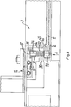
- the hot-air fireplace 1 contains side walls 2 which are surrounded by an outer steel jacket.
- the combustion chamber 2 is closed on three sides and open on the front.
- This front-side combustion chamber opening can be covered by a height-adjustable disk 17.
- the disc 17 is provided with a disc frame 4 which is guided in a stationary frame 9.
- a counterweight not shown in the drawing, interacts with the disk 17, so that the disk 17 together with its frame 4 can be raised or lowered with little effort.
- connection opening 5 On the side for the supply of fresh air to be heated.
- two hot air outlet openings 6 and a chimney opening 7 are provided for the extraction of the exhaust gases.
- slot-like combustion air openings 8 at the front below the combustion chamber floor 13, which open laterally into the interior of the combustion chamber 3 through pipelines or channels, bypassing the front opening.
- a throttle device interacts with these combustion air openings 8. This contains, for example, a linearly movable slide 21 with throttle openings 23. This throttle device can either be adjusted manually by a hand lever 28 or by a motor. When the disk 17 is closed, this is the only combustion air supply to the combustion chamber 3.
- the throttle device can be controlled and regulated in time so that the combustion air supply is adapted to the ongoing combustion process.
- the pane 17 is preferably made of fireproof glass and is transparent, so that it allows an insight into the combustion chamber.
- the disk 17 is provided with a heat insulation layer along the edge.
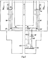
- the pane frame 4 preferably has a U-shape in cross section, the open side being directed towards the interior of the combustion chamber 3.
- a sealing strip 16 made of refractory material is inserted into the pane frame 4.
- the pane 15 can also be designed to be pivotable relative to the pane frame 4 by means of hinges in order to facilitate cleaning.
- the height-adjustable pane frame 4 slides into two vertical ball rails 10, which are each arranged to the side of the pane frame 4.
- the stationary frame 12 contains four legs 14 arranged in a rectangle or square, which extend at right angles to the pane surface and which are intended to interact with the sealing strip 16 surrounding the pane frame 4.
- the sealing strip 16 could also be designed as a metal spring, which results in a tight seal due to the abutment on the end face of the legs 14.
- Fig. 2 the window frame is shown in the relaxed - ie non-sealing - state, with an intermediate space 25 between the sealing strip 16 and the end face of the legs 14.
- pressure elements are present, which are described in more detail below.
- Each of these two rods 18 contains at its upper end a radially protruding shoulder in the form of a nose 20 and at the lower end a radially projecting tab 22.
- a pull rod 24 engages in each of the two tabs 22, each of which is articulated with a common rotating member one stored in the stationary frame
- Turntables 26 are connected.
- the turntable 26 is non-positively attached to a hand lever 28 with which a pivoting movement can be carried out. If this pivot lever 28 is pivoted from the position in FIG. 2 to the right into the position shown in FIG. 3, this causes the two rods 18 and with them the lugs 20 to rotate in opposite directions.
- These lugs 20 then each press against a stop 30 of the window frame 4, whereby this is moved transversely to its broad side in the direction of arrows A.
- Characterized the sealing strip 16 is pressed against the front end of the leg 14, so that a seal is made. In this sealing position of the disc 4, combustion air can only get into the interior of the combustion chamber 3 via the throttle openings 8.
- the window frame 4 is pressed into the relaxed position by means of compression springs 32 when the lugs 20 are lifted off the stop 30.
- compression springs 32 There are a plurality of spaced apart compression springs 32 which each surround a bolt 34.
- the threaded end of these bolts 34 is screwed into a bar provided with threaded holes or a nut 19 of the disk frame 4.
- the other bolt end provided with a head 35 is held axially displaceably in a bush 36.
- FIG. 5 shows an embodiment variant in which a motor drive for the pressing members is present instead of the hand lever 28.
- An electric motor 40 is connected to the turntable 26 via a drive rod 42.
- the remaining structure corresponds to that according to FIGS. 2 and 3.
- a control device interacts with the height-adjustable pane frame 4 in such a way that the pane frame 4 can only be pressed or relaxed in its closed position.
- there is an actuating rod 46 the upper end of which is intended to cooperate with the window frame 4 and which is loaded by a spring 48.
- the lower end interacts with an electrical switch 50, which in turn causes the motor to receive power only when the window frame 4 is in its lowest, ie closed, position. This prevents the disk 4 from being blocked in intermediate positions.
- Fig. 6 shows a variant of the sealing members.
- a leaf spring 16 'made of flexible metal is present, which protrudes into the frame 14 and is fastened to the disk 17 by an intermediate layer 39.
- the leg 14 bears against the resilient leaf spring 16 'and thereby causes a seal.
Landscapes
- Engineering & Computer Science (AREA)
- Chemical & Material Sciences (AREA)
- Combustion & Propulsion (AREA)
- Mechanical Engineering (AREA)
- General Engineering & Computer Science (AREA)
- Power-Operated Mechanisms For Wings (AREA)
- Wick-Type Burners And Burners With Porous Materials (AREA)
- Blow-Moulding Or Thermoforming Of Plastics Or The Like (AREA)
- Holding Or Fastening Of Disk On Rotational Shaft (AREA)
- Macromolecular Compounds Obtained By Forming Nitrogen-Containing Linkages In General (AREA)
Applications Claiming Priority (2)
| Application Number | Priority Date | Filing Date | Title |
|---|---|---|---|
| CH698/92 | 1992-03-05 | ||
| CH69892 | 1992-03-05 |
Publications (2)
| Publication Number | Publication Date |
|---|---|
| EP0559618A1 true EP0559618A1 (fr) | 1993-09-08 |
| EP0559618B1 EP0559618B1 (fr) | 1995-10-25 |
Family
ID=4193081
Family Applications (1)
| Application Number | Title | Priority Date | Filing Date |
|---|---|---|---|
| EP93810139A Expired - Lifetime EP0559618B1 (fr) | 1992-03-05 | 1993-02-26 | Cheminée à chauffage d'air |
Country Status (3)
| Country | Link |
|---|---|
| EP (1) | EP0559618B1 (fr) |
| AT (1) | ATE129556T1 (fr) |
| DE (1) | DE59300802D1 (fr) |
Cited By (4)
| Publication number | Priority date | Publication date | Assignee | Title |
|---|---|---|---|---|
| EP1130323A1 (fr) * | 2000-02-23 | 2001-09-05 | Concept et Forme Sprl | Foyer multifunctionnel |
| EP1591726A2 (fr) * | 2004-04-30 | 2005-11-02 | Cera-Design, by Britta v. Tasch GmbH | Poêle ou cheminée et méthode de fermeture de l'entrée principale de foyer |
| DE102008025155A1 (de) * | 2008-05-26 | 2009-12-03 | Stachel Ag | Kamineinsatzheizkollektor |
| DE102008025156A1 (de) * | 2008-05-26 | 2009-12-03 | Stachel Ag | Glaskeramikscheibenheizung |
Citations (3)
| Publication number | Priority date | Publication date | Assignee | Title |
|---|---|---|---|---|
| GB2209662A (en) * | 1987-09-11 | 1989-05-24 | Scot Young Serv Syst Ltd | Sweep mop pad holder |
| CH675467A5 (en) * | 1987-12-14 | 1990-09-28 | Rueegg Chemineebau Ag | Fireplace heater with incorporated casing - which has closable aperture and air duct for combustion chamber supply |
| FR2654496A1 (fr) * | 1989-11-13 | 1991-05-17 | Belot Andre | Dispositif d'obturation de l'ouverture de chargement de foyer d'une cheminee a foyer ferme et une cheminee avec systeme de commande du volet de reglage du tirage equipee d'un tel dispositif. |
Family Cites Families (1)
| Publication number | Priority date | Publication date | Assignee | Title |
|---|---|---|---|---|
| GB2206962A (en) * | 1987-03-13 | 1989-01-18 | Vermont Castings | Fireplace doors |
-
1993
- 1993-02-26 EP EP93810139A patent/EP0559618B1/fr not_active Expired - Lifetime
- 1993-02-26 AT AT93810139T patent/ATE129556T1/de not_active IP Right Cessation
- 1993-02-26 DE DE59300802T patent/DE59300802D1/de not_active Expired - Fee Related
Patent Citations (3)
| Publication number | Priority date | Publication date | Assignee | Title |
|---|---|---|---|---|
| GB2209662A (en) * | 1987-09-11 | 1989-05-24 | Scot Young Serv Syst Ltd | Sweep mop pad holder |
| CH675467A5 (en) * | 1987-12-14 | 1990-09-28 | Rueegg Chemineebau Ag | Fireplace heater with incorporated casing - which has closable aperture and air duct for combustion chamber supply |
| FR2654496A1 (fr) * | 1989-11-13 | 1991-05-17 | Belot Andre | Dispositif d'obturation de l'ouverture de chargement de foyer d'une cheminee a foyer ferme et une cheminee avec systeme de commande du volet de reglage du tirage equipee d'un tel dispositif. |
Cited By (7)
| Publication number | Priority date | Publication date | Assignee | Title |
|---|---|---|---|---|
| EP1130323A1 (fr) * | 2000-02-23 | 2001-09-05 | Concept et Forme Sprl | Foyer multifunctionnel |
| EP1445541A2 (fr) * | 2000-02-23 | 2004-08-11 | Concept et Forme Sprl | Foyer multifoncionnel |
| EP1445541A3 (fr) * | 2000-02-23 | 2006-05-17 | Concept et Forme Sprl | Foyer multifoncionnel |
| EP1591726A2 (fr) * | 2004-04-30 | 2005-11-02 | Cera-Design, by Britta v. Tasch GmbH | Poêle ou cheminée et méthode de fermeture de l'entrée principale de foyer |
| EP1591726A3 (fr) * | 2004-04-30 | 2008-05-07 | Cera-Design, by Britta v. Tasch GmbH | Poêle ou cheminée et méthode de fermeture de l'entrée principale de foyer |
| DE102008025155A1 (de) * | 2008-05-26 | 2009-12-03 | Stachel Ag | Kamineinsatzheizkollektor |
| DE102008025156A1 (de) * | 2008-05-26 | 2009-12-03 | Stachel Ag | Glaskeramikscheibenheizung |
Also Published As
| Publication number | Publication date |
|---|---|
| ATE129556T1 (de) | 1995-11-15 |
| EP0559618B1 (fr) | 1995-10-25 |
| DE59300802D1 (de) | 1995-11-30 |
Similar Documents
| Publication | Publication Date | Title |
|---|---|---|
| DE3148196C3 (de) | Anordnung zur Oberflächenbehandlung eines Gegenstandes mit Infrarotheizkörpern | |
| EP2354698A2 (fr) | Grille d'aération pour intégration murale extérieure | |
| EP0819488B1 (fr) | Fermeture à tiroir pour un récipient contenant un bain métallique en fusion | |
| EP0559618B1 (fr) | Cheminée à chauffage d'air | |
| EP0496043B1 (fr) | Pôele de chauffage pour combustibles solides | |
| DE4441784C2 (de) | Sicherheitswerkbank | |
| DE2602811C3 (de) | Raumheizgerät | |
| DE2804941A1 (de) | Schrumpfvorrichtung zum einschrumpfen von stueckguetern | |
| DE3108483C2 (de) | Füllochverschlußeinrichtung für horizontale Verkokungsöfen | |
| EP0085369B1 (fr) | Procédé pour le refroidissement à sec de coke et chambre de refroidissement | |
| DE3939170C2 (de) | Verschlußklappe für einen Schachtofen | |
| DE570280C (de) | Bedienungsbank fuer OEfen | |
| EP1719870A2 (fr) | Porte avec dispositif d'étanchéité | |
| DE102018127623A1 (de) | Gasdichte Absperrklappe | |
| EP1015820B1 (fr) | Dispositif de fermeture de foyer | |
| DE3304512C2 (fr) | ||
| DE69209731T2 (de) | Güterwagen mit verschiebbarer Abdeckung | |
| DE29514367U1 (de) | Hochschiebbarer Kamintürrahmen | |
| CH675467A5 (en) | Fireplace heater with incorporated casing - which has closable aperture and air duct for combustion chamber supply | |
| DE2913942A1 (de) | Absperrschieber | |
| AT11165U1 (de) | Vorrichtung für das automatisierbare zuführen von scheitholz und ähnlichen brennstoffen zu einem verbrennungsofen | |
| DE8220533U1 (de) | Schwenktor | |
| DE19548085B4 (de) | Lösbare Montierung eines Sturzbrenners auf einen Heizkessel | |
| DE719946C (de) | Beschickungsvorrichtung fuer Industrieoefen | |
| AT402557B (de) | Brennraumtür für eine heizeinrichtung |
Legal Events
| Date | Code | Title | Description |
|---|---|---|---|
| PUAI | Public reference made under article 153(3) epc to a published international application that has entered the european phase |
Free format text: ORIGINAL CODE: 0009012 |
|
| AK | Designated contracting states |
Kind code of ref document: A1 Designated state(s): AT BE CH DE DK ES FR GB IT LI LU NL PT SE |
|
| 17P | Request for examination filed |
Effective date: 19931007 |
|
| 17Q | First examination report despatched |
Effective date: 19940620 |
|
| GRAA | (expected) grant |
Free format text: ORIGINAL CODE: 0009210 |
|
| AK | Designated contracting states |
Kind code of ref document: B1 Designated state(s): AT BE CH DE DK ES FR GB IT LI LU NL PT SE |
|
| PG25 | Lapsed in a contracting state [announced via postgrant information from national office to epo] |
Ref country code: GB Effective date: 19951025 Ref country code: ES Free format text: THE PATENT HAS BEEN ANNULLED BY A DECISION OF A NATIONAL AUTHORITY Effective date: 19951025 Ref country code: DK Effective date: 19951025 |
|
| REF | Corresponds to: |
Ref document number: 129556 Country of ref document: AT Date of ref document: 19951115 Kind code of ref document: T |
|
| REF | Corresponds to: |
Ref document number: 59300802 Country of ref document: DE Date of ref document: 19951130 |
|
| REG | Reference to a national code |
Ref country code: CH Ref legal event code: NV Representative=s name: PATENTANWALTSBUREAU BOSSHARD UND LUCHS |
|
| ITF | It: translation for a ep patent filed | ||
| PG25 | Lapsed in a contracting state [announced via postgrant information from national office to epo] |
Ref country code: SE Effective date: 19960125 Ref country code: PT Effective date: 19960125 |
|
| PG25 | Lapsed in a contracting state [announced via postgrant information from national office to epo] |
Ref country code: LU Free format text: LAPSE BECAUSE OF NON-PAYMENT OF DUE FEES Effective date: 19960229 |
|
| ET | Fr: translation filed | ||
| GBV | Gb: ep patent (uk) treated as always having been void in accordance with gb section 77(7)/1977 [no translation filed] |
Effective date: 19951025 |
|
| PLBE | No opposition filed within time limit |
Free format text: ORIGINAL CODE: 0009261 |
|
| STAA | Information on the status of an ep patent application or granted ep patent |
Free format text: STATUS: NO OPPOSITION FILED WITHIN TIME LIMIT |
|
| 26N | No opposition filed | ||
| PGFP | Annual fee paid to national office [announced via postgrant information from national office to epo] |
Ref country code: NL Payment date: 20020214 Year of fee payment: 10 Ref country code: AT Payment date: 20020214 Year of fee payment: 10 |
|
| PGFP | Annual fee paid to national office [announced via postgrant information from national office to epo] |
Ref country code: FR Payment date: 20020221 Year of fee payment: 10 Ref country code: BE Payment date: 20020221 Year of fee payment: 10 |
|
| PGFP | Annual fee paid to national office [announced via postgrant information from national office to epo] |
Ref country code: CH Payment date: 20020226 Year of fee payment: 10 |
|
| PGFP | Annual fee paid to national office [announced via postgrant information from national office to epo] |
Ref country code: DE Payment date: 20020227 Year of fee payment: 10 |
|
| PG25 | Lapsed in a contracting state [announced via postgrant information from national office to epo] |
Ref country code: AT Free format text: LAPSE BECAUSE OF NON-PAYMENT OF DUE FEES Effective date: 20030226 |
|
| PG25 | Lapsed in a contracting state [announced via postgrant information from national office to epo] |
Ref country code: LI Free format text: LAPSE BECAUSE OF NON-PAYMENT OF DUE FEES Effective date: 20030228 Ref country code: CH Free format text: LAPSE BECAUSE OF NON-PAYMENT OF DUE FEES Effective date: 20030228 Ref country code: BE Free format text: LAPSE BECAUSE OF NON-PAYMENT OF DUE FEES Effective date: 20030228 |
|
| PG25 | Lapsed in a contracting state [announced via postgrant information from national office to epo] |
Ref country code: NL Free format text: LAPSE BECAUSE OF NON-PAYMENT OF DUE FEES Effective date: 20030901 |
|
| PG25 | Lapsed in a contracting state [announced via postgrant information from national office to epo] |
Ref country code: DE Free format text: LAPSE BECAUSE OF NON-PAYMENT OF DUE FEES Effective date: 20030902 |
|
| REG | Reference to a national code |
Ref country code: CH Ref legal event code: PL |
|
| PG25 | Lapsed in a contracting state [announced via postgrant information from national office to epo] |
Ref country code: FR Free format text: LAPSE BECAUSE OF NON-PAYMENT OF DUE FEES Effective date: 20031031 |
|
| NLV4 | Nl: lapsed or anulled due to non-payment of the annual fee |
Effective date: 20030901 |
|
| REG | Reference to a national code |
Ref country code: FR Ref legal event code: ST |
|
| PG25 | Lapsed in a contracting state [announced via postgrant information from national office to epo] |
Ref country code: IT Free format text: LAPSE BECAUSE OF NON-PAYMENT OF DUE FEES;WARNING: LAPSES OF ITALIAN PATENTS WITH EFFECTIVE DATE BEFORE 2007 MAY HAVE OCCURRED AT ANY TIME BEFORE 2007. THE CORRECT EFFECTIVE DATE MAY BE DIFFERENT FROM THE ONE RECORDED. Effective date: 20050226 |