EP0557919A1 - Dispositif pour mélanger et/ou malaxer des matériaux - Google Patents
Dispositif pour mélanger et/ou malaxer des matériaux Download PDFInfo
- Publication number
- EP0557919A1 EP0557919A1 EP93102734A EP93102734A EP0557919A1 EP 0557919 A1 EP0557919 A1 EP 0557919A1 EP 93102734 A EP93102734 A EP 93102734A EP 93102734 A EP93102734 A EP 93102734A EP 0557919 A1 EP0557919 A1 EP 0557919A1
- Authority
- EP
- European Patent Office
- Prior art keywords
- shaft
- wedge
- section
- cross
- wedges
- Prior art date
- Legal status (The legal status is an assumption and is not a legal conclusion. Google has not performed a legal analysis and makes no representation as to the accuracy of the status listed.)
- Granted
Links
Images


Classifications
-
- B—PERFORMING OPERATIONS; TRANSPORTING
- B01—PHYSICAL OR CHEMICAL PROCESSES OR APPARATUS IN GENERAL
- B01F—MIXING, e.g. DISSOLVING, EMULSIFYING OR DISPERSING
- B01F27/00—Mixers with rotary stirring devices in fixed receptacles; Kneaders
- B01F27/05—Stirrers
- B01F27/07—Stirrers characterised by their mounting on the shaft
- B01F27/071—Fixing of the stirrer to the shaft
-
- Y—GENERAL TAGGING OF NEW TECHNOLOGICAL DEVELOPMENTS; GENERAL TAGGING OF CROSS-SECTIONAL TECHNOLOGIES SPANNING OVER SEVERAL SECTIONS OF THE IPC; TECHNICAL SUBJECTS COVERED BY FORMER USPC CROSS-REFERENCE ART COLLECTIONS [XRACs] AND DIGESTS
- Y10—TECHNICAL SUBJECTS COVERED BY FORMER USPC
- Y10T—TECHNICAL SUBJECTS COVERED BY FORMER US CLASSIFICATION
- Y10T403/00—Joints and connections
- Y10T403/70—Interfitted members
- Y10T403/7018—Interfitted members including separably interposed key
-
- Y—GENERAL TAGGING OF NEW TECHNOLOGICAL DEVELOPMENTS; GENERAL TAGGING OF CROSS-SECTIONAL TECHNOLOGIES SPANNING OVER SEVERAL SECTIONS OF THE IPC; TECHNICAL SUBJECTS COVERED BY FORMER USPC CROSS-REFERENCE ART COLLECTIONS [XRACs] AND DIGESTS
- Y10—TECHNICAL SUBJECTS COVERED BY FORMER USPC
- Y10T—TECHNICAL SUBJECTS COVERED BY FORMER US CLASSIFICATION
- Y10T403/00—Joints and connections
- Y10T403/70—Interfitted members
- Y10T403/7047—Radially interposed shim or bushing
- Y10T403/7051—Wedging or camming
Definitions
- the invention relates to a device for mixing and / or kneading viscous, plastic, powdery or granular substances, consisting of a drivable worm shaft arranged in a tubular housing opening, which consists of a shaft transmitting the torque and a plurality arranged one behind the other and by means of at least one Wedge with a substantially rectangular cross-section rotatably connected to this screw elements as a partial load, in which the wedge is arranged partly in the shaft and partly in the screw elements such that the long sides of the wedge cross section parallel to the tangent to the shaft circumference and its short sides in the right Angles to the long sides are arranged.
- Such a device is known (DE - C - 813 154).
- the aim of kneading with this device is to transfer as much energy as possible from the driven shaft to the material to be processed in the device, which is converted into work in it.
- the wedge or wedges between the shaft and screw elements have the task of positioning the screw elements in the correct rotational position on the shaft and the torque during operation from the shaft via the screw elements in the material to be processed.
- a swelling torsional load of the shaft occurs in only one direction, which stresses it for fatigue strength.
- the maximum stress concentration that occurs in the keyway and whose maximum permissible value must not be exceeded is decisive for the load capacity of the shaft.
- the wedge or the wedges are arranged in such a way that their cross-section lies radially and symmetrically about half each in the shaft and in the screw elements. This results in a groove base that is not optimally designed against the notch effect and poor accessibility of the groove for testing and cleaning.
- the technical problem underlying the invention is therefore to improve the coupling between the shaft and screw elements and the performance of the shaft in such a way that the transmissible torque can be increased without increasing the dimensions.
- FIG. 1 illustrates the cross section of a worm shaft machine which consists of the shaft 1 and a plurality of worm elements 2 arranged one behind the other and offset in the circumferential direction, of which only one worm element is shown.
- the screw element 2 is positively coupled to the shaft by the wedges 3.
- a worm shaft formed in this way is rotatable in the circular inner bore of the housing 4 arranged.
- the worm shaft machine can also be designed so that it has several worm shafts, which requires a corresponding housing. If the worm shaft machine contains two worm shafts, the inner bore of the housing has the shape of a lying figure eight.
- the worm shafts can either be driven in opposite directions or in the same direction.
- arrow 5 shows the direction of rotation of the worm shaft. Operation in the opposite direction of rotation is not possible.
- each wedge has an approximately rectangular cross section (apart from the rounded corners), which has an outer long side 6, an inner long side 7 and two short sides 8 and 9.
- the wedge 3 is arranged in the shaft 1 and the screw element 2 such that its long side 6 is congruent with the tangent 10 to the shaft circumference.
- the long side 7 of the wedge cross section is parallel to the long side 6 and the short sides are perpendicular to the long sides.
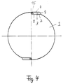
- the position of the wedges in the shaft and the screw element shown in FIG. 2 is the optimal embodiment.
- the short side 8 is completely immersed in the shaft 1 and the short side 9 is completely immersed in the screw element (not shown in FIG. 2). Therefore, the short sides 8 and 9 of the wedge are only subjected to pressure during operation.
- the optimal position of the wedges 3 shown in FIG. 2 can be deviated to a certain extent without a significant deterioration in the wedge stress. This could happen, for example, by a slight parallel displacement of the wedge 3 outwards and to the side.
- FIGS. 3a to 3d show different embodiments of an elastic wedge 3.
- longitudinal grooves 11 running parallel to the longitudinal edges have been introduced into the wedge, one of which is open on the top and one on the underside of the wedge is.
- oblique cuts 12 are present in the wedge.
- the cuts 13 run parallel to the longitudinal edges of the wedge or also at right angles thereto.
- the cuts 14 are only parallel to the longitudinal axes of the wedge, but have a different arrangement than in FIG. 3 c.
- wedges 3 show another embodiment of the wedges 3. These wedges are not made of feathers, but solid. They also have long pages 6 and 7 and short pages 8 and 9. However, the short side 8 is designed in the manner of a fillet and an elastic tube 15 is arranged between it and the opposite groove wall in the shaft.
Applications Claiming Priority (3)
| Application Number | Priority Date | Filing Date | Title |
|---|---|---|---|
| DE4206219A DE4206219A1 (de) | 1992-02-28 | 1992-02-28 | Vorrichtung zum mischen und/oder kneten von werkstoffen |
| DE4206219 | 1992-02-28 | ||
| US08/014,372 US5314245A (en) | 1992-02-28 | 1993-02-05 | Arrangement for mixing and kneading of materials with a screw shaft and at least one screw element connected with one another by wedges |
Publications (2)
| Publication Number | Publication Date |
|---|---|
| EP0557919A1 true EP0557919A1 (fr) | 1993-09-01 |
| EP0557919B1 EP0557919B1 (fr) | 1996-06-05 |
Family
ID=25912314
Family Applications (1)
| Application Number | Title | Priority Date | Filing Date |
|---|---|---|---|
| EP93102734A Expired - Lifetime EP0557919B1 (fr) | 1992-02-28 | 1993-02-22 | Dispositif pour mélanger et/ou malaxer des matériaux |
Country Status (5)
| Country | Link |
|---|---|
| US (1) | US5314245A (fr) |
| EP (1) | EP0557919B1 (fr) |
| JP (1) | JP3176747B2 (fr) |
| AT (1) | ATE138829T1 (fr) |
| DE (2) | DE4206219A1 (fr) |
Families Citing this family (6)
| Publication number | Priority date | Publication date | Assignee | Title |
|---|---|---|---|---|
| DE4421514C2 (de) * | 1994-06-20 | 1998-08-13 | Krupp Werner & Pfleiderer Gmbh | Schneckenmaschine mit aufsteckbaren Schneckensatzelementen |
| US7188992B2 (en) * | 2003-07-30 | 2007-03-13 | Americhem, Inc. | Kneading element and related articles |
| US7192178B2 (en) * | 2004-02-19 | 2007-03-20 | J. C. Steele & Sons, Inc. | Extrusion auger with removable auger segments and removal tool |
| FR2971190B1 (fr) * | 2011-02-09 | 2013-03-08 | Michelin Soc Tech | Vis destinee a l'extrusion ou au melangeage d'elastomeres ou de produits plastiques pour la fabrication de pneumatiques |
| US20160061249A1 (en) * | 2014-08-29 | 2016-03-03 | Douglas H. Powell | Adjustable shear key |
| DE102015005790A1 (de) * | 2015-05-10 | 2016-11-10 | Reifenhäuser GmbH & Co. KG Maschinenfabrik | Schnecke zum Einsatz in einem Extruder, Verfahren zum Umrüsten einer Schnecke und Extruder |
Citations (4)
| Publication number | Priority date | Publication date | Assignee | Title |
|---|---|---|---|---|
| DE813154C (de) * | 1949-09-29 | 1951-09-06 | Bayer Ag | Misch- und Knetvorrichtung |
| US3155056A (en) * | 1959-08-26 | 1964-11-03 | American Mach & Foundry | Plastic or dough mixing apparatus |
| EP0001970A1 (fr) * | 1977-11-12 | 1979-05-30 | Werner & Pfleiderer | Rotor de malaxage pour extrudeuses à vis |
| EP0422272A1 (fr) * | 1989-10-12 | 1991-04-17 | Josef A. Blach | Dispositif de malaxage et pétrissage |
Family Cites Families (24)
| Publication number | Priority date | Publication date | Assignee | Title |
|---|---|---|---|---|
| US118474A (en) * | 1871-08-29 | Improvement in shaft-couplings | ||
| US248400A (en) * | 1881-10-18 | Self-adjusting spline or key | ||
| US732738A (en) * | 1901-12-02 | 1903-07-07 | Charles Hammen | Keys and key-seats for shafting. |
| US1460222A (en) * | 1922-05-26 | 1923-06-26 | Int Harvester Co | Machine key |
| FR567959A (fr) * | 1922-09-08 | 1924-03-12 | Cie Forges Et Acieries Marine | Dispositif pour la fixation des volants sur leur arbre |
| DE423465C (de) * | 1923-04-11 | 1926-01-04 | Bbc Brown Boveri & Cie | Befestigung von Turbinenscheiben auf ihrer Welle durch federnde Ringe |
| FR761657A (fr) * | 1933-09-19 | 1934-03-24 | Protectoglass Ltd | Perfectionnements aux procédés de fabrication des verres de sécurité |
| US2681239A (en) * | 1950-08-16 | 1954-06-15 | James W Gillen | Pressure lock key |
| GB868469A (en) * | 1957-05-16 | 1961-05-17 | Huntley & Palmers Ltd | Improvements in continuously operable apparatus for kneading plastic masses |
| US2994548A (en) * | 1958-04-03 | 1961-08-01 | Donald H Mcgogy | Shaft keying device |
| FR1345563A (fr) * | 1961-12-14 | 1963-12-13 | Perfectionnement aux clavetages tangentiels | |
| DE1180718B (de) * | 1962-04-11 | 1964-11-05 | Bayer Ag | Knetvorrichtung mit zwei oder mehr Schnecken |
| FR1416667A (fr) * | 1963-11-15 | 1965-11-05 | Wmb Internat Ab | Procédé pour la fabrication de corps poreux en matière thermoplastique |
| NL131340C (fr) * | 1963-11-27 | 1900-01-01 | ||
| DE6604741U (de) * | 1966-02-11 | 1970-02-19 | Werner & Pfleiderer | Schneckenmaschine |
| US3421783A (en) * | 1967-08-30 | 1969-01-14 | Sakai Mfg Co Ltd | Shock-absorbing key for rotary body |
| GB1215057A (en) * | 1968-05-22 | 1970-12-09 | Laminated Plastic Products Ltd | Demountable agitator |
| DE2329514A1 (de) * | 1973-06-06 | 1975-01-02 | Mannesmann Meer Ag | Auf einem wellenzapfen drehfest aufgestecktes zahnrad grossen durchmessers |
| DE2617864A1 (de) * | 1976-04-23 | 1977-11-03 | Nosta Normteile Und Stahlkeile | Kraftuebertragungselement |
| SU724820A1 (ru) * | 1978-09-06 | 1980-03-30 | Orenbojm Boris D | Шпоночное соединение |
| US4358215A (en) * | 1980-10-20 | 1982-11-09 | Rivin Evgeny I | Key connection |
| DE3406665C2 (de) * | 1984-02-24 | 1986-10-23 | Fraunhofer-Gesellschaft zur Förderung der angewandten Forschung e.V., 8000 München | Schneckenextruder zur Verarbeitung von Explosivstoffen |
| US4875847A (en) * | 1984-04-23 | 1989-10-24 | Wenger Manufacturing, Inc. | Twin-screw extruder having respective conical nose screw sections |
| GB8804313D0 (en) * | 1988-02-24 | 1988-03-23 | Apv Plc | Improvements in/relating to mixers |
-
1992
- 1992-02-28 DE DE4206219A patent/DE4206219A1/de not_active Withdrawn
-
1993
- 1993-02-05 US US08/014,372 patent/US5314245A/en not_active Expired - Lifetime
- 1993-02-22 DE DE59302775T patent/DE59302775D1/de not_active Expired - Lifetime
- 1993-02-22 AT AT93102734T patent/ATE138829T1/de not_active IP Right Cessation
- 1993-02-22 EP EP93102734A patent/EP0557919B1/fr not_active Expired - Lifetime
- 1993-02-25 JP JP03645993A patent/JP3176747B2/ja not_active Expired - Fee Related
Patent Citations (4)
| Publication number | Priority date | Publication date | Assignee | Title |
|---|---|---|---|---|
| DE813154C (de) * | 1949-09-29 | 1951-09-06 | Bayer Ag | Misch- und Knetvorrichtung |
| US3155056A (en) * | 1959-08-26 | 1964-11-03 | American Mach & Foundry | Plastic or dough mixing apparatus |
| EP0001970A1 (fr) * | 1977-11-12 | 1979-05-30 | Werner & Pfleiderer | Rotor de malaxage pour extrudeuses à vis |
| EP0422272A1 (fr) * | 1989-10-12 | 1991-04-17 | Josef A. Blach | Dispositif de malaxage et pétrissage |
Also Published As
| Publication number | Publication date |
|---|---|
| EP0557919B1 (fr) | 1996-06-05 |
| JPH07251053A (ja) | 1995-10-03 |
| US5314245A (en) | 1994-05-24 |
| JP3176747B2 (ja) | 2001-06-18 |
| DE4206219A1 (de) | 1993-09-02 |
| ATE138829T1 (de) | 1996-06-15 |
| DE59302775D1 (de) | 1996-07-11 |
Similar Documents
| Publication | Publication Date | Title |
|---|---|---|
| EP0422272B1 (fr) | Dispositif de malaxage et pétrissage | |
| DE2360440C3 (de) | Spurkettengelenkglied | |
| DE3044415A1 (de) | Elastische kupplung zum uebertragen einer drehbewegung | |
| EP1147841A1 (fr) | Plaquette de coupe et outil pour fraiser | |
| DE3032537C2 (fr) | ||
| DE3417555C2 (fr) | ||
| EP0557919B1 (fr) | Dispositif pour mélanger et/ou malaxer des matériaux | |
| EP0318669B1 (fr) | Accouplement à rondelles élastiques | |
| DE2542321A1 (de) | Kopplungsanordnung fuer dynamoelektrische maschine | |
| DE2655728C2 (de) | Lösbare Naben-Wellenverbindung | |
| EP3234389B1 (fr) | Élément d'accouplement et dispositif d'accouplement pour la transmission axiale de couple et ensemble de lamelles pour de tels éléments d'accouplement | |
| EP0013274A1 (fr) | Organes de liaison mécaniques et outil de fixation approprié | |
| DE3828131C2 (fr) | ||
| DE19732663A1 (de) | Drehmomentübertragungsvorrichtung zur spielfreien Drehmomentübertragung zwischen einer Welle und einem dazu komplementären Körper | |
| EP0178537B1 (fr) | Méthode pour attacher des éléments d'entraînement aux essieux à l'aide de clavettes coupant ces essieux axialement et en particulier ces éléments | |
| CH672906A5 (fr) | ||
| DE2534135C3 (de) | Klauenkupplung mit elastischen Kissen | |
| DE3013957A1 (de) | Gesenk-auswechselvorrichtung | |
| DE2601388A1 (de) | Passbolzenanordnung | |
| EP0273172B1 (fr) | Rouleau convoyeur pour l'alimentation d'éléments en bois, en matériaux similaires ou en matière plastique | |
| WO2002066849A1 (fr) | Entraineur a bride | |
| DE2807120C2 (de) | Wälzfräser mit eingesetzten Schneiden | |
| DE2156030A1 (de) | Kettenradsatz | |
| DE3444141A1 (de) | Kompensator | |
| DE2932879A1 (de) | Konstruktion zur kraftschluessigen verbindung mechanischer bauteile, insbesondere zur ausbildung montierter naben |
Legal Events
| Date | Code | Title | Description |
|---|---|---|---|
| PUAI | Public reference made under article 153(3) epc to a published international application that has entered the european phase |
Free format text: ORIGINAL CODE: 0009012 |
|
| AK | Designated contracting states |
Kind code of ref document: A1 Designated state(s): AT BE CH DE ES FR GB IT LI NL |
|
| 17P | Request for examination filed |
Effective date: 19931221 |
|
| 17Q | First examination report despatched |
Effective date: 19941208 |
|
| GRAA | (expected) grant |
Free format text: ORIGINAL CODE: 0009210 |
|
| AK | Designated contracting states |
Kind code of ref document: B1 Designated state(s): AT BE CH DE ES FR GB IT LI NL |
|
| PG25 | Lapsed in a contracting state [announced via postgrant information from national office to epo] |
Ref country code: NL Free format text: LAPSE BECAUSE OF FAILURE TO SUBMIT A TRANSLATION OF THE DESCRIPTION OR TO PAY THE FEE WITHIN THE PRESCRIBED TIME-LIMIT Effective date: 19960605 Ref country code: ES Free format text: THE PATENT HAS BEEN ANNULLED BY A DECISION OF A NATIONAL AUTHORITY Effective date: 19960605 |
|
| REF | Corresponds to: |
Ref document number: 138829 Country of ref document: AT Date of ref document: 19960615 Kind code of ref document: T |
|
| REF | Corresponds to: |
Ref document number: 59302775 Country of ref document: DE Date of ref document: 19960711 |
|
| ET | Fr: translation filed | ||
| GBT | Gb: translation of ep patent filed (gb section 77(6)(a)/1977) |
Effective date: 19960626 |
|
| GRAH | Despatch of communication of intention to grant a patent |
Free format text: ORIGINAL CODE: EPIDOS IGRA |
|
| ITF | It: translation for a ep patent filed |
Owner name: STUDIO JAUMANN |
|
| NLV1 | Nl: lapsed or annulled due to failure to fulfill the requirements of art. 29p and 29m of the patents act | ||
| PG25 | Lapsed in a contracting state [announced via postgrant information from national office to epo] |
Ref country code: LI Effective date: 19970228 Ref country code: CH Effective date: 19970228 Ref country code: BE Effective date: 19970228 |
|
| PLBE | No opposition filed within time limit |
Free format text: ORIGINAL CODE: 0009261 |
|
| STAA | Information on the status of an ep patent application or granted ep patent |
Free format text: STATUS: NO OPPOSITION FILED WITHIN TIME LIMIT |
|
| 26N | No opposition filed | ||
| PGFP | Annual fee paid to national office [announced via postgrant information from national office to epo] |
Ref country code: AT Payment date: 19970801 Year of fee payment: 5 |
|
| REG | Reference to a national code |
Ref country code: CH Ref legal event code: PL |
|
| PGFP | Annual fee paid to national office [announced via postgrant information from national office to epo] |
Ref country code: GB Payment date: 19980212 Year of fee payment: 6 |
|
| PG25 | Lapsed in a contracting state [announced via postgrant information from national office to epo] |
Ref country code: AT Free format text: LAPSE BECAUSE OF NON-PAYMENT OF DUE FEES Effective date: 19980222 |
|
| PG25 | Lapsed in a contracting state [announced via postgrant information from national office to epo] |
Ref country code: GB Free format text: LAPSE BECAUSE OF NON-PAYMENT OF DUE FEES Effective date: 19990222 |
|
| PGFP | Annual fee paid to national office [announced via postgrant information from national office to epo] |
Ref country code: FR Payment date: 19990226 Year of fee payment: 7 |
|
| GBPC | Gb: european patent ceased through non-payment of renewal fee |
Effective date: 19990222 |
|
| PG25 | Lapsed in a contracting state [announced via postgrant information from national office to epo] |
Ref country code: FR Free format text: LAPSE BECAUSE OF NON-PAYMENT OF DUE FEES Effective date: 20001031 |
|
| REG | Reference to a national code |
Ref country code: FR Ref legal event code: ST |
|
| PG25 | Lapsed in a contracting state [announced via postgrant information from national office to epo] |
Ref country code: IT Free format text: LAPSE BECAUSE OF NON-PAYMENT OF DUE FEES;WARNING: LAPSES OF ITALIAN PATENTS WITH EFFECTIVE DATE BEFORE 2007 MAY HAVE OCCURRED AT ANY TIME BEFORE 2007. THE CORRECT EFFECTIVE DATE MAY BE DIFFERENT FROM THE ONE RECORDED. Effective date: 20050222 |
|
| PGFP | Annual fee paid to national office [announced via postgrant information from national office to epo] |
Ref country code: DE Payment date: 20120222 Year of fee payment: 20 |
|
| REG | Reference to a national code |
Ref country code: DE Ref legal event code: R071 Ref document number: 59302775 Country of ref document: DE |
|
| PG25 | Lapsed in a contracting state [announced via postgrant information from national office to epo] |
Ref country code: DE Free format text: LAPSE BECAUSE OF EXPIRATION OF PROTECTION Effective date: 20130223 |