EP0557919A1 - Device for mixing and/or kneading materials - Google Patents
Device for mixing and/or kneading materials Download PDFInfo
- Publication number
- EP0557919A1 EP0557919A1 EP93102734A EP93102734A EP0557919A1 EP 0557919 A1 EP0557919 A1 EP 0557919A1 EP 93102734 A EP93102734 A EP 93102734A EP 93102734 A EP93102734 A EP 93102734A EP 0557919 A1 EP0557919 A1 EP 0557919A1
- Authority
- EP
- European Patent Office
- Prior art keywords
- shaft
- wedge
- section
- cross
- wedges
- Prior art date
- Legal status (The legal status is an assumption and is not a legal conclusion. Google has not performed a legal analysis and makes no representation as to the accuracy of the status listed.)
- Granted
Links
Images


Classifications
-
- B—PERFORMING OPERATIONS; TRANSPORTING
- B01—PHYSICAL OR CHEMICAL PROCESSES OR APPARATUS IN GENERAL
- B01F—MIXING, e.g. DISSOLVING, EMULSIFYING OR DISPERSING
- B01F27/00—Mixers with rotary stirring devices in fixed receptacles; Kneaders
- B01F27/05—Stirrers
- B01F27/07—Stirrers characterised by their mounting on the shaft
- B01F27/071—Fixing of the stirrer to the shaft
-
- Y—GENERAL TAGGING OF NEW TECHNOLOGICAL DEVELOPMENTS; GENERAL TAGGING OF CROSS-SECTIONAL TECHNOLOGIES SPANNING OVER SEVERAL SECTIONS OF THE IPC; TECHNICAL SUBJECTS COVERED BY FORMER USPC CROSS-REFERENCE ART COLLECTIONS [XRACs] AND DIGESTS
- Y10—TECHNICAL SUBJECTS COVERED BY FORMER USPC
- Y10T—TECHNICAL SUBJECTS COVERED BY FORMER US CLASSIFICATION
- Y10T403/00—Joints and connections
- Y10T403/70—Interfitted members
- Y10T403/7018—Interfitted members including separably interposed key
-
- Y—GENERAL TAGGING OF NEW TECHNOLOGICAL DEVELOPMENTS; GENERAL TAGGING OF CROSS-SECTIONAL TECHNOLOGIES SPANNING OVER SEVERAL SECTIONS OF THE IPC; TECHNICAL SUBJECTS COVERED BY FORMER USPC CROSS-REFERENCE ART COLLECTIONS [XRACs] AND DIGESTS
- Y10—TECHNICAL SUBJECTS COVERED BY FORMER USPC
- Y10T—TECHNICAL SUBJECTS COVERED BY FORMER US CLASSIFICATION
- Y10T403/00—Joints and connections
- Y10T403/70—Interfitted members
- Y10T403/7047—Radially interposed shim or bushing
- Y10T403/7051—Wedging or camming
Definitions
- the invention relates to a device for mixing and / or kneading viscous, plastic, powdery or granular substances, consisting of a drivable worm shaft arranged in a tubular housing opening, which consists of a shaft transmitting the torque and a plurality arranged one behind the other and by means of at least one Wedge with a substantially rectangular cross-section rotatably connected to this screw elements as a partial load, in which the wedge is arranged partly in the shaft and partly in the screw elements such that the long sides of the wedge cross section parallel to the tangent to the shaft circumference and its short sides in the right Angles to the long sides are arranged.
- Such a device is known (DE - C - 813 154).
- the aim of kneading with this device is to transfer as much energy as possible from the driven shaft to the material to be processed in the device, which is converted into work in it.
- the wedge or wedges between the shaft and screw elements have the task of positioning the screw elements in the correct rotational position on the shaft and the torque during operation from the shaft via the screw elements in the material to be processed.
- a swelling torsional load of the shaft occurs in only one direction, which stresses it for fatigue strength.
- the maximum stress concentration that occurs in the keyway and whose maximum permissible value must not be exceeded is decisive for the load capacity of the shaft.
- the wedge or the wedges are arranged in such a way that their cross-section lies radially and symmetrically about half each in the shaft and in the screw elements. This results in a groove base that is not optimally designed against the notch effect and poor accessibility of the groove for testing and cleaning.
- the technical problem underlying the invention is therefore to improve the coupling between the shaft and screw elements and the performance of the shaft in such a way that the transmissible torque can be increased without increasing the dimensions.
- FIG. 1 illustrates the cross section of a worm shaft machine which consists of the shaft 1 and a plurality of worm elements 2 arranged one behind the other and offset in the circumferential direction, of which only one worm element is shown.
- the screw element 2 is positively coupled to the shaft by the wedges 3.
- a worm shaft formed in this way is rotatable in the circular inner bore of the housing 4 arranged.
- the worm shaft machine can also be designed so that it has several worm shafts, which requires a corresponding housing. If the worm shaft machine contains two worm shafts, the inner bore of the housing has the shape of a lying figure eight.
- the worm shafts can either be driven in opposite directions or in the same direction.
- arrow 5 shows the direction of rotation of the worm shaft. Operation in the opposite direction of rotation is not possible.
- each wedge has an approximately rectangular cross section (apart from the rounded corners), which has an outer long side 6, an inner long side 7 and two short sides 8 and 9.
- the wedge 3 is arranged in the shaft 1 and the screw element 2 such that its long side 6 is congruent with the tangent 10 to the shaft circumference.
- the long side 7 of the wedge cross section is parallel to the long side 6 and the short sides are perpendicular to the long sides.
- the position of the wedges in the shaft and the screw element shown in FIG. 2 is the optimal embodiment.
- the short side 8 is completely immersed in the shaft 1 and the short side 9 is completely immersed in the screw element (not shown in FIG. 2). Therefore, the short sides 8 and 9 of the wedge are only subjected to pressure during operation.
- the optimal position of the wedges 3 shown in FIG. 2 can be deviated to a certain extent without a significant deterioration in the wedge stress. This could happen, for example, by a slight parallel displacement of the wedge 3 outwards and to the side.
- FIGS. 3a to 3d show different embodiments of an elastic wedge 3.
- longitudinal grooves 11 running parallel to the longitudinal edges have been introduced into the wedge, one of which is open on the top and one on the underside of the wedge is.
- oblique cuts 12 are present in the wedge.
- the cuts 13 run parallel to the longitudinal edges of the wedge or also at right angles thereto.
- the cuts 14 are only parallel to the longitudinal axes of the wedge, but have a different arrangement than in FIG. 3 c.
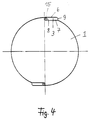
- wedges 3 show another embodiment of the wedges 3. These wedges are not made of feathers, but solid. They also have long pages 6 and 7 and short pages 8 and 9. However, the short side 8 is designed in the manner of a fillet and an elastic tube 15 is arranged between it and the opposite groove wall in the shaft.
Abstract
Description
Die Erfindung betrifft eine Vorrichtung zum Mischen und/oder Kneten von viskosen , plastischen , pulverförmigen oder körnigen Stoffen , bestehend aus einer in einer rohrförmigen Gehäuseöffnung angeordneten antreibbaren Schneckenwelle , welche aus einer das Drehmoment übertragenden Welle und einer Mehrzahl auf dieser hintereinander angeordneten und mittels wenigstens eines Keiles mit im wesentlichen rechteckigem Querschnitt drehfest mit dieser verbundenen Schneckenelementen als Teillastabnehmer besteht , bei der der Keil derart teils in der Welle und teils in den Schneckenelementen angeordnet ist , daß die langen Seiten des Keilquerschnitts parallel zur Tangente an den Wellenumfang und seine kurzen Seiten im rechten Winkel zu den langen Seiten angeordnet sind .The invention relates to a device for mixing and / or kneading viscous, plastic, powdery or granular substances, consisting of a drivable worm shaft arranged in a tubular housing opening, which consists of a shaft transmitting the torque and a plurality arranged one behind the other and by means of at least one Wedge with a substantially rectangular cross-section rotatably connected to this screw elements as a partial load, in which the wedge is arranged partly in the shaft and partly in the screw elements such that the long sides of the wedge cross section parallel to the tangent to the shaft circumference and its short sides in the right Angles to the long sides are arranged.
Eine solche Vorrichtung ist bekannt ( DE - C - 813 154 ). Das Ziel beim Kneten mit dieser Vorrichtung besteht darin, von der angetriebenen Welle eine möglichst große Energiemenge auf den in der Vorrichtung zu bearbeitenden Stoff zu übertragen , welche in ihm in Arbeit umgesetzt wird . Der Keil oder die Keile zwischen Welle und Schneckenelementen haben die Aufgabe, die Schneckenelemente in der richtigen Drehstellung auf der Welle zu positionieren und das Drehmoment während das Betriebs von der Welle über die Schneckenelemente in den zu bearbeitenden Werkstoff zu leiten.Such a device is known (DE - C - 813 154). The aim of kneading with this device is to transfer as much energy as possible from the driven shaft to the material to be processed in the device, which is converted into work in it. The wedge or wedges between the shaft and screw elements have the task of positioning the screw elements in the correct rotational position on the shaft and the torque during operation from the shaft via the screw elements in the material to be processed.
Bei der bekannten Vorrichtung tritt eine schwellende Torsionsbelastung der Welle in nur einer Richtung auf, welche diese auf Dauerfestigkeit beansprucht. Maßgebend für die Belastbarkeit der Welle ist die maximale Spannungskonzentration , welche in der Keilnut auftritt und deren maximal zulässiger Wert nicht überschritten werden darf. Der Keil bzw. die Keile sind in der Weise angeordnet , daß ihr Querschnitt radial und symmetrisch etwa je zur Hälfte in der Welle und in den Schneckenelementen liegt. Das hat einen gegen Kerbwirkung nicht optimal gestalteten Nutgrund und eine schlechte Zugänglichkeit der Nut zwecks Prüfung und Reinigung zur Folge.In the known device, a swelling torsional load of the shaft occurs in only one direction, which stresses it for fatigue strength. The maximum stress concentration that occurs in the keyway and whose maximum permissible value must not be exceeded is decisive for the load capacity of the shaft. The wedge or the wedges are arranged in such a way that their cross-section lies radially and symmetrically about half each in the shaft and in the screw elements. This results in a groove base that is not optimally designed against the notch effect and poor accessibility of the groove for testing and cleaning.
Das der Erfindung zugrunde liegende technischen Problem besteht deshalb darin , die Kopplung zwischen Welle und Schneckenelementen und die Leistungsfähigkeit der Welle in der Weise zu verbessern , daß das übertragbare Drehmoment ohne Vergrößerung der Abmessungen erhöht werden kann.The technical problem underlying the invention is therefore to improve the coupling between the shaft and screw elements and the performance of the shaft in such a way that the transmissible torque can be increased without increasing the dimensions.
Dieses technische Problem ist erfindungsgemäß durch folgende Anordnung des Keils gelöst :
- a) die zum Schneckenelement hin gerichtete lange Seite des Keilquerschnitts ist in etwa deckungsgleich mit der Tangente und liegt im wesentlichen im Schneckenelement,
- b) die zur Welle hin gerichtete lange Seite des Keilquerschnitts liegt im wesentlichen in der Welle ,
- c) die in zur Drehrichtung der Welle entgegengesetzten Richtung liegende kurze Seite des Keilquerschnitts liegt im wesentlichen in der Welle ,
- d) die in Drehrichtung der Welle liegende kurze Seite des Keiquerschnitts liegt im wesentlichen im Schneckenelement ,
- e) die in der Welle bzw. im Schneckenelement aneinanderstoßenden langen und kurzen Seiten sind im wesentlichen im rechten Winkel zueinander angeordnet und bilden eine offene , abgerundete Ecken aufweis ende Nut .
- a) the long side of the wedge cross section directed towards the screw element is approximately congruent with the tangent and lies essentially in the screw element,
- b) the long side of the wedge cross section directed towards the shaft lies essentially in the shaft,
- c) the short side of the wedge cross section lying in the direction opposite to the direction of rotation of the shaft lies essentially in the shaft,
- d) the short side of the kei section lying in the direction of rotation of the shaft lies essentially in the screw element,
- e) the long and short sides abutting in the shaft or in the screw element are arranged essentially at right angles to one another and form an open, rounded corners having groove.
Wenn der Keil oder die Keile in der erfindungsgemäßen Weise in der Welle und Schneckenelementen, d. h. tangential und asymmetrisch , angeordnet sind, dann kann bei gleichen Abmessungen mit der Welle ein wesentlich höheres Drehmoment übertragen werden , weil sich die rechnerische Sicherheit gegen Dauerbruch wesentlich erhöht.If the wedge or the wedges in the manner according to the invention in the shaft and screw elements, i. H. tangentially and asymmetrically, then a much higher torque can be transmitted with the shaft with the same dimensions, because the computational security against fatigue rises significantly.
Mit bei Druckbean spruchung federnden Keilen ergibt sich eine verbesserte radiale und axiale Lastaufteilung mit wenigstens zwei, in die gleich Drehrichtung wirkenden Keilen. Die derart verbesserte dreidimensionale Wirksamkeit vermindert die Flächenpressung wesentlich und erlaubt eine Verringerung des Flächenverbrauchs für die Keile .With resilient wedges under pressure, there is an improved radial and axial load distribution with at least two wedges acting in the same direction of rotation. The three-dimensional effectiveness improved in this way significantly reduces the surface pressure and permits a reduction in the space consumption for the wedges.
Es ist auch nicht mehr erforderlich , die Keile in der Welle mittels Preßsitz zu befestigen , sondern sie können mit geringem Spiel federnd zwischen Welle und Schneckenelementen eingeschoben werden. Das vereinfacht auch die spätere Demontage der Schneckenwelle . Ein weiterer Vorteil besteht darin , daß die Schneckenelemente wegen der asymmetrischen Lage der Keile nur in einer bestimmten Lage unverwechselbar auf der Welle aufgeschoben werden können .It is also no longer necessary to fix the wedges in the shaft by means of a press fit, but they can be inserted resiliently between the shaft and screw elements with little play. This also simplifies the later disassembly of the worm shaft. Another advantage is that the screw elements can be unmistakably pushed onto the shaft only in a certain position due to the asymmetrical position of the wedges.
Vorteilhafte Einzelheiten der Erfindung sind in den Ansprüchen 2 bis 6 enthalten . Sie ist nachstehend anhand der Figuren 1 bis 4 erläutert . Es zeigen :
- Fig. 1
- den prinzipiellen Aufbau einer Schneckenwellenmaschine im Querschnitt ,
- Fig. 2
- in vergrößerter Darstellung den Querschnitt der Welle mit den Heilen,
- Fig. 3a bis 3d
- verschiedene Ausführungsformen des Keils im Querschnitt und in der Draufsicht
- und Fig. 4
- den Querschnitt einer Welle mit einer anderen Ausführungsform der Keile .
- Fig. 1
- the basic structure of a worm shaft machine in cross section,
- Fig. 2
- in an enlarged view the cross section of the shaft with the healing,
- 3a to 3d
- different embodiments of the wedge in cross section and in plan view
- and Fig. 4
- the cross section of a shaft with another embodiment of the wedges.
Fig. 1 verdeutlicht den Querschnitt einer Schneckenwellenmaschine , welche aus der Welle 1 und mehreren hintereinander und in Umfangsrichtung gegeneinander versetzt angeordneten Schneckenelementen 2 besteht , von denen nur ein Schneckenelement gezeigt ist . Das Schneckenelement 2 ist durch die Keile 3 formschlüssig mit der Welle gekoppelt . Eine auf diese Weise gebildete Schneckenwelle ist drehbar in der kreisförmigen Innenbohrung des Gehäuses 4 angeordnet. Die Schneckenwellenmaschine kann auch so ausgebildet sein, daß sie mehrere Schneckenwellen besitzt , welches ein entsprechendes Gehäuse erforderlich macht. Wenn die Schneckenwellenmaschine zwei Schneckenwellen enthält , dann weist die Innenbohrung des Gehäuses die Form einer liegenden Acht auf. Die Schneckenwellen können entweder gegensinnig oder gleichsinnig angetrieben sein. In Fig. 1 zeigt der Pfeil 5 die Drehrichtung der Schneckenwelle an. Ein Betrieb in entgegengesetzter Drehrichtung ist nicht möglich.1 illustrates the cross section of a worm shaft machine which consists of the
Aus Fig. 2 ist die Lage des Keils oder der Heile 3 zu erkennen. Sie sind asymmetrisch zu einem gedachten Fadenkreuz am Umfang der Welle angeordnet. Jeder Keil weist in etwa einen rechteckigen Querschnitt auf ( von den abgerundeten Ecken abgesehen ), welcher eine äußere lange Seite 6 , eine innere lange Seite 7 und zwei kurze Seiten 8 und 9 aufweist. Wie aus Fig. 2 weiter zu erkennen , ist der Keil 3 derart in der Welle 1 und dem Schneckenelement 2 angeordnet , daß seine lange Seite 6 mit der Tangente 10 an den Wellenumfang deckungsgleich ist. Die lange Seite 7 des Keilquerschnitts ist parallel zur langen Seite 6 und die kurzen Seiten liegen rechtwinklig zu den langen Seiten .The position of the wedge or the
Bei der in Fig. 2 gezeigten Lage der Keile in der Welle und dem Schneckenelement handelt es sich um die optimale Ausführungsform. Die kurze Seite 8 taucht vollständig in die Welle 1 ein und die kurze Seite 9 taucht vollständig in das - in Fig. 2 nicht gezeigte - Schneckenelement ein. Daher werden die kurzen Seiten 8 und 9 des Keils im Betrieb nur auf Druck beansprucht.The position of the wedges in the shaft and the screw element shown in FIG. 2 is the optimal embodiment. The
Von der in Fig. 2 gezeigten optimalen Lage der Keile 3 kann in einem bestimmten Umfang ohne wesentliche Verschlechterung der Keilbeanspruchung abgewichen werden. Das könnte beispielsweise durch eine geringfügige Parallelverschiebung des Keils 3 nach außen und zur Seite geschehen.The optimal position of the
Die Figuren 3a bis 3 d zeigen verschiedene Ausführungsformen eines elastischen Keils 3. Bei der Ausführungsform gemäß Fig. 3 a sind in den Keil parallel zu den Längskanten verlaufende Längsnuten 11 eingebracht worden, von denen eine auf der Oberseite und eine auf der Unterseite des Keils offen ist.FIGS. 3a to 3d show different embodiments of an
Bei der Ausführungsform gemäß Fig. 3 b sind in dem Keil schräg verlaufende Schnitte 12 vorhanden.In the embodiment according to FIG. 3 b, oblique cuts 12 are present in the wedge.
Bei dem Ausführungsbeispiel gemäß Fig. 3 c verlaufen die Schnitte 13 parallel zu den Längskanten des Keils oder auch im rechten Winkel dazu.In the exemplary embodiment according to FIG. 3 c, the
Bei dem Ausführungsbeispiel gemäß Fig. 3 d liegen die Schnitte 14 nur parallel zu den Längsachsen des Keils , weisen jedoch eine andere Anordnung als in Fig. 3 c auf.In the embodiment according to FIG. 3 d, the
Fig. 4 zeigt eine andere Ausführungsform der Keile 3 . Diese Keile sind nicht federn , sondern massiv ausgebildet . Sie weisen auch lange Seiten 6 und 7 sowie kurze Seiten 8 und 9 auf . Jedoch ist die kurze Seite 8 in der Art einer Hohlkehle ausgebildet und zwischen ihr und der gegenüberliegenden Nutwand in der Welle ist ein elastisches Rohr 15 angeordnet .4 shows another embodiment of the
Claims (6)
gekennzeichnet durch folgende Anordnung des Keils :
characterized by the following arrangement of the wedge:
dadurch gekennzeichnet , daß der Querschnitt des Keils ( 3 ) ein Seitenverhältnis zwischen 1 : 3 und 1 : 6 aufweist .Device according to claim 1,
characterized in that the cross section of the wedge (3) has an aspect ratio between 1: 3 and 1: 6.
dadurch gekennzeichnet , daß zwei gleiche , in gleicher Richtung wirkende Keile ( 3 ) vorgesehen sind .Device according to claims 1 and 2,
characterized in that two identical wedges (3) acting in the same direction are provided.
dadurch gekennzeichnet , daß die Keile ( 3 ) federnd ausgebildet sind .Device according to claims 1 to 3,
characterized in that the wedges (3) are resilient.
dadurch gekennzeichnet , daß die Keile ( 3 ) mit Einschnitten und/oder Nuten ( 11,12,13,14 ) versehen sind.Device according to claims 1 to 4,
characterized in that the wedges (3) are provided with incisions and / or grooves (11, 12, 13, 14).
dadurch gekennzeichnet , daß zwischen der kurzen Seite ( 8 ) des Keils ( 3 ) und der ihr gegenüber liegenden Nutwand der Welle ( 1 ) ein elastisches Rohrstück (15 ) angeordnet ist.Device according to claim 1,
characterized in that an elastic tube piece (15) is arranged between the short side (8) of the wedge (3) and the groove wall of the shaft (1) lying opposite it.
Applications Claiming Priority (3)
| Application Number | Priority Date | Filing Date | Title |
|---|---|---|---|
| DE4206219A DE4206219A1 (en) | 1992-02-28 | 1992-02-28 | DEVICE FOR MIXING AND / OR KNOWING MATERIALS |
| DE4206219 | 1992-02-28 | ||
| US08/014,372 US5314245A (en) | 1992-02-28 | 1993-02-05 | Arrangement for mixing and kneading of materials with a screw shaft and at least one screw element connected with one another by wedges |
Publications (2)
| Publication Number | Publication Date |
|---|---|
| EP0557919A1 true EP0557919A1 (en) | 1993-09-01 |
| EP0557919B1 EP0557919B1 (en) | 1996-06-05 |
Family
ID=25912314
Family Applications (1)
| Application Number | Title | Priority Date | Filing Date |
|---|---|---|---|
| EP93102734A Expired - Lifetime EP0557919B1 (en) | 1992-02-28 | 1993-02-22 | Device for mixing and/or kneading materials |
Country Status (5)
| Country | Link |
|---|---|
| US (1) | US5314245A (en) |
| EP (1) | EP0557919B1 (en) |
| JP (1) | JP3176747B2 (en) |
| AT (1) | ATE138829T1 (en) |
| DE (2) | DE4206219A1 (en) |
Families Citing this family (6)
| Publication number | Priority date | Publication date | Assignee | Title |
|---|---|---|---|---|
| DE4421514C2 (en) * | 1994-06-20 | 1998-08-13 | Krupp Werner & Pfleiderer Gmbh | Screw machine with attachable screw set elements |
| US7188992B2 (en) * | 2003-07-30 | 2007-03-13 | Americhem, Inc. | Kneading element and related articles |
| US7192178B2 (en) * | 2004-02-19 | 2007-03-20 | J. C. Steele & Sons, Inc. | Extrusion auger with removable auger segments and removal tool |
| FR2971190B1 (en) * | 2011-02-09 | 2013-03-08 | Michelin Soc Tech | SCREWS FOR THE EXTRUSION OR MIXING OF ELASTOMERS OR PLASTIC PRODUCTS FOR THE MANUFACTURE OF TIRES |
| US20160061249A1 (en) * | 2014-08-29 | 2016-03-03 | Douglas H. Powell | Adjustable shear key |
| DE102015005790A1 (en) * | 2015-05-10 | 2016-11-10 | Reifenhäuser GmbH & Co. KG Maschinenfabrik | Screw for use in an extruder, method for converting a screw and extruder |
Citations (4)
| Publication number | Priority date | Publication date | Assignee | Title |
|---|---|---|---|---|
| DE813154C (en) * | 1949-09-29 | 1951-09-06 | Bayer Ag | Mixing and kneading device |
| US3155056A (en) * | 1959-08-26 | 1964-11-03 | American Mach & Foundry | Plastic or dough mixing apparatus |
| EP0001970A1 (en) * | 1977-11-12 | 1979-05-30 | Werner & Pfleiderer | Kneading rotor for screw extruders |
| EP0422272A1 (en) * | 1989-10-12 | 1991-04-17 | Josef A. Blach | Mixing and kneading device |
Family Cites Families (24)
| Publication number | Priority date | Publication date | Assignee | Title |
|---|---|---|---|---|
| US248400A (en) * | 1881-10-18 | Self-adjusting spline or key | ||
| US118474A (en) * | 1871-08-29 | Improvement in shaft-couplings | ||
| US732738A (en) * | 1901-12-02 | 1903-07-07 | Charles Hammen | Keys and key-seats for shafting. |
| US1460222A (en) * | 1922-05-26 | 1923-06-26 | Int Harvester Co | Machine key |
| FR567959A (en) * | 1922-09-08 | 1924-03-12 | Cie Forges Et Acieries Marine | Device for fixing the flywheels on their shaft |
| DE423465C (en) * | 1923-04-11 | 1926-01-04 | Bbc Brown Boveri & Cie | Fastening of turbine disks on their shaft by means of spring rings |
| DE609576C (en) * | 1933-09-19 | 1935-02-18 | Protectoglass Ltd | Device for producing shatterproof glass |
| US2681239A (en) * | 1950-08-16 | 1954-06-15 | James W Gillen | Pressure lock key |
| GB868469A (en) * | 1957-05-16 | 1961-05-17 | Huntley & Palmers Ltd | Improvements in continuously operable apparatus for kneading plastic masses |
| US2994548A (en) * | 1958-04-03 | 1961-08-01 | Donald H Mcgogy | Shaft keying device |
| FR1345563A (en) * | 1961-12-14 | 1963-12-13 | Improvement in tangential keying | |
| DE1180718B (en) * | 1962-04-11 | 1964-11-05 | Bayer Ag | Kneading device with two or more screws |
| FR1416667A (en) * | 1963-11-15 | 1965-11-05 | Wmb Internat Ab | Process for the manufacture of porous bodies in thermoplastic material |
| NL131340C (en) * | 1963-11-27 | 1900-01-01 | ||
| DE6604741U (en) * | 1966-02-11 | 1970-02-19 | Werner & Pfleiderer | SCREW MACHINE |
| US3421783A (en) * | 1967-08-30 | 1969-01-14 | Sakai Mfg Co Ltd | Shock-absorbing key for rotary body |
| GB1215057A (en) * | 1968-05-22 | 1970-12-09 | Laminated Plastic Products Ltd | Demountable agitator |
| DE2329514A1 (en) * | 1973-06-06 | 1975-01-02 | Mannesmann Meer Ag | Fixing large gears on converter-tilting shafts - using tapered journal and conical wedges on end of shaft |
| DE2617864A1 (en) * | 1976-04-23 | 1977-11-03 | Nosta Normteile Und Stahlkeile | Key for fixing wheels to shafts - has rounded ends to prevent damage to components during fitting and has square centre portion |
| SU724820A1 (en) * | 1978-09-06 | 1980-03-30 | Orenbojm Boris D | Key-type connection |
| US4358215A (en) * | 1980-10-20 | 1982-11-09 | Rivin Evgeny I | Key connection |
| DE3406665C2 (en) * | 1984-02-24 | 1986-10-23 | Fraunhofer-Gesellschaft zur Förderung der angewandten Forschung e.V., 8000 München | Screw extruder for processing explosives |
| US4875847A (en) * | 1984-04-23 | 1989-10-24 | Wenger Manufacturing, Inc. | Twin-screw extruder having respective conical nose screw sections |
| GB8804313D0 (en) * | 1988-02-24 | 1988-03-23 | Apv Plc | Improvements in/relating to mixers |
-
1992
- 1992-02-28 DE DE4206219A patent/DE4206219A1/en not_active Withdrawn
-
1993
- 1993-02-05 US US08/014,372 patent/US5314245A/en not_active Expired - Lifetime
- 1993-02-22 DE DE59302775T patent/DE59302775D1/en not_active Expired - Lifetime
- 1993-02-22 EP EP93102734A patent/EP0557919B1/en not_active Expired - Lifetime
- 1993-02-22 AT AT93102734T patent/ATE138829T1/en not_active IP Right Cessation
- 1993-02-25 JP JP03645993A patent/JP3176747B2/en not_active Expired - Fee Related
Patent Citations (4)
| Publication number | Priority date | Publication date | Assignee | Title |
|---|---|---|---|---|
| DE813154C (en) * | 1949-09-29 | 1951-09-06 | Bayer Ag | Mixing and kneading device |
| US3155056A (en) * | 1959-08-26 | 1964-11-03 | American Mach & Foundry | Plastic or dough mixing apparatus |
| EP0001970A1 (en) * | 1977-11-12 | 1979-05-30 | Werner & Pfleiderer | Kneading rotor for screw extruders |
| EP0422272A1 (en) * | 1989-10-12 | 1991-04-17 | Josef A. Blach | Mixing and kneading device |
Also Published As
| Publication number | Publication date |
|---|---|
| ATE138829T1 (en) | 1996-06-15 |
| DE59302775D1 (en) | 1996-07-11 |
| DE4206219A1 (en) | 1993-09-02 |
| EP0557919B1 (en) | 1996-06-05 |
| JPH07251053A (en) | 1995-10-03 |
| JP3176747B2 (en) | 2001-06-18 |
| US5314245A (en) | 1994-05-24 |
Similar Documents
| Publication | Publication Date | Title |
|---|---|---|
| EP0422272B1 (en) | Mixing and kneading device | |
| DE2360440C3 (en) | Track chain link | |
| DE3044415A1 (en) | ELASTIC COUPLING FOR TRANSMITTING A ROTATING MOTION | |
| DE3032537C2 (en) | ||
| DE3417555C2 (en) | ||
| EP0557919B1 (en) | Device for mixing and/or kneading materials | |
| EP0318669B1 (en) | Flexible coupling with spring discs | |
| DE2542321A1 (en) | COUPLING ARRANGEMENT FOR DYNAMOELECTRIC MACHINE | |
| DE2655728C2 (en) | Detachable hub-shaft connection | |
| EP3234389B1 (en) | Clutch element and clutch arrangement for the axial transmission of torque, and multiple disc arrangement therefor | |
| EP0013274A1 (en) | Mechanical connectors and fixing tool therefor | |
| DE3828131C2 (en) | ||
| DE19732663A1 (en) | Torque transmission without backlash | |
| EP0178537B1 (en) | Method for fitting drive elements on a shaft by means of axially cutting splines, and these elements as such | |
| DE2125659B2 (en) | SEALING BOLTS IN CIRCULAR RECESSES IN THE FACE WALLS OF PISTON PARALLEL AND INAXIAL ROTARY PISTON MACHINES WITH SLIP ENGAGEMENT | |
| DE3024004A1 (en) | SHAFT COUPLING | |
| CH672906A5 (en) | ||
| DE2534135C3 (en) | Claw coupling with elastic cushions | |
| DE3013957A1 (en) | DIE CHANGING DEVICE | |
| DE2601388A1 (en) | Reamed bolt for machined plates - has two rotating eccentrics and sleeves to adapt to position of through holes | |
| EP0273172B1 (en) | Feed roll for work pieces of wood, materials similar to wood or plastic | |
| WO2002066849A1 (en) | Flange driver | |
| DE2807120C2 (en) | Hob with inserted cutting edges | |
| DE2156030A1 (en) | Sprocket set | |
| DE2849780C2 (en) |
Legal Events
| Date | Code | Title | Description |
|---|---|---|---|
| PUAI | Public reference made under article 153(3) epc to a published international application that has entered the european phase |
Free format text: ORIGINAL CODE: 0009012 |
|
| AK | Designated contracting states |
Kind code of ref document: A1 Designated state(s): AT BE CH DE ES FR GB IT LI NL |
|
| 17P | Request for examination filed |
Effective date: 19931221 |
|
| 17Q | First examination report despatched |
Effective date: 19941208 |
|
| GRAA | (expected) grant |
Free format text: ORIGINAL CODE: 0009210 |
|
| AK | Designated contracting states |
Kind code of ref document: B1 Designated state(s): AT BE CH DE ES FR GB IT LI NL |
|
| PG25 | Lapsed in a contracting state [announced via postgrant information from national office to epo] |
Ref country code: NL Free format text: LAPSE BECAUSE OF FAILURE TO SUBMIT A TRANSLATION OF THE DESCRIPTION OR TO PAY THE FEE WITHIN THE PRESCRIBED TIME-LIMIT Effective date: 19960605 Ref country code: ES Free format text: THE PATENT HAS BEEN ANNULLED BY A DECISION OF A NATIONAL AUTHORITY Effective date: 19960605 |
|
| REF | Corresponds to: |
Ref document number: 138829 Country of ref document: AT Date of ref document: 19960615 Kind code of ref document: T |
|
| REF | Corresponds to: |
Ref document number: 59302775 Country of ref document: DE Date of ref document: 19960711 |
|
| ET | Fr: translation filed | ||
| GBT | Gb: translation of ep patent filed (gb section 77(6)(a)/1977) |
Effective date: 19960626 |
|
| GRAH | Despatch of communication of intention to grant a patent |
Free format text: ORIGINAL CODE: EPIDOS IGRA |
|
| ITF | It: translation for a ep patent filed |
Owner name: STUDIO JAUMANN |
|
| NLV1 | Nl: lapsed or annulled due to failure to fulfill the requirements of art. 29p and 29m of the patents act | ||
| PG25 | Lapsed in a contracting state [announced via postgrant information from national office to epo] |
Ref country code: LI Effective date: 19970228 Ref country code: CH Effective date: 19970228 Ref country code: BE Effective date: 19970228 |
|
| PLBE | No opposition filed within time limit |
Free format text: ORIGINAL CODE: 0009261 |
|
| STAA | Information on the status of an ep patent application or granted ep patent |
Free format text: STATUS: NO OPPOSITION FILED WITHIN TIME LIMIT |
|
| 26N | No opposition filed | ||
| PGFP | Annual fee paid to national office [announced via postgrant information from national office to epo] |
Ref country code: AT Payment date: 19970801 Year of fee payment: 5 |
|
| REG | Reference to a national code |
Ref country code: CH Ref legal event code: PL |
|
| PGFP | Annual fee paid to national office [announced via postgrant information from national office to epo] |
Ref country code: GB Payment date: 19980212 Year of fee payment: 6 |
|
| PG25 | Lapsed in a contracting state [announced via postgrant information from national office to epo] |
Ref country code: AT Free format text: LAPSE BECAUSE OF NON-PAYMENT OF DUE FEES Effective date: 19980222 |
|
| PG25 | Lapsed in a contracting state [announced via postgrant information from national office to epo] |
Ref country code: GB Free format text: LAPSE BECAUSE OF NON-PAYMENT OF DUE FEES Effective date: 19990222 |
|
| PGFP | Annual fee paid to national office [announced via postgrant information from national office to epo] |
Ref country code: FR Payment date: 19990226 Year of fee payment: 7 |
|
| GBPC | Gb: european patent ceased through non-payment of renewal fee |
Effective date: 19990222 |
|
| PG25 | Lapsed in a contracting state [announced via postgrant information from national office to epo] |
Ref country code: FR Free format text: LAPSE BECAUSE OF NON-PAYMENT OF DUE FEES Effective date: 20001031 |
|
| REG | Reference to a national code |
Ref country code: FR Ref legal event code: ST |
|
| PG25 | Lapsed in a contracting state [announced via postgrant information from national office to epo] |
Ref country code: IT Free format text: LAPSE BECAUSE OF NON-PAYMENT OF DUE FEES;WARNING: LAPSES OF ITALIAN PATENTS WITH EFFECTIVE DATE BEFORE 2007 MAY HAVE OCCURRED AT ANY TIME BEFORE 2007. THE CORRECT EFFECTIVE DATE MAY BE DIFFERENT FROM THE ONE RECORDED. Effective date: 20050222 |
|
| PGFP | Annual fee paid to national office [announced via postgrant information from national office to epo] |
Ref country code: DE Payment date: 20120222 Year of fee payment: 20 |
|
| REG | Reference to a national code |
Ref country code: DE Ref legal event code: R071 Ref document number: 59302775 Country of ref document: DE |
|
| PG25 | Lapsed in a contracting state [announced via postgrant information from national office to epo] |
Ref country code: DE Free format text: LAPSE BECAUSE OF EXPIRATION OF PROTECTION Effective date: 20130223 |