EP0557579B1 - Dichtungsanordnung - Google Patents
Dichtungsanordnung Download PDFInfo
- Publication number
- EP0557579B1 EP0557579B1 EP92117666A EP92117666A EP0557579B1 EP 0557579 B1 EP0557579 B1 EP 0557579B1 EP 92117666 A EP92117666 A EP 92117666A EP 92117666 A EP92117666 A EP 92117666A EP 0557579 B1 EP0557579 B1 EP 0557579B1
- Authority
- EP
- European Patent Office
- Prior art keywords
- sealing
- ring
- housing
- rod
- arrangement according
- Prior art date
- Legal status (The legal status is an assumption and is not a legal conclusion. Google has not performed a legal analysis and makes no representation as to the accuracy of the status listed.)
- Expired - Lifetime
Links
- 238000007789 sealing Methods 0.000 title claims abstract description 137
- 230000033001 locomotion Effects 0.000 claims abstract description 11
- 239000002861 polymer material Substances 0.000 claims abstract 2
- 239000004810 polytetrafluoroethylene Substances 0.000 claims description 4
- 229920001343 polytetrafluoroethylene Polymers 0.000 claims description 4
- 230000006835 compression Effects 0.000 abstract description 17
- 238000007906 compression Methods 0.000 abstract description 17
- 238000006073 displacement reaction Methods 0.000 description 3
- 239000000463 material Substances 0.000 description 3
- 239000013536 elastomeric material Substances 0.000 description 2
- 238000004519 manufacturing process Methods 0.000 description 2
- 239000007769 metal material Substances 0.000 description 2
- 239000004033 plastic Substances 0.000 description 2
- 239000011248 coating agent Substances 0.000 description 1
- 238000000576 coating method Methods 0.000 description 1
- 238000013016 damping Methods 0.000 description 1
- 230000000694 effects Effects 0.000 description 1
- 230000036316 preload Effects 0.000 description 1
- 230000000750 progressive effect Effects 0.000 description 1
Images
Classifications
-
- F—MECHANICAL ENGINEERING; LIGHTING; HEATING; WEAPONS; BLASTING
- F16—ENGINEERING ELEMENTS AND UNITS; GENERAL MEASURES FOR PRODUCING AND MAINTAINING EFFECTIVE FUNCTIONING OF MACHINES OR INSTALLATIONS; THERMAL INSULATION IN GENERAL
- F16J—PISTONS; CYLINDERS; SEALINGS
- F16J15/00—Sealings
- F16J15/16—Sealings between relatively-moving surfaces
- F16J15/32—Sealings between relatively-moving surfaces with elastic sealings, e.g. O-rings
- F16J15/3204—Sealings between relatively-moving surfaces with elastic sealings, e.g. O-rings with at least one lip
- F16J15/3224—Sealings between relatively-moving surfaces with elastic sealings, e.g. O-rings with at least one lip capable of accommodating changes in distances or misalignment between the surfaces, e.g. able to compensate for defaults of eccentricity or angular deviations
-
- F—MECHANICAL ENGINEERING; LIGHTING; HEATING; WEAPONS; BLASTING
- F16—ENGINEERING ELEMENTS AND UNITS; GENERAL MEASURES FOR PRODUCING AND MAINTAINING EFFECTIVE FUNCTIONING OF MACHINES OR INSTALLATIONS; THERMAL INSULATION IN GENERAL
- F16J—PISTONS; CYLINDERS; SEALINGS
- F16J15/00—Sealings
- F16J15/16—Sealings between relatively-moving surfaces
- F16J15/32—Sealings between relatively-moving surfaces with elastic sealings, e.g. O-rings
- F16J15/3204—Sealings between relatively-moving surfaces with elastic sealings, e.g. O-rings with at least one lip
- F16J15/3216—Sealings between relatively-moving surfaces with elastic sealings, e.g. O-rings with at least one lip supported in a direction parallel to the surfaces
Definitions
- the invention relates to a sealing arrangement for sealing a reciprocating rod relative to a housing enclosing the rod at a radial distance, the sealing arrangement containing a sealing ring made of polymeric material, which is provided with a radially movable sealing lip and is received in a sealing housing, an auxiliary sealing lip is provided, with which the housing can be brought into engagement by the force of a compression spring effective in the axial direction and the sealing ring is supported on the rod by a guide ring and the auxiliary sealing lip forms an integral part of the sealing ring.
- Such a sealing arrangement is known from EP-A-0 032 988.
- the known sealing arrangement is provided for sealing a piston rod of telescopic vibration dampers, the piston rod being axially displaceable and radially movable relative to the damper housing.
- the sealing arrangement is provided with a sleeve which has a sealing lip, the sleeve being guided in radial movements of the piston rod by a support ring guided without play on the piston rod.
- the support ring consists of a plain bearing material to ensure the function of the seal even at particularly low temperatures.
- the piston rod seal shown therein has an outer sealing element which is permanently installed in the radial direction and surrounds the piston rod, and an inner sealing element which also prestresses the piston rod encloses and is floating, so that it can follow radial movements of the piston rod to be sealed.
- a compression spring which acts in the axial direction acts axially on the inner sealing element in the direction of the outer sealing element, so that a tight connection is thereby formed.
- the inner sealing element forms the axial support of the compression spring.
- the invention has for its object to further develop a seal assembly of the known type such that a low-friction displacement of the seal in radial direction in the sealing of pressurized media ensures that comfort-impairing stop noises caused by striking the guide ring on the housing are avoided and that the sealing arrangement is easy to manufacture and assemble.
- the sealing ring has an integrally formed stop buffer for limiting radial deflection movements in the direction of the seal housing and that the stop buffer has a radial distance from the seal housing that is 0.2 to 0.8 times as large as a radial gap that the guide ring delimits with a housing projection.
- the guide ring is arranged on the side of the sealing ring facing away from the medium to be sealed and is placed against a stop surface of the housing.
- the axial force exerted by the media pressure on the seal is essentially absorbed by the support ring, which is made of a slidable plastic.
- the earlier striking of the stop buffer on the seal housing based on the striking of the guide ring on the housing projection has the advantage that extreme deflection movements of the rod with the sealing sealing ring are gradually and resiliently intercepted when the stop buffer touches the seal housing.
- the progressive damping characteristics of the impact buffer prevent impact-impairing impact noises. Only in extreme cases, which can be virtually excluded in normal operation, does the guide ring come into contact with the projection on the housing.
- the guide ring can consist of a slidable plastic, preferably of PTFE, and can be buttoned into the sealing ring.
- the support ring therefore does not form a component to be assembled separately or to be fixed in the housing bore, but can be buttoned into the sealing ring before the actual assembly and assembled together with it.
- the guide ring can, for example, be buttoned into the sealing ring.
- the sealing ring and the guide ring are adhesively connected. Regardless of the radial deflections of the sealing ring, it is supported by the guide ring.
- the Guide ring which is preferably made of PTFE, can be reinforced to extend its service life. This is particularly useful when the guide ring is buttoned into the sealing ring and is to be used again when the sealing ring is replaced.
- the sealing lip and the auxiliary sealing lip are formed by converging sealing surfaces which enclose a larger angle with the surfaces to be sealed on the side facing the medium to be sealed than on the side facing away from the medium.
- This configuration of the sealing lips is particularly advantageous in the case of the dynamically sealing sealing lip.
- the rod to be sealed moves axially in one direction with a greater wiping action than in the other. This has the effect that, in particular in connection with radial deflections of the rod to be sealed, components of the medium to be sealed that have already passed the dynamic sealing lip are taken back in the direction of the space to be sealed when the direction of movement of the rod to be sealed is reversed.
- An annular helical spring can be assigned to the sealing lip, so that a good sealing result of the axially movable rod to be sealed is ensured both at low pressurization and at high pressurization.
- a stiffening ring is provided which is at least partially enclosed by the sealing ring material, the compression spring only touching the stiffening ring.
- the compression spring is supported on the one hand in the seal housing, which preferably consists of metallic material, and on the other hand on the stiffening ring, which is also mostly made of metallic material. In the case of relative movements between the sealing ring and the compression spring or the compression spring and the seal housing, wear and / or damage to the parts in contact with one another is thereby excluded.
- the surfaces in contact with one another can be provided, for example, with a friction-reducing surface coating, as a result of which the mechanical loads are reduced in particular to the dynamically sealing sealing lip in the event of radial deflections of the rod to be sealed.
- the sealing ring is then able to follow deflection movements of the rod in a particularly good manner and the good properties of use remain almost unchanged over a particularly long period of use.
- the compression spring can be formed, for example, by a plate spring.
- the expansion of the sealing arrangement in the axial direction is particularly small and in this case with a corresponding arrangement of the plate spring in the axial direction between the stiffening ring and the seal housing, the spring forces of the plate spring, which can be changed with a variable spring travel, can be advantageously used in the axial direction.
- the compression spring can also be designed as a helical compression spring, for example, which can be guided on the side facing the seal through a projection made of elastomeric material, which is integrally formed on the sealing ring.
- the axial preload force of the compression spring is to be dimensioned such that it is greater than the axial frictional force on the sealing lip of the sealing ring when the rod to be sealed is axially displaced. A sufficiently large contact pressure of the auxiliary sealing lip on the surface of the housing to be sealed is guaranteed at all times.
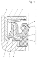
- FIG. 1 an embodiment of the sealing arrangement according to the invention is shown in a sectional view, which is suitable for sealing medium pressurized with up to 120 bar, the sealing housing 4, the sealing ring 2, the compression spring 6, which is designed in this case as a plate spring, and receives the guide ring 7 and into a bore in the housing 1 is inserted.
- the seal housing 4 has an essentially U-shaped profile which is open in the direction of the rod (not shown here) and surrounds the sealing ring 2 at a radial distance.
- the seal housing 4 encloses the sealing ring 2 such that the stop buffer 9, which extends essentially in the radial direction and is formed in one piece with the sealing ring 2, before assembly in the axial direction on the adjacent, radially inwardly facing leg of the U-shaped profile.
- the sealing housing 4 is brought to bear against a housing projection in the axial direction.
- the stop buffer 9 is then at an axial distance from the seal housing 4, so that the sealing ring 2 only bears in the axial direction in the area of the quasi-statically loaded auxiliary sealing lip 5 on the housing 1.
- the guide ring 7 is buttoned into the sealing ring and adhesively connected to it.
- the spring force applied to the auxiliary sealing lip 5 is variable during radial deflection movements of the sealing ring 2.
- a similarly configured sealing arrangement could also be designed as a cassette seal.
- the auxiliary sealing lip 5 would be supported on a radially inwardly directed leg of the sealing housing.
- the seal housing 4 would have to be additionally sealed with respect to the housing 1, which necessitates an increased production outlay.
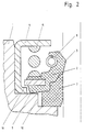
- the sealing arrangement from FIG. 2 is very similar to the sealing arrangement from FIG. 1.
- a helical spring is used as the compression spring 6, which is arranged in the axial direction on the one hand on the sealing housing 4 and on the other hand on a stiffening ring 11 extending in the radial direction.
- the auxiliary sealing lip 5 touches the housing 1 in a sealing manner.
- both the sealing ring 2 and the guide ring 7, which are fixed to one another, are displaced in the same way in the radial direction.
- the support ring 7 is preferably made of PTFE.
- the entire sealing arrangement adapts very well to the radial deflection movements of the rod to be sealed.
- the sealing arrangement is preferably used to seal high pressures.
- the axial force that the medium to be sealed exerts on the sealing arrangement is essentially absorbed by the guide ring 7, which is arranged in the recess in the axial direction of the housing 1 and is supported thereon.
Landscapes
- Engineering & Computer Science (AREA)
- General Engineering & Computer Science (AREA)
- Mechanical Engineering (AREA)
- Sealing With Elastic Sealing Lips (AREA)
- Materials For Medical Uses (AREA)
- Sealing Battery Cases Or Jackets (AREA)
- Glass Compositions (AREA)
- Fluid-Damping Devices (AREA)
- Sealing Devices (AREA)
- Sealing Material Composition (AREA)
Description
- Die Erfindung betrifft eine Dichtungsanordnung zur Abdichtung einer hin- und herbewegbaren Stange gegenüber einem die Stange in radialem Abstand umschließenden Gehäuse, wobei die Dichtungsanordnung einen Dichtring aus polymerem Werkstoff enthält, der mit einer radial beweglichen Dichtlippe versehen und in einem Dichtungsgehäuse aufgenommen ist, wobei eine Hilfsdichtlippe vorgesehen ist, mit der das Gehäuse durch die Kraft einer in axialer Richtung wirksamen Druckfeder in Eingriff bringbar ist und wobei der Dichtring durch einen Führüngsring auf der Stange abgestützt ist und die Hilfsdichtlippe einen einstückigen Bestandteil des Dichtringes bildet.
- Eine solche Dichtungsanordnung ist aus der EP-A- 0 032 988 bekannt. Die vorbekannte Dichtungsanordnung ist zur Abdichtung einer Kolbenstange von Teleskop-Schwingungsdämpfern vorgesehen, wobei die Kolbenstange gegenüber dem Dämpfergehäuse axial verschieblich und radial beweglich ist. Die Dichtungsanordnung ist mit einer Manschette versehen, die eine Dichtlippe aufweist, wobei die Manschette von einem spielfrei auf der Kolbenstange geführten Stützring in radialen Bewegungen der Kolbenstange nachgeführt wird. Der Stützring besteht aus einem Gleitlagerwerkstoff um die Funktion der Dichtung auch bei besonders tiefen Temperaturen zu gewährleisten.
- Eine weitere Dichtungsanordnung ist aus der DE-AS 30 19 736 bekannt. Die darin gezeigte Kolbenstangendichtung weist ein in radialer Richtung fest eingebautes, die Kolbenstange umschließendes äußeres Dichtelement auf und ein inneres Dichtelement, das die Kolbenstange ebenfalls mit Vorspannung umschließt und schwimmend gelagert ist, so daß es Radialbewegungen der abzudichtenden Kolbenstange zu folgen vermag. Eine in axiale Richtung wirksame Druckfeder beaufschlagt das innere Dichtelement axial in Richtung des äußeren Dichtelements so daß dadurch eine dichte Verbindung gebildet ist. Das innere Dichtelement bildet die axiale Abstützung der Druckfeder. Dabei ist allerdings zu beachten, daß die vorbekannte Dichtungsvorrichtung zum Abdichten von druckbeaufschlagten Medien aufgrund des dann auftretenden, hohen Verschleißes wenig geeignet ist. Außerdem ist die Dichtung aus zwei separat zu erzeugenden Dichtringen gebildet, wodurch sich eine wenig befriedigende Herstellbarkeit der Dichtungsanordnung und eine schwierige Montage ergeben.
- Der Erfindung liegt die Aufgabe zugrunde, eine Dichtungsanordnung der vorbekannten Art derart weiterzuentwickeln, daß eine reibungsarme Verschiebbarkeit der Dichtung in radialer Richtung bei der Abdichtung druckbeaufschlagter Medien gewährleistet ist, daß komfortbeeinträchtigende Anschlaggeräusche die durch ein Anschlagen des Führungsrings am Gehäuse verursacht werden, vermiden werden und daß die Dichtungsanordnung einfach herstellbar und montierbar ist.
- Diese Aufgabe wird erfindungsgemäß mit den kennzeichnenden Merkmalen von Anspruch 1 gelöst. Auf vorteilhafte Ausgestaltungen nehmen die Unteransprüche Bezug.
- Zur Lösung der Aufgabe ist es vorgesehen, daß dem Dichtring eine einstückig angeformter Anschlagpuffer zur Begrenzung von radialen Auslenkbewergungen in Richtung des Dichtungsgehäuses zugeordnet ist und daß der Anschlagpuffer einen radialen Abstand vom Dichtungsgehäuse aufweist, der 0,2 bis 0,8 mal so groß ist wie ein radialer Spalt, den der Führungsring mit einem Gehäusevorsprung begrenzt. Durch die Abstützung des Dichtringes auf dem Führungsring ist der Verschleiß der Dichtlippen deutlich reduziert und die Dichtungsanordnung weist gute Gebrauchseigenschaften während einer langen Gebrauchsdauer auf. Ein wechseln der Dichtungsanordnung ist durch die einstückige Ausbildung des Dichtringes, an dem sowohl die Dichtlippe als auch die Hilfsdichtlippe einstückig angeformt ist, wesentlich vereinfacht. Außerdem ist die Gefahr von montagebedingten Beschädigungen durch die einfache Ausgestaltung der Dichtungsanordnung wesentlich reduziert. Einer besonders genauen Zuordnung der von der Dichtungsanordnung umfaßten Teile zueinander ist nicht nötig. Im Rahmen der vorliegenden Erfindung ist es vorgesehen, daß der Führungsring auf der von dem abzudichtenden Medium abgewandten Seite des Dichtringes angeordnet und an eine Anschlagfläche des Gehäuses angelegt ist. Die vom Mediendruck auf die Dichtung ausgeübte Axialkraft wird dadurch im wesentlichen von dem aus einem gleitfähigen Kunststoff bestehenden Stützring aufgenommen.
- Die mechanischen Belastungen auf den Dichtring aus elastomeren Werkstoff sind dadurch reduziert. Weniger Verschleiß, bessere Gebrauchseigenschaften und eine längere Gebrauchsdauer werden dadurch bedingt, sowie eine außerordentlich reibungsarme Verschiebbarkeit der Dichtung in radialer Richtung. Eine hohe Druckbeaufschlagung des abzudichtenden Mediums hat im wesentlichen keinen Einfluß auf die guten Gebrauchseigenschaften.
- Das frühere Anschlagen des Anschlagpuffers am Dichtungsgehäuse bezogen auf das Anschlagen des Führungsringes am Gehäusevorsprung hat den Vorteil, daß extreme Auslenkbewegungen der Stange mit dem abdichtenden Dichtring bei Berührung des Anschlagpuffers an dem Dichtungsgehäuse allmählich und federnd abgefangen werden.
- Die progressive Dämpfungscharakteristik des Anschlagpuffers verhindert komfortbeeinträchtigende Anschlaggeräusche. Nur in Extremfällen, die im normalen Betrieb so gut wie auszuschließen sind, erfolgt eine Anschlagberührung des Führungsringes an dem Gehäusevorsprung.
- Gemäß einer vorteilhaften Ausgestaltung ist es vorgesehen, daß der Führungsring aus einem gleitfähigen Kunststoff, bevorzugt aus PTFE bestehen kann und in den Dichtring einknöpfbar ist. Der Stützring bildet demnach kein separat zu montierendes oder in der Gehäusebohrung festzulegendes Baute, sondern er kann bereits vor der eigentlichen Montage in den Dichtring eingeknöpft werden und gemeinsam mit diesem montiert werden. Der Führungsring kann beispielsweise formschlüssig in den Dichtring eingeknöpft sein.
- Zusätzlich oder alternativ besteht die Möglichkeit, daß der Dichtring und der Führungsring adhäsiv verbunden sind. Unabhängig von den radialen Auslenkungen des Dichtringes wird dieser durch den Führungsring gestützt. Der Führungsring, der bevorzugt aus PTFE besteht, kann zur Verlängerung seiner Gebrauchsdauer verstärkt sein. Dies bietet sich insbesondere dann an, wenn der Führungsring eingeknöpft in dem Dichtring gehalten wird und bei einem Austausch des Dichtringes wieder verwendet werden soll.
- Hinsichtlich einer guten Abdichtung des abzudichtenden Mediums ist es vorgesehen, daß die Dichtlippe und die Hilfsdichtlippe durch konvergierende Dichtflächen gebildet sind, die auf der dem abzudichtenden Medium zugewandten Seite einen größeren Winkel mit den abzudichtenden Flächen einschließen, als auf der dem Medium abgewandten Seite.
- Diese Ausgestaltung der Dichtlippen ist insbesondere bei der dynamisch abdichtenden Dichtlippe von Vorteil. In Abhängigkeit von den jeweiligen Gegebenheiten des Anwendungsfalles ergibt sich bei axialer Bewegung der abzudichtenden Stange in die eine Richtung eine größere Abstreifwirkung als in die andere. Dadurch wird bewirkt, daß insbesondere in Verbindung mit auftretenden Radialauslenkungen der abzudichtenden Stange Bestandteile des abzudichtenden Mediums, die die dynamische Dichtlippe bereits passiert haben bei Umkehr der Bewegungsrichtung der abzudichtenden Stange wieder in Richtung des abzudichtenden Raumes mitgenommen werden.
- Der Dichtlippe kann eine Ringwendelfeder zugeordnet sein, so daß ein gutes Abdichtungsergebnis der abzudichtenden, axial beweglichen Stange sowohl bei niedriger Druckbeaufschlagung als auch bei hoher Druckbeaufschlagung sichergestellt ist.
- Zur Stabilisierung des Dichtringes ist ein Versteifungsring vorgesehen, der zumindest teilweise von Dichtring-Werkstoff umschlossen ist, wobei die Druckfeder nur den Versteifungsring anliegend berührt. Nach dieser Ausgestaltung ist die Druckfeder einerseits im Dichtungsgehäuse, das bevorzugt aus metallischem Werkstoff besteht, abgestützt und andererseits an dem ebenfalls zumeist aus metallischem Werkstoff bestehenden Versteifungsring. Bei Relativbewegungen zwischen dem Dichtring und der Druckfeder oder der Druckfeder und dem Dichtungsgehäuse ist dadurch Verschleiß und/oder eine Beschädigung der einander berührenden Teile ausgeschlossen. Die einander berührenden Flächen können beispielsweise mit einer reibungsverringernden Oberflächenbeschichtung versehen sein, wodurch die mechanischen Belastungen insbesondere auf die dynamisch abdichtende Dichtlippe bei Radialauslenkungen der abzudichtenden Stange reduziert sind. Der Dichtring vermag Auslenkbewegungen der Stange dann in besonders guter Weise zu folgen und die guten Gebrauchseigenschaften bleiben während einer besonders langen Gebrauchsdauer nahezu unverändert erhalten.
- Die Druckfeder kann beispielsweise durch eine Tellerfeder gebildet sein. Die Ausdehnung der Dichtungsanordnung in axialer Richtung ist in diesem Falle besonders gering und
bei entsprechender Anordnung der Tellerfeder in axialer Richtung zwischen dem Versteifungsring und dem Dichtungsgehäuse können die sich mit veränderlichem Federweg veränderbaren Federkräfte der Tellerfeder in axialer Richtung vorteilhaft genutzt werden. Nach einer anderen Ausgestaltung kann die Druckfeder beispielsweise auch als Schraubendruckfeder ausgebildet sein, wobei diese auf der der Dichtung zugewandten Seite durch einen Vorsprung aus elastomerem Werkstoff geführt sein kann, der einstückig an den Dichtring angeformt ist. - Die axiale Vorspannkraft der Druckfeder ist so zu bemessen, daß diese größer ist, als die axiale Reibkraft auf die Dichtlippe des Dichtringes bei axialer Verschiebung der abzudichtenden Stange. Ein ausreichend großer Anpreßdruck der Hilfsdichtlippe an die abzudichtende Fläche des Gehäuses ist dadurch jederzeit gewährleistet.
- Die Dichtungsanordnung der vorliegenden Erfindung wird nachfolgend anhand der in der Anlage beigefügten Zeichnungen weiter beschrieben. Es zeigen:
- Figur 1 eine Dichtungsanordnung, bei der die Druckfeder als Tellerfeder ausgebildet ist,
- Figur 2 eine Dichtungsanordnung, ähnlich wie die Dichtungsanordnung aus Figur 1, wobei die Druckfeder durch eine Schraubendruckfeder gebildet wird.
- In Figur 1 ist ein Ausführungsbeispiel der erfindungsgemäßen Dichtungsanordnung in geschnittener Darstellung gezeigt, die zum Abdichten von mit bis zu 120 bar druckbeaufschlagtem Medium geeignet ist, wobei das Dichtungsgehäuse 4 den Dichtring 2, die Druckfeder 6, die in diesem Falle als Tellerfeder ausgebildet ist, und den Führungsring 7 aufnimmt und in eine Bohrung des Gehäuses 1 eingesetzt ist. Das Dichtungsgehäuse 4 weist ein im wesentlichen U-förmiges, in Richtung der hier nicht dargestellten Stange geöffnetes Profil auf und umschließt den Dichtring 2 mit radialem Abstand. Zur Erleichterung der Montage umschließt das Dichtungsgehäuse 4 den Dichtring 2 derart, daß der Anschlagpuffer 9, der sich im wesentlichen in radialer Richtung erstreckt und einstückig mit dem Dichtring 2 ausgebildet ist, vor der Montage in axialer Richtung an dem benachbarten, radial nach innen weisenden Schenkel des U-förmigen Profils anliegt. Nach der Montage der Dichtungsanordnung in das Gehäuse, die durch axiales Einschieben in die Bohrung des Gehäuses 1 erfolgt, ist das Dichtungsgehäuse 4 in axialer Richtung an einem Gehäusevorsprung zur Anlage gebracht. Der Anschlagpuffer 9 weist dann einen axialen Abstand vom Dichtungsgehäuse 4 auf, so daß der Dichtring 2 in axialer Richtung nur noch im Bereich der quasi statisch belasteten Hilfsdichtlippe 5 am Gehäuse 1 dichtend anliegt. Der Führungsring 7 ist in dem hier dargestellten Ausführungsbeispiel in den Dichtring eingeknöpft und mit diesem adhäsiv verbunden. Durch die Abstützung der Tellerfeder einerseits im Dichtungsgehäuse 4 und andererseits an der Begrenzungskante des Versteifungsringes 11, ist die Federkraftbeaufschlagung der Hilfsdichtlippe 5 bei radialen Auslenkbewegungen des Dichtringes 2 veränderlich. Eine ähnlich ausgestaltete Dichtungsanordnung könnte auch als Kassettendichtung ausgebildet sein. Die Hilfsdichtlippe 5 würde sich in diesem Falle an einem radial nach innen gerichteten Schenkel des Dichtungsgehäuses abstützen. Hierbei wäre allerdings von Nachteil, daß das Dichtungsgehäuse 4 gegenüber dem Gehäuse 1 zusätzlich abgedichtet werden müßte, was einen vergrößerten Herstellungsaufwand bedingt.
- Die Dichtungsanordnung aus Figur 2 ist der Dichtungsanordnung aus Figur 1 sehr ähnlich. Anstelle einer Tellerfeder gelangt als Druckfeder 6 eine Schraubenfeder zur Anwendung, die in axialer Richtung einerseits am Dichtungsgehäuse 4 und andererseits an einem sich in radialer Richtung erstreckenden Versteifungsring 11 angeordnet ist. Auch in diesem Ausführungsbeispiel berührt die Hilfsdichtlippe 5 das Gehäuse 1 dichtend anliegend. Bei radialen Verlagerungen der hier nicht dargestellten Stange verlagern sich sowohl der Dichtring 2 als auch der Führungsring 7, die aneinander festgelegt sind, in gleicher Weise in radialer Richtung. Der Stützring 7 besteht, wie auch in Figur 1, bevorzugt aus PTFE. Die gesamte Dichtungsanordnung paßt sich sehr gut an die radialen Auslenkbewegungen der abzudichtenden Stange an. Die Dichtungsanordnung gelangt bevorzugt zur Abdichtung hoher Drücke zur Anwendung. Die Axialkraft, die das abzudichtende Medium auf die Dichtungsanordnung ausübt, wird im wesentlichen durch den Führungsring 7 aufgenommen, der in axialer Richtung in einer Ausnehmung des Gehäuses 1 angeordnet und an diesem abgestützt ist.
Claims (8)
- Dichtungsanordnung zur Abdichtung einer hin- und herbewegbaren Stange gegenüber einem die Stange in radialem Abstand umschließenden Gehäuse (1), wobei die Dichtungsanordnung einen Dichtring (2) aus polymerem Werkstoff enthält, der mit einer radial beweglichen Dichtlippe (3) versehen und in einem Dichtungsgehäuse (4) aufgenommen ist, wobei eine Hilfsdichtlippe (5) vorgesehen ist, mit der das Gehäuse (1) durch die Kraft einer in axialer Richtung wirksamen Druckfeder (6) in Eingriff bringbar ist und wobei der Dichtring (2) durch einen Führungsring (7) auf der Stange abgestützt ist und die Hilfsdichtlippe (5) einen einstückigen Bestandteil des Dichtrings (2) bildet, dadurch gekennzeichnet, daß dem Dichtring (2) ein einstückig angeformter Anschlagpuffer (9) zur Begrenzung von radialen Auslenkbewegungen in Richtung des Dichtungsgehäuses (4) zugeordnet ist und daß der Anschlagpuffer (9) einen radialen Abstand vom Dichtungsgehäuse (4) aufweist, der 0,2 bis 0,8 mal so groß ist, wie ein radialer Spalt, den der Führungsring (7) mit einem Gehäusevorsprung (10) begrenzt.
- Dichtungsanordnung nach Anspruch 1, dadurch gekennzeichnet, daß der Führungsring (7) aus PTFE besteht und in den Dichtring (2) einknöpfbar ist.
- Dichtungsanordnung nach einem der Ansprüche 1 oder 2, dadurch gekennzeichnet, daß der Dichtring (2) und der Führungsring (7) adhäsiv verbunden sind.
- Dichtungsanordnung nach einem der Ansprüche 1 bis 3, dadurch gekennzeichnet, daß die Dichtlippe (3) und die Hilfsdichtlippe (5) durch konvergierende Dichtflächen gebildet sind und daß die Dichtflächen auf der dem abzudichtenden Medium zugewandten Seite einen größeren Winkel mit der abzudichtenden Fläche umschließen, als auf der dem Medium abgewandten Seite.
- Dichtungsanordnung nach Anspruch 4, dadurch gekennzeichnet, daß der Dichtlippe (3) eine Ringwendelfeder (8) zugeordnet ist.
- Dichtungsanordnung nach einem der Ansprüche 1 bis 5, dadurch gekennzeichnet, daß der Dichtring (2) einen Versteifungsring (11) zumindest teilweise umschließt und daß die Druckfeder (6) den Versteifungsring (11) anliegend berührt.
- Dichtungsanordnung nach Anspruch 6, dadurch gekennzeichnet, daß die Druckfeder (6) durch eine Tellerfeder gebildet ist.
- Dichtungsanordnung nach einem der Ansprüche 6 oder 7, dadurch gekennzeichnet, daß die Druckfeder (6) eine axiale Vorspannkraft aufweist, die größer ist als die axiale Reibkraft auf den Dichtring (2) bei axialer Verschiebung der Stange.
Applications Claiming Priority (2)
| Application Number | Priority Date | Filing Date | Title |
|---|---|---|---|
| DE4205862A DE4205862C1 (de) | 1992-02-26 | 1992-02-26 | |
| DE4205862 | 1992-02-26 |
Publications (2)
| Publication Number | Publication Date |
|---|---|
| EP0557579A1 EP0557579A1 (de) | 1993-09-01 |
| EP0557579B1 true EP0557579B1 (de) | 1995-12-13 |
Family
ID=6452609
Family Applications (1)
| Application Number | Title | Priority Date | Filing Date |
|---|---|---|---|
| EP92117666A Expired - Lifetime EP0557579B1 (de) | 1992-02-26 | 1992-10-16 | Dichtungsanordnung |
Country Status (7)
| Country | Link |
|---|---|
| US (1) | US5332234A (de) |
| EP (1) | EP0557579B1 (de) |
| JP (1) | JPH086816B2 (de) |
| AT (1) | ATE131584T1 (de) |
| BR (1) | BR9300235A (de) |
| CA (1) | CA2085281C (de) |
| DE (2) | DE4205862C1 (de) |
Families Citing this family (29)
| Publication number | Priority date | Publication date | Assignee | Title |
|---|---|---|---|---|
| DE4317489A1 (de) * | 1993-05-26 | 1994-12-01 | Teves Gmbh Alfred | Stangendichtung |
| DE19525054C2 (de) * | 1995-07-10 | 1999-02-25 | Freudenberg Carl Fa | Verfahren zur Herstellung eines Radialwellendichtrings |
| US5855375A (en) * | 1997-05-12 | 1999-01-05 | General Motors Corporation | Seal for steering assist fluid motor |
| US5975538A (en) * | 1997-06-19 | 1999-11-02 | John Crane Inc. | Radial lip shaft seal |
| DE19917006A1 (de) | 1999-04-15 | 2000-10-19 | Mannesmann Sachs Ag | Zylinder für eine hydraulische Anlage |
| US6318526B1 (en) * | 1999-09-13 | 2001-11-20 | Delphi Technologies, Inc. | Compliant rod guide and seal assembly |
| US6367810B1 (en) | 2000-02-15 | 2002-04-09 | Federal-Mogul World Wide, Inc. | Self-centering shaft seal system |
| US6595524B1 (en) | 2000-09-25 | 2003-07-22 | Macrotech Polyseal, Inc. | Pressure regulating buffer seal |
| WO2002086356A2 (en) * | 2001-04-18 | 2002-10-31 | Bal Seal Engineering | Self contained anti-blowout seal for fluids or gases |
| BRPI0408449A (pt) * | 2003-04-03 | 2006-04-04 | Trelleborg Sealing Solutions U | conjunto de vedação de bombeamento reverso e conjunto de máquina |
| DE10342273A1 (de) * | 2003-09-12 | 2005-04-07 | Volkswagen Ag | Dichtungsring für eine Kolbenstange, insbesondere für eine Kolbenstange eines Schwingungsdämpfers |
| DE102004004938B4 (de) * | 2004-01-31 | 2007-11-29 | Ab Skf | Dichtungsanordnung |
| EP1921355B1 (de) * | 2006-11-07 | 2013-02-27 | Carl Freudenberg KG | Radialwellendichtring |
| US7753377B2 (en) * | 2007-01-29 | 2010-07-13 | Freudenberg-Nok General Partnership | Shaft seal having shaft offset compensating capability |
| JP2008309263A (ja) * | 2007-06-15 | 2008-12-25 | Nok Corp | 密封装置 |
| US8251372B2 (en) * | 2008-05-30 | 2012-08-28 | Delaware Capital Formation, Inc. | Cartridge and related methods |
| GB0814616D0 (en) * | 2008-08-11 | 2008-09-17 | Crane John Uk Ltd | Improvements in and relating to spring energised plastic seals |
| JP5220565B2 (ja) * | 2008-11-14 | 2013-06-26 | カヤバ工業株式会社 | ダストシール構造 |
| AT507564B1 (de) * | 2009-01-12 | 2010-06-15 | Hoerbiger Kompressortech Hold | Dichtanordnung zur abdichtung einer kolbenstange eines kolbenkompressors |
| DE102009053558A1 (de) * | 2009-11-18 | 2011-05-19 | Carl Freudenberg Kg | Dichtring und Dichtungsanordnung damit |
| FR2963956B1 (fr) * | 2010-08-17 | 2012-07-27 | Jtekt Europe Sas | Ensemble pour un systeme de direction d'un vehicule |
| DE102014223164B4 (de) * | 2014-11-13 | 2022-03-17 | Zf Friedrichshafen Ag | Dichtungsführungseinheit |
| US10393269B2 (en) * | 2017-01-05 | 2019-08-27 | Aktiebolaget Skf | Radially displaceable seal assembly for a shaft |
| US10478265B2 (en) | 2017-03-31 | 2019-11-19 | Integra Lifesciences Corporation | Cranial fixation device |
| DE102017004480B4 (de) * | 2017-05-10 | 2019-03-07 | Carl Freudenberg Kg | Dichtring und Dichtungsanordnung, die den Dichtring umfasst |
| CN112105852B (zh) * | 2018-07-25 | 2023-04-04 | Nok株式会社 | 密封装置 |
| JP7218368B2 (ja) | 2018-07-25 | 2023-02-06 | Nok株式会社 | 密封装置 |
| US11465670B2 (en) * | 2019-04-18 | 2022-10-11 | Zf Active Safety And Electronics Us Llc | Steering shaft support assembly |
| DE102019206215A1 (de) * | 2019-04-30 | 2020-11-05 | Technische Universität Dresden | Dichtungsanordnung für Kolbenkompressoren |
Family Cites Families (25)
| Publication number | Priority date | Publication date | Assignee | Title |
|---|---|---|---|---|
| DE7304680U (de) * | 1973-04-26 | Freudenberg C | Radialdichtnng mit Stutzring | |
| DE854448C (de) * | 1950-10-24 | 1952-11-04 | Goetzewerke | Wellendichtung, insbesondere fuer starkem Verschleiss unterworfene Lagerungen |
| US2746781A (en) * | 1952-01-26 | 1956-05-22 | Petroleum Mechanical Dev Corp | Wiping and sealing devices for well pipes |
| US3306620A (en) * | 1964-04-16 | 1967-02-28 | Koppers Co Inc | Thermally stable lip seal |
| US3346265A (en) * | 1964-06-08 | 1967-10-10 | Federal Mogul Corp | Elastomeric oil seal having a laminated metal reinforcing member |
| US3495843A (en) * | 1967-04-17 | 1970-02-17 | Chicago Rawhide Mfg Co | Pressure seal with antiextrusion means |
| DE2252768A1 (de) * | 1971-11-04 | 1973-05-10 | Lucas Aerospace Ltd | Wellendichtung |
| SU870810A2 (ru) * | 1979-10-19 | 1981-10-07 | за витель Б. Д. Оренбойм | Уплотнительное устройство б.д.оренбойма |
| US4251082A (en) * | 1980-01-21 | 1981-02-17 | Caterpillar Tractor Co. | Joint seal having force transfer ring |
| DE3002700C2 (de) * | 1980-01-25 | 1982-07-08 | Boge Gmbh, 5208 Eitorf | Vorrichtung zur Abdichtung von Kolbenstangen oder dergleichen, insbesondere an Teleskop-Schwingungsdämpfern |
| EP0032988B1 (de) * | 1980-01-25 | 1984-07-11 | Boge GmbH | Dichtungsanordnung, insbesondere zur Abdichtung einer Kolbenstange von Teleskop-Schwingungsdämpfern |
| DE3035226C2 (de) * | 1980-09-18 | 1982-10-21 | Boge Gmbh, 5208 Eitorf | Vorrichtung zur Abdichtung von Kolbenstangen oder dergleichen, insbesondere an Teleskop-Schwingungsdämpfern |
| US4300778A (en) * | 1980-02-07 | 1981-11-17 | International Packings Corporation | High pressure shaft seal |
| SU887851A1 (ru) * | 1980-04-03 | 1981-12-07 | Институт Физико-Технических Проблем Севера Якутского Филиала Со Ан Ссср | Радиально-торцовое уплотнение |
| DE3019736C2 (de) * | 1980-05-23 | 1982-02-11 | Volkswagenwerk Ag, 3180 Wolfsburg | Kolbenstangendichtung, insbesondere für Fahrzeugrädern zugeordnete Schwingungsdämpfer |
| US4427206A (en) * | 1982-07-20 | 1984-01-24 | Keeper Co., Ltd. | Oil seal assembly with unbonded backup ring |
| DE3319696A1 (de) * | 1983-05-31 | 1984-12-06 | Boge Gmbh, 5208 Eitorf | Gasdruckdaempfer in zweirohr-teleskop-bauart |
| JPH0446125Y2 (de) * | 1985-12-16 | 1992-10-29 | ||
| JPS63275857A (ja) * | 1987-05-01 | 1988-11-14 | Taiyo Tekko Kk | パツキン |
| JP2522494Y2 (ja) * | 1988-02-29 | 1997-01-16 | エヌオーケー株式会社 | 密封装置 |
| DE3829702A1 (de) * | 1988-09-01 | 1990-03-15 | Freudenberg Carl Fa | Gleitringdichtung |
| DE3830708A1 (de) * | 1988-09-09 | 1990-03-22 | Kaco Gmbh Co | Wellendichtring |
| US4893823A (en) * | 1988-12-21 | 1990-01-16 | Greene, Tweed & Co. | Seal assembly |
| GB8904517D0 (en) * | 1989-02-28 | 1989-04-12 | Crane John Uk Ltd | Seals |
| FR2644205B1 (fr) * | 1989-03-08 | 1991-05-03 | Snecma | Palier de turbomachine a joint d'etancheite integre |
-
1992
- 1992-02-26 DE DE4205862A patent/DE4205862C1/de not_active Expired - Lifetime
- 1992-10-16 DE DE59204687T patent/DE59204687D1/de not_active Expired - Fee Related
- 1992-10-16 EP EP92117666A patent/EP0557579B1/de not_active Expired - Lifetime
- 1992-10-16 AT AT92117666T patent/ATE131584T1/de not_active IP Right Cessation
- 1992-12-14 CA CA002085281A patent/CA2085281C/en not_active Expired - Fee Related
-
1993
- 1993-01-21 BR BR9300235A patent/BR9300235A/pt not_active IP Right Cessation
- 1993-02-11 US US08/016,335 patent/US5332234A/en not_active Expired - Fee Related
- 1993-02-26 JP JP5038466A patent/JPH086816B2/ja not_active Expired - Lifetime
Also Published As
| Publication number | Publication date |
|---|---|
| ATE131584T1 (de) | 1995-12-15 |
| CA2085281C (en) | 2000-02-01 |
| CA2085281A1 (en) | 1993-08-27 |
| EP0557579A1 (de) | 1993-09-01 |
| JPH062769A (ja) | 1994-01-11 |
| US5332234A (en) | 1994-07-26 |
| JPH086816B2 (ja) | 1996-01-29 |
| DE59204687D1 (de) | 1996-01-25 |
| DE4205862C1 (de) | 1993-06-17 |
| BR9300235A (pt) | 1993-08-31 |
Similar Documents
| Publication | Publication Date | Title |
|---|---|---|
| EP0557579B1 (de) | Dichtungsanordnung | |
| EP0268624B1 (de) | Dichtungsanordnung | |
| DE3333229A1 (de) | Fluiddichtung | |
| DE19728605C2 (de) | Stangen- oder Kolbendichtung | |
| DE3434421A1 (de) | Selbsttaetig rueckstellbare bremsbacke fuer teilbelag-scheibenbremsen | |
| EP3299682B1 (de) | Dichtring und dessen verwendung | |
| EP3872373B1 (de) | Dichtring und dessen verwendung | |
| DE2113557A1 (de) | Dichtring fuer hin- und hergehende Maschinenteile | |
| EP0579869A2 (de) | Führungshülse mit integrierter Dichtung für ein Kupplungsausrücklager eines Getriebes | |
| DE4225556C2 (de) | Zwischen radial nach innen weisenden Vorsprüngen einer Zylinderfläche abgestützte Stangenführung | |
| EP0032988B1 (de) | Dichtungsanordnung, insbesondere zur Abdichtung einer Kolbenstange von Teleskop-Schwingungsdämpfern | |
| DE10314962A1 (de) | Dichtung für eine Betätigungseinrichtung | |
| EP0052689A1 (de) | Stangen- oder Kolbendichtung | |
| DE3008709A1 (de) | Kolben mit einem kolbenring | |
| EP1055849B1 (de) | Dichtung zur Abdichtung druckbeaufschlagter Räume | |
| EP3511590B1 (de) | Dichtung und dichtungsanordnung, die die dichtung umfasst | |
| DE102018214312A1 (de) | Kolbenzylinder-Aggregat | |
| DE10026360A1 (de) | Kolbenstangenführung | |
| EP1818579B1 (de) | Abstreiferanordnung | |
| DE3034692A1 (de) | Dichtring fuer einen kolben oder eine kolbenstange | |
| EP4001708B1 (de) | Dichtring und dessen verwendung | |
| DE102015215512A1 (de) | Druckzylindereinheit, wie Kupplungsgeberzylinder, mit konisch geformtem Abstützring | |
| EP3155288B1 (de) | Trennkolben sowie einrohrdämpfer | |
| DE10208936B4 (de) | Dichtung | |
| EP3910216B1 (de) | Dichtring und dichtungsanordnung, die den dichtring umfasst |
Legal Events
| Date | Code | Title | Description |
|---|---|---|---|
| PUAI | Public reference made under article 153(3) epc to a published international application that has entered the european phase |
Free format text: ORIGINAL CODE: 0009012 |
|
| 17P | Request for examination filed |
Effective date: 19930517 |
|
| AK | Designated contracting states |
Kind code of ref document: A1 Designated state(s): AT DE ES FR GB IT SE |
|
| RAP3 | Party data changed (applicant data changed or rights of an application transferred) |
Owner name: FIRMA CARL FREUDENBERG |
|
| 17Q | First examination report despatched |
Effective date: 19941027 |
|
| GRAA | (expected) grant |
Free format text: ORIGINAL CODE: 0009210 |
|
| AK | Designated contracting states |
Kind code of ref document: B1 Designated state(s): AT DE ES FR GB IT SE |
|
| PG25 | Lapsed in a contracting state [announced via postgrant information from national office to epo] |
Ref country code: ES Free format text: THE PATENT HAS BEEN ANNULLED BY A DECISION OF A NATIONAL AUTHORITY Effective date: 19951213 |
|
| REF | Corresponds to: |
Ref document number: 131584 Country of ref document: AT Date of ref document: 19951215 Kind code of ref document: T |
|
| REF | Corresponds to: |
Ref document number: 59204687 Country of ref document: DE Date of ref document: 19960125 |
|
| GBT | Gb: translation of ep patent filed (gb section 77(6)(a)/1977) |
Effective date: 19960108 |
|
| ITF | It: translation for a ep patent filed | ||
| ET | Fr: translation filed | ||
| PLBE | No opposition filed within time limit |
Free format text: ORIGINAL CODE: 0009261 |
|
| STAA | Information on the status of an ep patent application or granted ep patent |
Free format text: STATUS: NO OPPOSITION FILED WITHIN TIME LIMIT |
|
| 26N | No opposition filed | ||
| PGFP | Annual fee paid to national office [announced via postgrant information from national office to epo] |
Ref country code: GB Payment date: 19990921 Year of fee payment: 8 |
|
| PGFP | Annual fee paid to national office [announced via postgrant information from national office to epo] |
Ref country code: DE Payment date: 19991006 Year of fee payment: 8 |
|
| PGFP | Annual fee paid to national office [announced via postgrant information from national office to epo] |
Ref country code: FR Payment date: 19991018 Year of fee payment: 8 |
|
| PGFP | Annual fee paid to national office [announced via postgrant information from national office to epo] |
Ref country code: AT Payment date: 19991021 Year of fee payment: 8 |
|
| PGFP | Annual fee paid to national office [announced via postgrant information from national office to epo] |
Ref country code: SE Payment date: 19991025 Year of fee payment: 8 |
|
| PG25 | Lapsed in a contracting state [announced via postgrant information from national office to epo] |
Ref country code: GB Free format text: LAPSE BECAUSE OF NON-PAYMENT OF DUE FEES Effective date: 20001016 Ref country code: AT Free format text: LAPSE BECAUSE OF NON-PAYMENT OF DUE FEES Effective date: 20001016 |
|
| PG25 | Lapsed in a contracting state [announced via postgrant information from national office to epo] |
Ref country code: SE Free format text: THE PATENT HAS BEEN ANNULLED BY A DECISION OF A NATIONAL AUTHORITY Effective date: 20001030 |
|
| GBPC | Gb: european patent ceased through non-payment of renewal fee |
Effective date: 20001016 |
|
| EUG | Se: european patent has lapsed |
Ref document number: 92117666.5 |
|
| PG25 | Lapsed in a contracting state [announced via postgrant information from national office to epo] |
Ref country code: FR Free format text: LAPSE BECAUSE OF NON-PAYMENT OF DUE FEES Effective date: 20010629 |
|
| PG25 | Lapsed in a contracting state [announced via postgrant information from national office to epo] |
Ref country code: DE Free format text: LAPSE BECAUSE OF NON-PAYMENT OF DUE FEES Effective date: 20010703 |
|
| REG | Reference to a national code |
Ref country code: FR Ref legal event code: ST |
|
| PG25 | Lapsed in a contracting state [announced via postgrant information from national office to epo] |
Ref country code: IT Free format text: LAPSE BECAUSE OF NON-PAYMENT OF DUE FEES;WARNING: LAPSES OF ITALIAN PATENTS WITH EFFECTIVE DATE BEFORE 2007 MAY HAVE OCCURRED AT ANY TIME BEFORE 2007. THE CORRECT EFFECTIVE DATE MAY BE DIFFERENT FROM THE ONE RECORDED. Effective date: 20051016 |