EP0553323B1 - Procede et dispositif de moulage par compression et de sechage de pates alimentaires - Google Patents
Procede et dispositif de moulage par compression et de sechage de pates alimentaires Download PDFInfo
- Publication number
- EP0553323B1 EP0553323B1 EP92916932A EP92916932A EP0553323B1 EP 0553323 B1 EP0553323 B1 EP 0553323B1 EP 92916932 A EP92916932 A EP 92916932A EP 92916932 A EP92916932 A EP 92916932A EP 0553323 B1 EP0553323 B1 EP 0553323B1
- Authority
- EP
- European Patent Office
- Prior art keywords
- drying
- farinaceous
- dryer
- product
- mould
- Prior art date
- Legal status (The legal status is an assumption and is not a legal conclusion. Google has not performed a legal analysis and makes no representation as to the accuracy of the status listed.)
- Expired - Lifetime
Links
Images


Classifications
-
- F—MECHANICAL ENGINEERING; LIGHTING; HEATING; WEAPONS; BLASTING
- F26—DRYING
- F26B—DRYING SOLID MATERIALS OR OBJECTS BY REMOVING LIQUID THEREFROM
- F26B15/00—Machines or apparatus for drying objects with progressive movement; Machines or apparatus with progressive movement for drying batches of material in compact form
- F26B15/10—Machines or apparatus for drying objects with progressive movement; Machines or apparatus with progressive movement for drying batches of material in compact form with movement in a path composed of one or more straight lines, e.g. compound, the movement being in alternate horizontal and vertical directions
- F26B15/12—Machines or apparatus for drying objects with progressive movement; Machines or apparatus with progressive movement for drying batches of material in compact form with movement in a path composed of one or more straight lines, e.g. compound, the movement being in alternate horizontal and vertical directions the lines being all horizontal or slightly inclined
- F26B15/122—Machines or apparatus for drying objects with progressive movement; Machines or apparatus with progressive movement for drying batches of material in compact form with movement in a path composed of one or more straight lines, e.g. compound, the movement being in alternate horizontal and vertical directions the lines being all horizontal or slightly inclined the objects or batches of material being carried by transversely moving rollers or rods which may rotate
- F26B15/126—Machines or apparatus for drying objects with progressive movement; Machines or apparatus with progressive movement for drying batches of material in compact form with movement in a path composed of one or more straight lines, e.g. compound, the movement being in alternate horizontal and vertical directions the lines being all horizontal or slightly inclined the objects or batches of material being carried by transversely moving rollers or rods which may rotate the material being "pasta" products, e.g. spaghetti
-
- A—HUMAN NECESSITIES
- A21—BAKING; EDIBLE DOUGHS
- A21C—MACHINES OR EQUIPMENT FOR MAKING OR PROCESSING DOUGHS; HANDLING BAKED ARTICLES MADE FROM DOUGH
- A21C11/00—Other machines for forming the dough into its final shape before cooking or baking
- A21C11/16—Extruding machines
-
- F—MECHANICAL ENGINEERING; LIGHTING; HEATING; WEAPONS; BLASTING
- F26—DRYING
- F26B—DRYING SOLID MATERIALS OR OBJECTS BY REMOVING LIQUID THEREFROM
- F26B21/00—Arrangements or duct systems, e.g. in combination with pallet boxes, for supplying and controlling air or gases for drying solid materials or objects
- F26B21/02—Circulating air or gases in closed cycles, e.g. wholly within the drying enclosure
-
- F—MECHANICAL ENGINEERING; LIGHTING; HEATING; WEAPONS; BLASTING
- F26—DRYING
- F26B—DRYING SOLID MATERIALS OR OBJECTS BY REMOVING LIQUID THEREFROM
- F26B2210/00—Drying processes and machines for solid objects characterised by the specific requirements of the drying good
- F26B2210/06—Long pasta, e.g. spaghetti
-
- F—MECHANICAL ENGINEERING; LIGHTING; HEATING; WEAPONS; BLASTING
- F26—DRYING
- F26B—DRYING SOLID MATERIALS OR OBJECTS BY REMOVING LIQUID THEREFROM
- F26B2210/00—Drying processes and machines for solid objects characterised by the specific requirements of the drying good
- F26B2210/08—Short pasta, e.g. macaroni, vermicelli
Definitions
- the invention relates to a method and a pasta line for the production of pasta by compression molding via a Form and then drying in a continuous Continuous dryer according to the preamble of claim 1 or of claim 9.
- Haberdashery is supplied in a manner known per se with an appropriate mechanical effort on receiving and transport elements and surveys carried out with the drying the advantage over long goods, e.g. Spaghetti that these wouldnrdasheries are already cut to length on the press mold can be.
- US-A-4,126,945 is a method and an apparatus for the production of pasta, especially dry goods, described.
- the method and the device sees one Vertebral canal with an air permeable bottom with a Entry and an exit opening in front.
- the air line is designed as a recirculation duct, with an additional one in the recirculation duct an air pulsator is arranged.
- EP-A 0 086 246 also describes a method and a device for the production of pasta.
- the procedure consists of a wide sheet of raw dough in narrow Cut strips lengthways, then one To undergo steam treatment, to cut into working length and then dry.
- the task is a process and a pasta line propose the manufacture of both long pasta as well as short pasta enables saving of previously necessary facilities.
- the Energy budget can be optimized. This object is achieved according to the invention by the characteristics of claims 1 and 9 solved.
- pasta e.g. be dried within half an hour.
- a goal of pasta drying is not just the inner quality the goods, e.g. cooking properties, bite quality (e.g. al dente) or color, breaking strength etc., but very special also the preservation of a straight form as possible individual long goods, especially the spaghetti. The latter less because the consumer demands it, but as one Basic requirement for a trouble-free function of the automatic Packaging machines.
- the goods are slightly flexible and still deformable, can therefore still in simple means the well-known U-shape hung on bars and in this position be left until final drying. That way gets one if no gross mistakes are made in the drying long and straight pasta.
- Haberdashery is pressed over a circular shape and with a circular knife directly on the shape to the desired one Cut packaging length. After the cut the wouldnrdashery mostly fall into a conveyor who overrides, feeds a rotary distributor, which opens the goods a shaker pre-dryer in an even bed spreads on the drying surface.
- the bruiserdashery already has one considerable form strength, so that this with greater Layer thickness on various types of dry belts to below 13% moisture can be dried.
- the new invention allows a number of particularly advantageous Configurations. For example, pasta immediately after the definitive shaping into one, over Controlled climate controlled, whereby the Temperature of the goods from the pressing temperature to over 70 ° C, preferably heated to above 80 ° C.
- the long goods are pre-dried as hot strand at at least 70 ° C either in drying lengths, or cut into finished lengths and warm Condition in a mass drying process known per se dried or led into the main drying.
- the dough strands for long goods are particularly preferred sufficient dimensional stability to less than 28%, preferably dried to less than 25% moisture, cut wet, and then the cut goods e.g. in portions to less than 13% product moisture fully dried.
- the drying alternately heating sections and has drying sections the heater the pasta with hot air or with microwave energy can be done with subsequent intensive drying the dough strands.
- the Pasta stabilized by microwaves at the end of drying.
- Each level should have one own controllable climate control, as well as its own air circulation system have, where it is proposed the predrying the pasta at a temperature of over 70 ° C and up at 80 ° C.
- Tests have confirmed that the main drying of the Pasta with temperatures of 80 ° C to 150 ° C particularly preferred at 90 ° C to 125 ° C.
- a slight increase in temperature to over 100 ° C can ever according to quality with a moisture content of less than 18% but below 15% without any harmful side effects on the Quality, especially without any puff effect. This will make it possible for the first time, very much at first rapid drying effect up to the final drying upright received, and thus the drying time to previously unknown reduce short duration.
- the heat can be generated using microwaves and / or hot air and / or hot steam are brought into the goods.
- the heat stored in the goods can Change of state of the water in the vapor form and thus to accelerated drying can be used.
- the dough strands are preferred up to Cut completely straight and horizontal and the drying air led vertically across the dough strands, the Air speed is preferably controllable such that fluidization of the dough strands occurs.
- the drying area the dough strands at least over a first Controlled goods collection means and a goods discharge aid, the goods collection means bump and train free and the Goods discharge means a slight pull on the dough strands exercise. So there is no recoil force on the dough strands is generated, the length cutting device should be during Cut moving at the speeds of the dough strands.
- the invention allows a number of advantageous Configurations.
- the pasta is preferred immediately after the definitive shaping in one, via control means controlled, climate controlled, and the temperature of the goods from the pressing temperature to over 70 ° C, preferably to over Heated to 80 ° C.
- the definitive shape is such that a horizontally moving strand is formed, which immediately in a heating and drying climate is maintained. It can be so be avoided on the relatively cold-rigid dough strand Apply bending forces immediately after pressing. This also makes it possible, much longer Legs, e.g. to be provided in the case of rod main drying, which shortens the entire dryer and in the sense of a continuous furnace can be designed in a single floor.
- the dough strands can be in cut while still moist and then in portions be dried.
- the dough strands become cut-free and straight up to Dimensionally dried, cut into packaging length, Finely dried in portions and the goods in chute silos stabilized and stored until packaging.
- the pasta horizontally and the drying air vertically across the Pasta led the air speed preferred is chosen so high that there is fluidization of the pasta sets, the pasta via a continuous conveyor, preferably an air-permeable endless conveyor belt or air-permeable vibrotransport units.
- very particularly advantageous embodiment becomes a dough strand cutter on the press mold arranged, which cutting knife with longitudinal cutting directions to the mold.
- the continuous dryer can have two or more layers will.
- the dryer is particularly advantageously designed so that that it has a large number of drying sections with individual controllable Klimatas, and a recirculation, preferably with turbo-thermatic system.
- Continuous conveyor system at least partially with vibro transport units is formed, which preferably longitudinal bulkheads have for longitudinal guidance of the pasta strands.
- the new invention surprisingly allows a whole range of special designs.
- the cutting device is preferably provided with a Control device designed such that cutting intervals are controllable.
- the cutting device for drying dough strands used for the initial as well as for the final cut will.
- the cutting interval In the case of donrdashery, the cutting interval must match the exit speed the goods from the form and the desired Length of the goods can be chosen.
- the cutting device can be used as a cross cutting device, or be designed as a double cutting device. It can be a linear one at extremely high speeds Cut can be achieved.
- the length of the die about the usable width dimension of the vibrotrymer corresponds, whereby below the press mold goods infeed are arranged for the direct introduction of the goods into the Continuous dryer.
- the continuous dryer can be two or more in the direction of flow have several fluidized beds, which preferably as Vibrotansporttician can be formed.
- the Continuous dryer in a larger number of climate zones each divided into its own air recirculation system.
- the Continuous dryer with multiple layers.
- a discharge device can also be installed in front of the slitter are arranged so that the hasslerdashery that is direct be cut on the form before passing through the slitter be carried out of the line.
- the new invention further relates to a method of manufacture of pasta, the pasta with a dough moisture from about 28% to 35% pressed, dried and opened the desired packaging length can be cut.
- the pasta can be pressed through a long form and one Continuous fluidized bed to be dried.
- the pasta via a having a longitudinal cutting device Long form pressed as a bed in a tunnel dryer dried and discharged as donrdashery or as long goods Using a length cutting device in the desired packaging lengths cut.
- Initial drying at a product temperature is preferred from 80 ° C to 100 ° C and the final drying preferably at 100 ° C to 150 ° C, particularly preferably at 100 ° C to 125 ° C carried out.
- the advantage of the invention is that Possibility, by simplifying the mechanics, pasta with different shapes with essentially the same System.
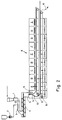
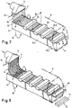
- the raw material is as a dry component via a dosage 1 and which as a liquid component via a liquid metering 2, a kneading device 3 and a press screw 4 and one Press head 5 supplied, of which dough strands 6 or donrdashery 6K formed by a die 7 and directly through a dryer 8 are passed.
- a conveyor system 9 guides the dough strands continuously in the dryer by a predetermined number of drying sections 8.1, 8.2 etc.
- FIG. 11 Air flow, to ensure the climate control and climate control on what's in this figure with a Fan wheel 10, and symbolically with a heating element 11 is indicated.
- the conveyor system 9 can be a perforated endless belt (not shown) or a later described by means of FIG. 10 Be a vibrator. In both cases it is advantageous an air flow shown with FIGS. 10 and 11 is provided, which is essentially vertical through the endless belt resp. flows through the vibratory conveyor.
- a stabilizer 12 Connected to the dryer 8 is a stabilizer 12 arranged.
- the stabilizer 12 is designed as a microwave stabilizer, so between dryer 8 and stabilizer 12th and between stabilizer 12 and a length cutting device 13, a lock 14 is provided, which as Microwave lock is formed.
- a lock 14 is provided, which as Microwave lock is formed.
- the arrow marked with it 15 is a cutting device described later on the Press mold 7 designated for short or long pasta.
- a cutting device can on the one hand at the beginning the defective extruded product is trimmed, or at the end a batch production the dough strands to a uniform End, or it can cut pasta of any length will.
- the arrow 16 indicates that with the same line, donrdashery and long goods can be produced, the dry goods with the Cross cutting device 15 are cut and according to Arrow 16 carried out in front of the length cutting device 13 will.
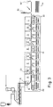
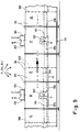
- FIG. 2 can be designed analogously to FIG. 1, but represents is a two-day version, with an upper one Conveyor system 9 and a lower conveyor system 9.1 which each the sub-strands 6 respectively. 6.1 through the dryer be performed.
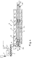
- Fig. 3 shows a very compact design of a complete System with the dough preparation and the drying of the Dough strands.
- the dryer in Fig. 3 is in one larger number of individual climate zones A, B, C, D etc. divided. There is one in each of climate zones B, D, F Microwave heating stage 23 is provided.
- a Goods collection means e.g. in the form of a conveyor belt 20, a Goods discharge means 22, and a straightening belt 21 in the middle Area arranged.
- the goods discharge means which can also be a conveyor belt can pull the dough strands lightly.
- the goods discharge means which can also be a conveyor belt can pull the dough strands lightly.
- a large number of Dough strands, carpet-like over a width of 1 to 2.5m is guided through the system, with sufficient air flow also several strands of dough on the same conveyor system can lie on top of each other.
- the drying air is, as described later, in the area a fluidized bed in recirculation mode and results in a high speed, respectively. by a corresponding one Buoyancy for the pasta contained therein that all strands of dough like a fluidized bed (also called a fluid bed) the different drying zones are worn.
- a fluidized bed drying is also in the CH patent No. 615,269 (also US Pat. No. 4,126,945) shown and described.
- the vibrotransporter described later advantageously has Longitudinal guides also called longitudinal pods, which gives the dough strands or donrdashery a longitudinal guide give.
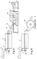
- FIG. 4 can be designed analogously to FIG. 1 be, however, analogous to the line of FIG. 2, a two-day Execution, with a corresponding upper one Conveyor system 9 and a lower conveyor system 9.1 which each the dough strands 6 respectively. 6.1 through the dryer be performed.
- 1, 2 and 4 are the previously mentioned conveyor belts shown which - as mentioned earlier - perforated are to enable the previously mentioned air flow.
- the vibratory conveyor described in its place there is also a possibility that later use the vibratory conveyor described in its place.
- the dryer of Figure 4 is like the dryer of Figure 2 in a larger number of individual climate zones A, B, C, D etc. divided up.
- each a microwave heating stage 23 can be provided.
- Such microwave heating levels are from case to case, according to specialist knowledge of the appropriate specialist.
- the donrdashery 30 fall after them from the cross cutting device 15 directly on the mold 7 were cut directly onto a later described Vortex dryer 31, which is approximately the same width dimension B has, as the long form 7.
- the vortex dryer 31 has the longitudinal pods 32 described earlier (also longitudinal guides called), which the suitcaserdashery 30 a longitudinal guide so that the goods do not concentrate on one side.
- the vortex dryer 31 has an optional heating stage 33 on, for increasing the product temperature.
- Such Heating stage can be an infrared stage, for example.
- the dryer 8 has the typical outer shape as shown in a PCT application with the number CH92 / 00060 (filing date: 01.04.92) is shown and described by the applicant, why in this application this system is not in full detail is described, but to the aforementioned PCT application is referenced.
- the reference numeral 35 is a stabilization level for the indicated dried goods. While stabilizing the pasta one understands a new one after the drying process Moistening the outer layer of the pasta cross-section, to avoid a late break.
- the donrdashery has moisture of less than 13%, and can then be stacked or be packed directly.
- Fig. 8 is in analogy to Fig. 7, in compliance with the Invention idea, a long goods line shown.
- the Dough strands are here at the beginning and end of a functional batch a uniform length by means of the cross cutting device 15 cut.
- the packaging length is however only at the outlet of the dryer 8 as here Guillotine shown cutting device 40 manufactured and the packaging lengths in transfer form 41 of the stacking in Containers or packaging supplied.
- FIG. 5 shows the solution of FIG. 8 with a subsequent one Container stacker 50, which via a transfer device 51 the cut goods as packaging lengths handed over in an orderly manner and packed as required.
- Only partially dried dry goods can also be combined in one Drum dryer arranged parallel to the container stacker 50 60 ready to be dried.
- the temperature of the goods is stepped down to less than 60 ° C be lowered, and the stabilization of the pasta over Microwaves are done.
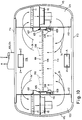
- Fig. 9 shows an enlarged section of the with 7 and 8 shown vortex dryer 31 and. 31.1 and 31.2, in which vibro-shaking channel, as related later 10, are resiliently mounted, so that by means of on vibrating elements 101 vibrating elements 102 den Vibra passedelrinnen 101 a movement in the direction of arrow S. is given so that the product in the direction V in the Vibro vibratory channels are promoted.
- each shaker has an upward incline accordingly the angle ⁇ to the horizontal H.
- the angle ⁇ becomes empirically determined, but fundamentally shows only a few Straight up.
- the separation points are transverse partition walls 100, which are indeed the Pass product from one shaker to the other, in terms of ventilation, however, essentially zones C, D and E, resp. Separate F from each other so that in each zone with the help of a circulating air system assigned to each zone according to FIG. 11 created its own climate and air circulation can be.
- the vibrating elements 102 are on a channel frame 105 provided which has a perforated channel bottom 106 records.
- the channel frame 105 is by means of Compression springs 110 are resiliently supported on a support element 109, to allow the aforementioned stroke in the S direction.
- the channel frame is on the one hand by means of a flexible seal 107 with a longitudinal partition 112 of Vortex dryer and on the other hand by means of a flexible Seal 108 with the aforementioned support member 109 connected, which in turn on the longitudinal partition 112 is attached.
- a perforated one Collecting tray 111 attached to the support members 109.
- the vortex dryer in the side chambers 123 one heating element 11 each for heating the circulating air and one Recirculation fan 10 on.
- the side chambers are covered on the outside with side walls 115, the side walls 115 each on a bottom part 113 and close to a ceiling part 114.
- the supply air is schematic with the arrows Z and the exhaust air shown with arrows A, this supply air resp. Exhaust air through one divided into parts 103 and 104 Channel off or is fed.
- FIGS. 9 and 10 are included provided the same reference numerals.
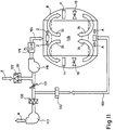
- Fig. 11 shows schematically that labeled "TURBOTERMATIK” Air circulation system per vortex dryer unit C, respectively. D, resp. E, resp. F etc., in which the same elements the same Have reference numerals as in FIGS. 9 and 10.
- an exhaust fan 117 one by a controller 132 and an air damper 121 draws regulated amount of exhaust air out of exhaust duct 103, while a supply air fan 118 is controlled by a controller 131 regulated supply air via a humidifier 119 into the 34 blows the designated air circulation system.
- the supply air Z can by means of a heating element 130 and Exhaust air can be heated by means of a heating element 130.
- the Heating the exhaust air serves to reduce the relative air humidity.
- the air can also be used to intensify the drying process a strong vibration is transmitted.
- Such vibrations can be generated using pulsating air.
- An example to generate such vibrations is known from DE-16 60 745 C2 (equivalent to US 41 26 945) of the applicant known.
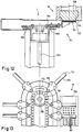
- FIGS. 12 and 13 also show the aforementioned long form 15 an attached shape cutting device 151.
- the form cutting device 151 has cutting knives 152, which are arranged on an endless chain 154.
- the cutting knives 152 have a cutting surface 153, which when moving the endless chain 154 in the moving direction 156 each through the dough bores 157 of the shape 158 cuts in given lengths according to speed.
- the endless chain 154 is driven by a drive (not shown) driven by a drive shaft 155.
- the knives 152 are arranged on a support part 159 which is connected on the one hand to the endless chain 154 and on the other hand rest on guide surfaces 160.
- the knives are arranged such that the cutting surfaces 153 on the lower mold surface 161 Cut pasta.
- the shaft 155 is either with a stepper motor (not shown) or / and with a gear variator (not shown) connected to the speed of the knife to vary on the one hand, and / or the aforementioned perform gradual movement.
- the device according to the invention is that the pasta immediately after cutting without further Surveys entered in the air-conditioned conveyor system can be.
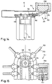
- FIG. 14 shows a form cutting device 251 with a Long form 15.1 with the difference compared to the cutting device 151 of FIG. 13 by the molding surface 261 and the Cutting surface 253 are not straight as in FIG. 12, but as seen in Fig. 14, a sawtooth shape exhibit.
- FIG. 16 differs from FIG. 12 in this respect than the long form 15.2 is no longer part of the form cutting device 351 is arranged, but detached therefrom is. Furthermore, the form cutting device 351 also has a "bevel cut", but not here as in Fig. 14 as a sawtooth, but as a linear bevel cut.
- the oblique shape surface is 361 and the oblique Cutting edge marked with 353.
- Such an intermediate form can also in connection with the Shape cutter 251 can be used by the sawtooth shape not directly on the form 258, but on an intermediate form (not shown) possible and even, as explained later, is desired.
- the endless chain 154 is driven by means of a motor 168 Motor shaft 355 driven.
- the guiding principle is that the Number of knives based on cutting speed and speed depend on the strand of dough.
- FIG 17 shows the intermediate form 162 on the form 158.
- the Approach situation of the form cutting device 351 corresponds, while Fig. 16 shows the mode of operation.
- This form of operation offers the possibility of being at a distance Depending on the size of this distance, a cooling or ventilation zone can be interposed.
- rollers 164 are rotatable in a stationary carrier 165 which also has a cylinder-piston unit 166 carries, which is connected on the piston side to an arm 167, which in turn is from the left, with a view of Fig. 16 seen, guide 163 is fixed, whereby the guides 163 and with them the whole form cutting device 351 on and as seen in FIG. 16, is movable to the Intermediate form 162 in contact with form 158 in the starting position and bring it back to the operating situation.
- the intermediate form 162 as can be seen from FIGS. 16 and 17, Part of the cutting device 351.
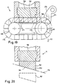
- FIG. 18 shows a long form 15.3 with a form 458, which differs in this respect from the shape 158 of FIG. 12, than the cutting edge or the cutting surface has concave curvature, so that a cutting rotor 169 with attached cutting knife 170 for cutting the Pasta on form 453 is usable.
- the Cutting knife 170 as shown in solid lines, radial or, as shown with dash-dotted lines, be tilted.
- the cutting blades 170 fall on the cutting surface 453 cut pasta on rotor surface 197 and due to the rotation according to arrow direction 198 finally in Direction of arrow 172 in dryer 8 described earlier.
- the rotor is rotatably supported by means of a shaft 171 and driven.
- FIG. 19 shows an alternative to the cutting device 18, as here not a cutting rotor, but a cutting belt 176 is provided which is equipped with knives 177 is provided to the pasta on the cutting surface 153 of the Cut shape 158.
- the knives can be pulled out Lines perpendicular to the band or according to dashed lines Lines must be arranged at an angle.
- the cutting belt 176 is guided on deflection rollers 180 and 181 and can be driven with one of the two shafts.
- a fan 273 with guide vanes can be used 274 are provided to the surface and therefore to ventilate the pasta with warm or cool air and how with the pulley shown with dashed lines 181 the length of the cutting belt 176 can be chosen arbitrarily so that the ventilation by means of a fan 273 or chosen without fan accordingly can be.
- heating elements Also shown with 179 heating elements and show that the belt 176 is heated.
- FIGS. 16 and 17 162 are intermediate forms analogous to FIGS. 16 and 17 162 provided that the cutting tape 176 obliquely, as shown by the dash-dotted line, is arranged to a bevel cut mentioned earlier produce.
- the molding surface 361 and the cutting surface 353 are accordingly also shown obliquely.
- the intermediate form 162 shown with dashed lines is to illustrate that analogous to the description of FIGS and 17 the intermediate mold 162 a starting position and an operating position may have.
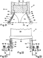
- 21 and 22 show a long form 15, on which a Cutting knife 185 cuts across the longitudinal direction of the long form, in contrast to the knives 152 of FIGS. 12 and 13, which move in the longitudinal direction of the mold for cutting.
- the knife 185 is on a telescopic arm 184 attached, which by means of a pivot bearing 187 on a Swivel pin 192 is rotatably mounted, which in turn is part a slide guide 193 which is along a slide rail is slidable, which is provided such that the pivot bearing 187 movable back and forth along a movement path 200 is.
- the aforementioned telescopic arm 184 is therefore telescopic, so the knife 185 is marked with the angle ⁇ or ⁇ .1 Can assume an inclined position.
- the pivot bearing 187 To the movement of the pivot bearing 187 along the path of movement 200 to perform, the pivot bearing 187 with a Piston rod of a piston-cylinder unit connected (only in 22 and 22.1). The latter piston-cylinder unit is not shown further and can be completely normal reversible unit.
- the telescopic arm must be flexible enough that the Snap-in cam 188 for changing position from the snap-in groove 189 can switch into the snap-in groove 190 and vice versa.
- the knife 185 can, as shown in Fig. 22, with the Advantage that the stops 182 and 183 may not below, but on the end faces of the long form can.
Landscapes
- Engineering & Computer Science (AREA)
- Mechanical Engineering (AREA)
- General Engineering & Computer Science (AREA)
- Life Sciences & Earth Sciences (AREA)
- Food Science & Technology (AREA)
- Noodles (AREA)
- Manufacturing And Processing Devices For Dough (AREA)
- Drying Of Solid Materials (AREA)
Abstract
Claims (25)
- Procédé destiné à fabriquer des pâtes alimentaires courtes (6) et longues (30), par moulage à la presse par l'intermédiaire d'une filière ou moule (7), et ensuite à sécher celles-ci dans un séchoir tunnel en continu (8) à lit fluidisé (4), le moulage à la presse s'effectuant sur toute la largeur (B) du séchoir tunnel en continu (8), et les pâtes alimentaires (6, 30) étant envoyées directement dans la couche fluidisée, caractérisé en ce que les pâtes alimentaires (6, 30) sont amenées directement à travers une zone de pré-séchage (8.0) et ensuite dans un plan sensiblement horizontal en y étant maintenues pour le séchage dans la zone de séchage principal (8.1ff), et en ce que les pâtes courtes (6) sont coupées directement à la suite du moulage à la presse (7), à l'intérieur de la zone de pré-séchage (8.0), et les pâtes longues (30) sont coupées après séchage complet ou partiel.
- Procédé selon la revendication 1, caractérisé en ce que le pressage des pâtes (6, 30) s'effectue par l'intermédiaire d'une filière ou moule long ou des moules de surface circulaire.
- Procédé selon les revendications 1 ou 2, caractérisé en ce que la température des pâtes (6, 30) est élevée de la température de pressage, jusqu'à plus de 70°C, de préférence à plus de 80°C.
- Procédé selon l'une au moins des revendications 1 à 3, caractérisé en ce que les pâtes, après un pré-séchage, sous forme de tige chaude à au moins 70°C, sont séchées soit en longueurs de séchage, soit coupées en longueurs de pâtes finies, et sont séchées à l'état chaud, selon un procédé de séchage de masse connu en soi, ou sont amenées au séchage principal.
- Procédé selon la revendication 4, caractérisé en ce que les pâtes ne sont séchées que jusqu'à présenter une résistance de forme suffisante, à moins de 28%, de préférence moins de 25% d'humidité, et sont coupées à l'état humide.
- Procédé selon la revendication 5, caractérisé en ce qu'on achève ensuite le séchage des pâtes coupées (6, 30), par exemple par portions, à une humidité du produit inférieure à 13%.
- Procédé selon la revendication 1, caractérisé en ce que le séchage s'effectue dans un nombre plus important d'étages de séchage (8.0, 8.1, 8.2, 8.3, 8.4, 8.5, 8.6, A, B, C, D, E, F, G, H, I), chaque étage présentant une propre commande de climatisation ainsi qu'un propre système de circulation d'air, et en ce que le pré-séchage des pâtes alimentaires s'effectue de préférence à une température des pâtes de 70°C jusqu'à 80°C et plus, et le séchage principal à une température des pâtes de 80°C à 150°C, de préférence de 90°C à 125°C.
- Procédé selon la revendication 7, caractérisé en ce que les pâtes alimentaires (6, 30) sont déplacées horizontalement et l'air de séchage est mis en circulation verticalement, transversalement aux pâtes alimentaires (6, 30), l'air étant de préférence pulsé et mis en oscillation pour augmenter l'effet de séchage, et en ce que la vitesse de l'air peut être commandée, de sorte qu'il s'établit une fluidisation des tiges de pâtes, les tiges de pâtes étant de préférence guidées par-dessus un moyen de transport en continu, tel que par exemple au-dessus d'une bande transporteuse sans fin (20, 21, 22) perméable à l'air, ou bien une unité de transport par vibrations (101) perméable à l'air.
- Ligne de fabrication de pâtes alimentaires pour la fabrication de pâtes alimentaires longues (6) ou courtes (30), et destinée à la mise en oeuvre du procédé selon l'une au moins des revendications précédentes, la ligne comprenant un séchoir (8.0ff) se présentant sous la forme d'un séchoir tunnel, ainsi qu'une presse de moulage (7) s'étendant sur toute la largeur du séchoir (8.0ff), caractérisée en ce que directement à la suite de la filière ou du moule de presse (7), est disposé le séchoir présentant une zone de pré-séchage (8.0) fermée à l'encontre de l'air extérieur, et une zone de séchage principale (8.1ff), en ce que le séchoir tunnel présente un système de transport de passage continu pour les pâtes alimentaires, s'étendant sensiblement dans un plan horizontal, et en ce qu'un dispositif de coupe (15) prévu pour les pâtes alimentaires courtes (6) est disposé à l'intérieur de la zone de pré-séchage (8.0), et un dispositif de coupe (13) prévu pour les pâtes alimentaires longues (30) est disposé dans la zone du séchoir (8.1ff) ou à la fin de la ligne.
- Ligne de fabrication de pâtes alimentaires selon la revendication 9, caractérisée en ce que le moule (7) se présente soit sous la forme d'un moule long s'étendant sur la largeur (B) du séchoir (8), soit sous la forme de moules individuels s'étendant sur la largeur (B) du séchoir.
- Ligne de fabrication de pâtes alimentaires selon la revendication 9 ou 10, caractérisée en ce qu'un dispositif de coupe (15) est associé au moule de presse (7) et comporte des couteaux, qui, pour la coupe des pâtes alimentaires, se déplacent dans une direction s'étendant sur la largeur (B) du séchoir.
- Ligne de fabrication de pâtes alimentaires selon la revendication 9 ou 10, caractérisée en ce qu'un dispositif de coupe (15) est associé au moule de presse (7) et comporte des couteaux (152) qui, pour la coupe des pâtes alimentaires, se déplacent dans une direction s'étendant dans la direction longitudinale du séchoir (8).
- Ligne de fabrication de pâtes alimentaires selon la revendication 9, caractérisée en ce que sont prévus des moules individuels, un dispositif de coupe étant prévu par alésage de moule de pâtes (157) disposés de manière circulaire, le couteau (152) des dispositifs de coupe se déplaçant de manière circulaire pour la coupe des pâtes alimentaires.
- Ligne de fabrication de pâtes alimentaires selon la revendication 11 ou 12, caractérisée en ce que les couteaux (152) ne sont déplacés que dans la direction de coupe (156), et sont éloignés du moule après la dernière coupe.
- Ligne de fabrication de pâtes alimentaires selon la revendication 14, caractérisée en ce que les couteaux (152) sont déplacés selon un mouvement sans fin.
- Ligne de fabrication de pâtes alimentaires selon la revendication 15, caractérisée en ce que les couteaux (152) sont disposés sur une chaíne sans fin (154).
- Ligne de fabrication de pâtes alimentaires selon la revendication 15, caractérisée en ce que les couteaux (152) sont disposés sur une bande sans fin (176).
- Ligne de fabrication de pâtes alimentaires selon la revendication 15, caractérisée en ce que les couteaux (152) sont disposés sur un tambour (155).
- Ligne de fabrication de pâtes alimentaires selon la revendication 17 ou 18, caractérisée en ce que la bande sans fin (176) ou le tambour peuvent être chauffés.
- Ligne de fabrication de pâtes alimentaires selon la revendication 17 ou 18, caractérisée en ce qu'il est prévu un dispositif pour ventiler la surface de la bande sans fin (176) ou du tambour.
- Ligne de fabrication de pâtes alimentaires selon la revendication 12, caractérisée en ce que les couteaux (185) pour la coupe des pâtes alimentaires, peuvent être déplacés selon un mouvement alternatif de va-et-vient sur le moule.
- Ligne de fabrication de pâtes alimentaires selon la revendication 21, caractérisée en ce que les couteaux (185) sont déplacés dans un guidage linéaire.
- Ligne de fabrication de pâtes alimentaires selon la revendication 21, caractérisée en ce que les couteaux (185) présentent chacun une inclinaison (α) par rapport à la surface de coupe du moule de presse.
- Ligne de fabrication de pâtes alimentaires selon la revendication 9, caractérisée en ce qu'il est prévu un second dispositif de coupe qui durant la coupe des pâtes alimentaires peut être déplacé à la vitesses des pâtes alimentaires.
- Ligne de fabrication de pâtes alimentaires selon la revendication 9, caractérisée en ce qu'il est prévu un guide de pâtes entre la presse et le séchoir, et en ce que le dispositif de coupe coupe les pâtes alimentaires au niveau de ce guide de pâtes.
Applications Claiming Priority (3)
| Application Number | Priority Date | Filing Date | Title |
|---|---|---|---|
| CH2454/91 | 1991-08-21 | ||
| CH245491 | 1991-08-21 | ||
| PCT/CH1992/000166 WO1993003620A1 (fr) | 1991-08-21 | 1992-08-20 | Procede et dispositif de moulage par compression et de sechage de pates alimentaires |
Publications (2)
| Publication Number | Publication Date |
|---|---|
| EP0553323A1 EP0553323A1 (fr) | 1993-08-04 |
| EP0553323B1 true EP0553323B1 (fr) | 1998-01-07 |
Family
ID=4234196
Family Applications (1)
| Application Number | Title | Priority Date | Filing Date |
|---|---|---|---|
| EP92916932A Expired - Lifetime EP0553323B1 (fr) | 1991-08-21 | 1992-08-20 | Procede et dispositif de moulage par compression et de sechage de pates alimentaires |
Country Status (9)
| Country | Link |
|---|---|
| US (1) | US5364651A (fr) |
| EP (1) | EP0553323B1 (fr) |
| JP (1) | JP3183347B2 (fr) |
| BR (1) | BR9205324A (fr) |
| DE (1) | DE59209112D1 (fr) |
| ES (1) | ES2112325T3 (fr) |
| RU (1) | RU2091042C1 (fr) |
| UA (1) | UA26217C2 (fr) |
| WO (1) | WO1993003620A1 (fr) |
Families Citing this family (12)
| Publication number | Priority date | Publication date | Assignee | Title |
|---|---|---|---|---|
| FR2720900A1 (fr) * | 1994-06-14 | 1995-12-15 | Philippe Gesnouin | Procédé et dispositif pour la préparation de produit du type panifié et produit ainsi obtenu. |
| IT239788Y1 (it) * | 1996-07-26 | 2001-03-13 | Imperia Trading S R L | Macchina ad uso domestico per la fabbricazione, il taglio e laconformazione di paste alimentari . |
| KR20020082514A (ko) * | 2001-04-24 | 2002-10-31 | 주식회사 씨앤케이 | 광 상관기 |
| WO2004043152A1 (fr) * | 2002-11-14 | 2004-05-27 | Yavorsky Vladimir Vladimirovic | Procede d'egalisation de la longueur de produits en fonction d'un moule d'une presse a pates et moule permettant d'appliquer ce procede |
| EP2166864B8 (fr) * | 2007-07-02 | 2017-12-13 | Institut de Recerca i Tecnologia Agroalimentàries | Procédé pour sécher des produits alimentaires et installation pour mettre en uvre ledit procédé |
| KR101156481B1 (ko) * | 2009-12-10 | 2012-06-18 | 신한엔지니어링 주식회사 | 슬러지 건조용 컨베이어 |
| DE102010032141A1 (de) * | 2010-07-24 | 2012-01-26 | Fraunhofer-Gesellschaft zur Förderung der angewandten Forschung e.V. | Apparat zur Trocknung mittels eines heißen Gases |
| EP2526777A1 (fr) * | 2011-05-24 | 2012-11-28 | Feltracon B.V. | Device and method for drying vegetable and lettuce leaves |
| RU167724U1 (ru) * | 2016-06-15 | 2017-01-10 | Федеральное государственное казенное военное образовательное учреждение высшего образования "Военная академия материально-технического обеспечения имени генерала армии А.В. Хрулёва" Министерства обороны Российской Федерации | Устройство для сушки макаронных изделий ускоренным способом |
| IT201900020294A1 (it) * | 2019-11-04 | 2021-05-04 | Wealth & Res Trading Ltd | Impianto per produrre pasta secca alimentare |
| CN112857106A (zh) * | 2019-12-17 | 2021-05-28 | 肖东初 | 一种流化床冷却机及其操作方法 |
| CN114935253B (zh) * | 2022-06-16 | 2024-04-02 | 杭州港华纺织有限公司 | 一种耐久性中空纤维加工设备及制备方法 |
Family Cites Families (12)
| Publication number | Priority date | Publication date | Assignee | Title |
|---|---|---|---|---|
| CH347483A (de) * | 1956-04-04 | 1960-06-30 | Buehler Ag Geb | Verfahren zum Trocknen von Teigwaren |
| CA1083808A (fr) * | 1975-07-31 | 1980-08-19 | Josef Manser | Methode et appareil de traitement et notamment de sechage de produits granulaires en vrac |
| CH615269A5 (en) * | 1976-07-26 | 1980-01-15 | Buehler Ag Geb | Method and device for treating bulk material, in particular for expelling water from and drying farinaceous products |
| US4126706A (en) * | 1976-08-30 | 1978-11-21 | Frito-Lay, Inc. | Process for forming dough ribbon |
| GB2043424B (en) * | 1979-02-19 | 1983-04-13 | Sanyo Shokuhin Kk | Instant noodle |
| GB2043860B (en) * | 1979-03-15 | 1983-04-20 | Remonato G Remonato F | Multistage continuous drying apparatus especially for tanned hides |
| DE66661T1 (de) * | 1981-05-25 | 1984-07-19 | M.E.G. Materiels Equipements Graphiques S.A., Morangis | Vorrichtung zum trocknen von bahnen durch heissluft bei gleichzeitiger unterstuetzung der bahn, vorzugsweise von papierbahnen aus druckmaschinen. |
| DE3121348A1 (de) * | 1981-05-29 | 1982-12-16 | Babcock-BSH AG vormals Büttner-Schilde-Haas AG, 4150 Krefeld | Durchlauftrockner fuer messerfurniere |
| US4469711A (en) * | 1981-10-01 | 1984-09-04 | Rutgers Research & Educational Foundation | Process for making quick-cooking pasta |
| EP0086246A1 (fr) * | 1982-02-16 | 1983-08-24 | Kanebo Foods, Ltd. | Procédé pour la fabrication de nouilles séchées non-frites à cuisson instantanée et appareil pour la mise en oeuvre |
| FR2523707A1 (fr) * | 1982-03-18 | 1983-09-23 | Bassano Co | Dispositif de variation periodique du trajet de l'air pour sechoir a cellules successives pour pates alimentaires et analogues |
| DE3400300C2 (de) * | 1983-06-24 | 1986-01-23 | Gebrüder Bühler AG, Uzwil | Verfahren zur Herstellung von langen Teigwaren und Vorrichtung zur Durchführung eines solchen Verfahrens |
-
1992
- 1992-08-20 EP EP92916932A patent/EP0553323B1/fr not_active Expired - Lifetime
- 1992-08-20 ES ES92916932T patent/ES2112325T3/es not_active Expired - Lifetime
- 1992-08-20 WO PCT/CH1992/000166 patent/WO1993003620A1/fr active IP Right Grant
- 1992-08-20 JP JP50400193A patent/JP3183347B2/ja not_active Expired - Fee Related
- 1992-08-20 RU RU9293005062A patent/RU2091042C1/ru not_active IP Right Cessation
- 1992-08-20 UA UA93004144A patent/UA26217C2/uk unknown
- 1992-08-20 US US08/030,499 patent/US5364651A/en not_active Expired - Fee Related
- 1992-08-20 DE DE59209112T patent/DE59209112D1/de not_active Expired - Fee Related
- 1992-08-20 BR BR9205324A patent/BR9205324A/pt not_active IP Right Cessation
Also Published As
| Publication number | Publication date |
|---|---|
| RU2091042C1 (ru) | 1997-09-27 |
| US5364651A (en) | 1994-11-15 |
| WO1993003620A1 (fr) | 1993-03-04 |
| JPH06502083A (ja) | 1994-03-10 |
| UA26217C2 (uk) | 1999-07-19 |
| DE59209112D1 (de) | 1998-02-12 |
| JP3183347B2 (ja) | 2001-07-09 |
| BR9205324A (pt) | 1994-05-31 |
| EP0553323A1 (fr) | 1993-08-04 |
| ES2112325T3 (es) | 1998-04-01 |
Similar Documents
| Publication | Publication Date | Title |
|---|---|---|
| EP0551464B1 (fr) | Procede et dispositif de compression et de sechage de pates alimentaires allongees | |
| DE2634267A1 (de) | Verfahren und vorrichtung zum behandeln von schuettgut, insbesondere zur wasseraustreibung und trocknung von teigwaren | |
| EP0553323B1 (fr) | Procede et dispositif de moulage par compression et de sechage de pates alimentaires | |
| DE60215171T2 (de) | Vorrichtung zum massieren von produkten | |
| DE3030604C2 (fr) | ||
| DE3217643A1 (de) | Misch- und ablegevorrichtung fuer suess- und backwarenmassen | |
| DE2540124C2 (de) | Einrichtung zum Belüften und Mischen eines fließfähigen Feststoffmaterials | |
| DE3113575A1 (de) | Verfahren zur herstellung einer zigarettenfiltereinheit und einrichtung zur durchfuehrung des verfahrens | |
| DE1904006A1 (de) | Verfahren und Vorrichtung zum Wellen eines Blattes oder einer Bahn aus biegsamem Material | |
| DE2905284A1 (de) | Verfahren und vorrichtung zur herstellung von backwaren, insbesondere brot | |
| DE102006061340B3 (de) | Verfahren und Einrichtung zum Herstellen von Holzpellets sowie Einrichtung zum Trocknen | |
| DE2735395A1 (de) | Verfahren und geraet zum trocknen von feingussformen | |
| DE3328589C2 (fr) | ||
| DE1994335U (de) | Vorrichtung zum verarbeiten von insbesondere zur bildung des tabakfuellers an strangzigarettenmaschinen bestimmtem tabak. | |
| DE2638687C2 (de) | Verfahren und Vorrichtung zum Herstellen einer gleichmäßigen Schicht von losen Fasern oder Partikeln auf einer bewegten porösen Trägerbahn | |
| DE2731555C2 (de) | Verfahren und Vorrichtung zum automatischen Trocknen von Produkten | |
| CH615269A5 (en) | Method and device for treating bulk material, in particular for expelling water from and drying farinaceous products | |
| DE2403776C2 (de) | Vorrichtung zur Herstellung eines Schaumkunststoffstranges | |
| EP0583447A1 (fr) | Procede et dispositif de fabrication de longs rubans de pate, par exemple de lasagnes | |
| DD211938A5 (de) | Verfahren und vorrichtung zum trocknen keramischer formlinge | |
| DE2555929C3 (de) | Vorrichtung zum Herstellen dünner Teigschichten | |
| DE3327479C1 (de) | Vorrichtung zur Herstellung von Granulat | |
| DE306748C (fr) | ||
| DE2551333A1 (de) | Vorrichtung zur herstellung eines strangfoermigen koerpers aus schaumkunststoff | |
| DE1782155C3 (de) | Verfahren und Vorrichtung zum Herstellen von Cheddar- oder Chesterkäse |
Legal Events
| Date | Code | Title | Description |
|---|---|---|---|
| PUAI | Public reference made under article 153(3) epc to a published international application that has entered the european phase |
Free format text: ORIGINAL CODE: 0009012 |
|
| 17P | Request for examination filed |
Effective date: 19930323 |
|
| AK | Designated contracting states |
Kind code of ref document: A1 Designated state(s): CH DE ES FR GB IT LI NL SE |
|
| 17Q | First examination report despatched |
Effective date: 19950217 |
|
| GRAG | Despatch of communication of intention to grant |
Free format text: ORIGINAL CODE: EPIDOS AGRA |
|
| GRAG | Despatch of communication of intention to grant |
Free format text: ORIGINAL CODE: EPIDOS AGRA |
|
| GRAH | Despatch of communication of intention to grant a patent |
Free format text: ORIGINAL CODE: EPIDOS IGRA |
|
| GRAH | Despatch of communication of intention to grant a patent |
Free format text: ORIGINAL CODE: EPIDOS IGRA |
|
| GRAA | (expected) grant |
Free format text: ORIGINAL CODE: 0009210 |
|
| AK | Designated contracting states |
Kind code of ref document: B1 Designated state(s): CH DE ES FR GB IT LI NL SE |
|
| PG25 | Lapsed in a contracting state [announced via postgrant information from national office to epo] |
Ref country code: NL Free format text: LAPSE BECAUSE OF FAILURE TO SUBMIT A TRANSLATION OF THE DESCRIPTION OR TO PAY THE FEE WITHIN THE PRESCRIBED TIME-LIMIT Effective date: 19980107 |
|
| REG | Reference to a national code |
Ref country code: CH Ref legal event code: EP |
|
| REF | Corresponds to: |
Ref document number: 59209112 Country of ref document: DE Date of ref document: 19980212 |
|
| ET | Fr: translation filed | ||
| REG | Reference to a national code |
Ref country code: ES Ref legal event code: FG2A Ref document number: 2112325 Country of ref document: ES Kind code of ref document: T3 |
|
| PG25 | Lapsed in a contracting state [announced via postgrant information from national office to epo] |
Ref country code: SE Free format text: LAPSE BECAUSE OF FAILURE TO SUBMIT A TRANSLATION OF THE DESCRIPTION OR TO PAY THE FEE WITHIN THE PRESCRIBED TIME-LIMIT Effective date: 19980407 |
|
| GBT | Gb: translation of ep patent filed (gb section 77(6)(a)/1977) |
Effective date: 19980330 |
|
| NLV1 | Nl: lapsed or annulled due to failure to fulfill the requirements of art. 29p and 29m of the patents act | ||
| PLBE | No opposition filed within time limit |
Free format text: ORIGINAL CODE: 0009261 |
|
| STAA | Information on the status of an ep patent application or granted ep patent |
Free format text: STATUS: NO OPPOSITION FILED WITHIN TIME LIMIT |
|
| 26N | No opposition filed | ||
| REG | Reference to a national code |
Ref country code: GB Ref legal event code: IF02 |
|
| PGFP | Annual fee paid to national office [announced via postgrant information from national office to epo] |
Ref country code: CH Payment date: 20030708 Year of fee payment: 12 |
|
| PGFP | Annual fee paid to national office [announced via postgrant information from national office to epo] |
Ref country code: GB Payment date: 20030728 Year of fee payment: 12 |
|
| PGFP | Annual fee paid to national office [announced via postgrant information from national office to epo] |
Ref country code: DE Payment date: 20030805 Year of fee payment: 12 |
|
| PGFP | Annual fee paid to national office [announced via postgrant information from national office to epo] |
Ref country code: ES Payment date: 20030807 Year of fee payment: 12 |
|
| PGFP | Annual fee paid to national office [announced via postgrant information from national office to epo] |
Ref country code: FR Payment date: 20030813 Year of fee payment: 12 |
|
| PG25 | Lapsed in a contracting state [announced via postgrant information from national office to epo] |
Ref country code: GB Free format text: LAPSE BECAUSE OF NON-PAYMENT OF DUE FEES Effective date: 20040820 |
|
| PG25 | Lapsed in a contracting state [announced via postgrant information from national office to epo] |
Ref country code: ES Free format text: LAPSE BECAUSE OF NON-PAYMENT OF DUE FEES Effective date: 20040821 |
|
| PG25 | Lapsed in a contracting state [announced via postgrant information from national office to epo] |
Ref country code: LI Free format text: LAPSE BECAUSE OF NON-PAYMENT OF DUE FEES Effective date: 20040831 Ref country code: CH Free format text: LAPSE BECAUSE OF NON-PAYMENT OF DUE FEES Effective date: 20040831 |
|
| PG25 | Lapsed in a contracting state [announced via postgrant information from national office to epo] |
Ref country code: DE Free format text: LAPSE BECAUSE OF NON-PAYMENT OF DUE FEES Effective date: 20050301 |
|
| GBPC | Gb: european patent ceased through non-payment of renewal fee |
Effective date: 20040820 |
|
| REG | Reference to a national code |
Ref country code: CH Ref legal event code: PL |
|
| PG25 | Lapsed in a contracting state [announced via postgrant information from national office to epo] |
Ref country code: FR Free format text: LAPSE BECAUSE OF NON-PAYMENT OF DUE FEES Effective date: 20050429 |
|
| REG | Reference to a national code |
Ref country code: FR Ref legal event code: ST |
|
| REG | Reference to a national code |
Ref country code: ES Ref legal event code: FD2A Effective date: 20040821 |
|
| PGFP | Annual fee paid to national office [announced via postgrant information from national office to epo] |
Ref country code: IT Payment date: 20090812 Year of fee payment: 18 |
|
| PG25 | Lapsed in a contracting state [announced via postgrant information from national office to epo] |
Ref country code: IT Free format text: LAPSE BECAUSE OF NON-PAYMENT OF DUE FEES Effective date: 20100820 |