EP0551601A1 - Dispositif et procédé pour l'alimentation spécialement de produits imprimés pliés vers un autre poste de travail - Google Patents
Dispositif et procédé pour l'alimentation spécialement de produits imprimés pliés vers un autre poste de travail Download PDFInfo
- Publication number
- EP0551601A1 EP0551601A1 EP92120375A EP92120375A EP0551601A1 EP 0551601 A1 EP0551601 A1 EP 0551601A1 EP 92120375 A EP92120375 A EP 92120375A EP 92120375 A EP92120375 A EP 92120375A EP 0551601 A1 EP0551601 A1 EP 0551601A1
- Authority
- EP
- European Patent Office
- Prior art keywords
- printed products
- conveying
- intermediate stack
- conveyor
- conveying device
- Prior art date
- Legal status (The legal status is an assumption and is not a legal conclusion. Google has not performed a legal analysis and makes no representation as to the accuracy of the status listed.)
- Granted
Links
Images


Classifications
-
- B—PERFORMING OPERATIONS; TRANSPORTING
- B41—PRINTING; LINING MACHINES; TYPEWRITERS; STAMPS
- B41F—PRINTING MACHINES OR PRESSES
- B41F13/00—Common details of rotary presses or machines
- B41F13/54—Auxiliary folding, cutting, collecting or depositing of sheets or webs
-
- B—PERFORMING OPERATIONS; TRANSPORTING
- B65—CONVEYING; PACKING; STORING; HANDLING THIN OR FILAMENTARY MATERIAL
- B65H—HANDLING THIN OR FILAMENTARY MATERIAL, e.g. SHEETS, WEBS, CABLES
- B65H29/00—Delivering or advancing articles from machines; Advancing articles to or into piles
- B65H29/66—Advancing articles in overlapping streams
- B65H29/669—Advancing articles in overlapping streams ending an overlapping stream
-
- B—PERFORMING OPERATIONS; TRANSPORTING
- B65—CONVEYING; PACKING; STORING; HANDLING THIN OR FILAMENTARY MATERIAL
- B65H—HANDLING THIN OR FILAMENTARY MATERIAL, e.g. SHEETS, WEBS, CABLES
- B65H29/00—Delivering or advancing articles from machines; Advancing articles to or into piles
- B65H29/003—Delivering or advancing articles from machines; Advancing articles to or into piles by grippers
-
- B—PERFORMING OPERATIONS; TRANSPORTING
- B65—CONVEYING; PACKING; STORING; HANDLING THIN OR FILAMENTARY MATERIAL
- B65H—HANDLING THIN OR FILAMENTARY MATERIAL, e.g. SHEETS, WEBS, CABLES
- B65H29/00—Delivering or advancing articles from machines; Advancing articles to or into piles
- B65H29/24—Delivering or advancing articles from machines; Advancing articles to or into piles by air blast or suction apparatus
-
- B—PERFORMING OPERATIONS; TRANSPORTING
- B65—CONVEYING; PACKING; STORING; HANDLING THIN OR FILAMENTARY MATERIAL
- B65H—HANDLING THIN OR FILAMENTARY MATERIAL, e.g. SHEETS, WEBS, CABLES
- B65H83/00—Combinations of piling and depiling operations, e.g. performed simultaneously, of interest apart from the single operation of piling or depiling as such
- B65H83/02—Combinations of piling and depiling operations, e.g. performed simultaneously, of interest apart from the single operation of piling or depiling as such performed on the same pile or stack
-
- B—PERFORMING OPERATIONS; TRANSPORTING
- B65—CONVEYING; PACKING; STORING; HANDLING THIN OR FILAMENTARY MATERIAL
- B65H—HANDLING THIN OR FILAMENTARY MATERIAL, e.g. SHEETS, WEBS, CABLES
- B65H2301/00—Handling processes for sheets or webs
- B65H2301/40—Type of handling process
- B65H2301/42—Piling, depiling, handling piles
- B65H2301/421—Forming a pile
- B65H2301/4212—Forming a pile of articles substantially horizontal
- B65H2301/42122—Forming a pile of articles substantially horizontal by introducing articles from under the pile
-
- B—PERFORMING OPERATIONS; TRANSPORTING
- B65—CONVEYING; PACKING; STORING; HANDLING THIN OR FILAMENTARY MATERIAL
- B65H—HANDLING THIN OR FILAMENTARY MATERIAL, e.g. SHEETS, WEBS, CABLES
- B65H2301/00—Handling processes for sheets or webs
- B65H2301/40—Type of handling process
- B65H2301/42—Piling, depiling, handling piles
- B65H2301/421—Forming a pile
- B65H2301/4213—Forming a pile of a limited number of articles, e.g. buffering, forming bundles
-
- B—PERFORMING OPERATIONS; TRANSPORTING
- B65—CONVEYING; PACKING; STORING; HANDLING THIN OR FILAMENTARY MATERIAL
- B65H—HANDLING THIN OR FILAMENTARY MATERIAL, e.g. SHEETS, WEBS, CABLES
- B65H2301/00—Handling processes for sheets or webs
- B65H2301/40—Type of handling process
- B65H2301/44—Moving, forwarding, guiding material
- B65H2301/447—Moving, forwarding, guiding material transferring material between transport devices
- B65H2301/4471—Grippers, e.g. moved in paths enclosing an area
- B65H2301/44712—Grippers, e.g. moved in paths enclosing an area carried by chains or bands
-
- B—PERFORMING OPERATIONS; TRANSPORTING
- B65—CONVEYING; PACKING; STORING; HANDLING THIN OR FILAMENTARY MATERIAL
- B65H—HANDLING THIN OR FILAMENTARY MATERIAL, e.g. SHEETS, WEBS, CABLES
- B65H2301/00—Handling processes for sheets or webs
- B65H2301/40—Type of handling process
- B65H2301/44—Moving, forwarding, guiding material
- B65H2301/447—Moving, forwarding, guiding material transferring material between transport devices
- B65H2301/4472—Suction grippers, e.g. moved in paths enclosing an area
-
- B—PERFORMING OPERATIONS; TRANSPORTING
- B65—CONVEYING; PACKING; STORING; HANDLING THIN OR FILAMENTARY MATERIAL
- B65H—HANDLING THIN OR FILAMENTARY MATERIAL, e.g. SHEETS, WEBS, CABLES
- B65H2301/00—Handling processes for sheets or webs
- B65H2301/40—Type of handling process
- B65H2301/44—Moving, forwarding, guiding material
- B65H2301/447—Moving, forwarding, guiding material transferring material between transport devices
- B65H2301/4473—Belts, endless moving elements on which the material is in surface contact
- B65H2301/44732—Belts, endless moving elements on which the material is in surface contact transporting articles in overlapping stream
-
- B—PERFORMING OPERATIONS; TRANSPORTING
- B65—CONVEYING; PACKING; STORING; HANDLING THIN OR FILAMENTARY MATERIAL
- B65H—HANDLING THIN OR FILAMENTARY MATERIAL, e.g. SHEETS, WEBS, CABLES
- B65H2301/00—Handling processes for sheets or webs
- B65H2301/40—Type of handling process
- B65H2301/44—Moving, forwarding, guiding material
- B65H2301/447—Moving, forwarding, guiding material transferring material between transport devices
- B65H2301/4474—Pair of cooperating moving elements as rollers, belts forming nip into which material is transported
-
- B—PERFORMING OPERATIONS; TRANSPORTING
- B65—CONVEYING; PACKING; STORING; HANDLING THIN OR FILAMENTARY MATERIAL
- B65H—HANDLING THIN OR FILAMENTARY MATERIAL, e.g. SHEETS, WEBS, CABLES
- B65H2405/00—Parts for holding the handled material
- B65H2405/50—Gripping means
- B65H2405/58—Means for achieving gripping/releasing operation
- B65H2405/583—Details of gripper orientation
- B65H2405/5832—Details of gripper orientation and varying its orientation after gripping
Definitions
- the present invention relates to a method and a device for feeding preferably folded printed products to a further processing point according to the preamble of claim 1 and claim 6.
- the supplied printed products in the transfer area are inserted directly into the passing open grippers of the conveyor by the feed conveyor.
- the conveying direction of the away conveyor runs in the transfer area of the printed products from bottom to top and transversely to the conveying direction of the supplied printed products.
- the present invention is based on the object of creating a method and a device of the type mentioned at the outset which allow the printed products to be fed to a further processing point in the desired sequence, regardless of the quality of the flake formation supplied.
- the supplied printed products are first inserted into an intermediate stack, from which they are removed from above by the suction arrangement and fed to the second conveyor, the supply of the printed products to the second conveyor is decoupled from the supply of the printed products by the first conveyor. This means that too large or too small distances between successive printed products and also missing printed products in the shingled stream supplied no longer influence the correct supply of printed products to the second conveying device. Such irregularities in the resulting scale formation are compensated for by the intermediate stack.
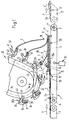
- FIGS. 1-3 A first embodiment of a device according to the invention will now be described with reference to FIGS. 1-3.
- This device has a first conveyor device 1, which delivers folded printed products 2 in a scale formation S.
- each printed product rests on the subsequent product 2.
- the trailing edge 2a of the printed products 2 lies in the scale formation S at the top.
- this trailing edge of the folded printed products 2 is formed by the folded edge 2a.
- the open side edge 2b opposite this fold edge 2a accordingly forms the leading edge.
- the conveyor device 1 has a belt conveyor 3 and an apron conveyor 4 connected downstream thereof.
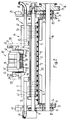
- the apron conveyor 4 is formed by a number of round aprons 5 (FIG. 2) which run parallel to one another and at a distance from one another and are guided over deflection rollers 6 and 7, of which one deflection roller is driven.
- the belt conveyor 3 and the apron conveyor 4 can have the same or different conveying speeds.
- the deflection rollers 6, 7 are rotatably mounted in two arms 8, 9 (FIG. 2) running parallel to one another.
- the apron conveyor 4 is designed as a rocker which can be pivoted about the axis 6 'of the deflection roller 6 and is supported on a piston-cylinder unit 10 which is only shown schematically in FIG. 1. By means of the latter, the pivoting position of the apron conveyor 4 is set in a manner to be described.
- a stop 11 which has a number of stop fingers 12 (FIG. 2) which are arranged at a distance from one another and each extend between two round aprons 5.
- a conveyor roller 13 is provided in front of the stop 11, which extends transversely to the conveying direction A and rests on the scale formation S.
- This conveyor roller 13 is rotatably supported on both ends in an arm 14 or 15 by means of bearings 16, 17 (FIG. 2).
- the arms 14, 15 are in turn supported at the other end on a shaft 18 by means of self-aligning bearings 19, 20.
- the shaft 18 passes through the arms 14, 15 of the strappy conveyor 4 and is supported in bearing parts 21, 22 which are attached to the arms 14 or 15 are attached (Fig. 2).
- the shaft 18 is supported by bearings 23 and 24.
- At one end of the shaft 18 sits a gear 25, which is driven by a drive chain 26 by a drive, not shown.
- This gear 25 meshes with a gear 27, which is firmly seated on an extension 13a of the conveyor roller 13.
- the conveyor roller 13 is thus driven in a rotating manner in the direction of the arrow T (FIG. 3).
- the conveyor roller 13 exerting a conveying effect on the printed products 2 can adapt to the changing height of the scale formation S thanks to its oscillating mounting. Since the two bearing arms 14, 15 for the drive roller 13 are pivoted independently of one another, as described, the conveyor roller 13 can also adapt if differences in thickness occur in the scale formation S in a direction transverse to the conveying direction A.
- a stacking point 28 is defined between the conveyor roller 13 and the stop 11, at which the printed products 2 are stacked up to form an intermediate stack 29.
- a support plate 30 (FIG. 2) is arranged below the round apron 5, which prevents the round aprons 5 from bending under the weight of the intermediate stack 29.
- the printed products 2 are pushed into the intermediate stack 29 from below by the apron conveyor 4.
- the driven conveyor roller 13 supports the insertion of the printed products 2 into the intermediate stack 29.
- the stop 11 slows the feed movement of the printed products 2.
- a height monitoring arrangement is shown purely schematically, the z. B. can be designed as a light barrier.
- This height monitoring arrangement 31 is connected to a control arrangement, not shown, which controls the cylinder-piston unit 10 and thus the swivel position of the apron conveyor 4.
- This height monitoring arrangement 31 ensures that the upper side 29a of the intermediate stack 29 is always at approximately the same level H. This is achieved in that when the height of the intermediate stack 29 changes, the apron conveyor 4 is pivoted upwards or downwards by means of the piston-cylinder unit 10 in order to keep the top side 29a of the stack at the desired height H.
- apron conveyor 4 there is a second conveyor device 32 which has individually controllable grippers 33, which are attached at regular intervals to an endless chain, not shown, which is guided in a chain channel 34.
- the chain and thus also the grippers 33 run in the direction of arrow B (FIG. 1).
- Each gripper 33 has a support element 35 fastened to the chain, on which a clamping plate 36 and two clamping fingers 37 cooperating therewith are pivotably mounted.
- the two clamping fingers 37 which are arranged at a distance from one another are under the action of a closing spring 38 which presses the clamping finger 37 against the clamping plate 36 and thus keeps the gripper 33 closed.
- the two closing springs 38 are arranged on a bolt 39 which is mounted in the support element 35 and around the longitudinal axis of which the clamping plate 36 can be freely pivoted together with the associated clamping fingers 37.
- a control arm 40 is connected to each clamping finger 37 and carries a control roller 41 at its end.
- the clamping plates 36 are provided with a shoulder 36a, which is directed backwards in the conveying direction B and is intended to interact with a positioning link 42.
- an opening guide 43 is used, which cooperates with the control roller 41 and causes the clamping fingers 37 to be lifted against the force of the closing springs 38 from the clamping plate 36.
- a suction device arrangement In order to bring the printed products 2 from the intermediate stack 29 into the conveying area F of the conveying device 32, ie into the movement path of the opened grippers 33, a suction device arrangement, generally designated 44, is provided.
- This has two suction heads 45 and 46 arranged at a distance from one another (FIG. 2), each of which is fastened to a tubular support arm 47.
- a connecting hose 48 is connected to each support arm, which is connected to a vacuum source, not shown, which can be switched on and off periodically.
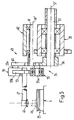
- Each support arm 47 is further connected to a drive 49, only partially shown in FIG. 2, which will be explained in more detail with reference to FIGS. 4 and 5.
- this drive 49 By means of this drive 49, the suction heads 45, 46 are moved along a closed, approximately pear-shaped orbit 50.
- these orbits 50 run to the side of the conveyor 32.
- Each orbit 50 runs from a takeover point 51, which is located on the top of the stack 29a in the area of the trailing fold edge 2a of the printed products 2, up to a delivery point 52 and then on upwards and in a loop back to the transfer point 51.
- the suction heads 45, 46 are connected to the vacuum source. This means that the uppermost printed product 2 'in the intermediate stack 29 in the area of the fold 2a is gripped by the suction heads 45, 46 and taken upwards into the conveying area F of the conveying device 32.
- the folded edges 2a of the printed products 2 which are lifted upwards by the suction heads 45, 46 are thus brought into the path of movement of an open gripper 33 each and come between its clamping plate 36 and the clamping fingers 37 lifted therefrom.
- the grippers 33 are brought into the suitable pivot position by means of the positioning link 42. How especially out 3 can be seen, the clamping plate 36 with the clamping fingers 37 are pivoted by means of the positioning link 42 during the takeover of the printed products 2, so that a correct gripping of the printed products 2 in the area of their fold 2a is ensured by the grippers 33.
- the tubular support arm 47 to which the suction head 45 is attached, is attached to one arm 53a of a two-armed lever 53, the other arm 53b of which is angled relative to the arm 53a.
- the arm 53b forms the coupling of a crank arm 54 and is connected to a crank 56 via a joint 55, the joint pin of which is designated 55a.
- the latter is seated on a shaft 57 which is driven in the direction of arrow D and rotates in a bearing 58 is rotatably mounted.
- the shaft 57 the longitudinal axis of which is designated 57 ', is driven by a drive device, not shown.
- the arm 53b of the lever 53 is connected to a rocker arm 60 via a joint 59, the joint pin of which is designated 59a.
- the latter is attached to a shaft 61, which is freely rotatably mounted in a bearing 62.
- the longitudinal axis of this shaft 61 is designated 61 '.
- the rocker 60 With the crank 56 rotating, the rocker 60 is pivoted back and forth between two end positions, which are shown in broken lines in FIG. 4 and form an angle ⁇ .
- the two end positions of the rocker arm 60 are designated by the positions of the pivot pin 59a, designated 59a ′ and 59a ′′.
- the suction head 45 is now moved upward from the takeover point 51 along the section 50a of the orbit 50 to the delivery point 52. Between the take-over point 51 and the delivery point 52, the suction head 45 is, as already mentioned, connected to the vacuum source and takes a printed product 2 with it. After switching off the vacuum source, the printed product is released. The suction head 45 is moved further in the direction of the arrow C along the orbit 50 until it arrives again at the takeover point 51, where the next printed product 2 is detected. It is obvious that the orbit 50 is selected such that the suction head 45 runs around the printed product 2 after it has been released, so that the gripper 33 grips the printed product by the suction head movement is not affected.
- the printed products 2 fed in by the belt conveyor 3 in scale formation S are subsequently conveyed with the folded edge 2a to the stacking point 28 and are inserted there at the bottom with the support of the conveying roller 13 into the intermediate stack 29.
- the uppermost printed product 2 in the intermediate stack 29 is captured by the suction heads 45, 46 in the region of the folded edge 2a and lifted upwards from the intermediate stack 29.
- the folded edge 2a is brought into the path of movement of the open grippers 33 and clamped between the clamping plate 36 and the clamping fingers 37.
- the grippers 33 are closed by the closing springs 38 after the control roller 41 has run off the opening link 43.
- the printed products 2 gripped by the grippers 33 are then completely lifted off the intermediate stack 29 and guided upwards to a further processing point (not shown).
- the open side edge 2b of the printed products 2 leading in the supplied scale formation S and covered by the leading printed product is exposed after being taken over by the conveyor device 32, which means that the folded printed products can be opened while they are still being held by
- the suction arrangement 44 is designed such that the suction heads 45, 46 act on the printed products 2 in the area of the fold 2a as described.
- the scale formation S is produced differently than as shown in FIG. 1, ie with the fold 2a of the printed products as the leading edge lying at the bottom, the scale formation S would have to be fed to the stacking point 28 from the other side.
- This variant is shown in dot-dash lines in FIG. 1 on the right-hand side.
- the Belt conveyor 3 ' conveys the scale formation S', in which each printed product 2 still rests on the trailing printed product, but the leading edge is the folded edge 2a, in the direction of arrow A ', which is opposite to the conveying direction A of the belt conveyor 3.
- the suction arrangement 44 and the conveying device 32 remain the same, but the apron conveyor 4 has to be pivoted about the axis 7 'of the deflecting roller 7 instead of about the axis 6'.
- stop 11 and conveyor roller 13 are to be exchanged for one another, as is evident from FIG. 1.
- the gripping and feeding of the printed products 2 into the conveying area F of the grippers 33 is the same as already described with reference to FIG. 1.
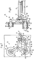
- FIG. 6 is very similar to the embodiment according to FIGS. 1-3 and differs from the latter only in a different configuration of the suction arrangement and the delivery of the printed products 2 from the intermediate stack 29 to the grippers 33 corresponding parts use the same reference numerals as in FIGS. 1-3.
- the device according to FIG. 6 is used to process printed products 2 which take up a different position within the supplied scale formation S than in the scale formation S which is fed to the device according to FIGS. 1-3.
- each printed product 2 in the scale formation S fed by the belt conveyor 3, each printed product 2 also rests on the subsequent printed product.
- the leading and thus hidden edges of the printed products 2 in contrast to the scale formation S shown in FIG. 1, formed by the folded edges 2a.
- the printed products 2 must be grasped by the suction arrangement designated 65 in FIG. 6 in the region of their edge 2a abutting the stop 11.
- the printed products 2 are not introduced into the grippers 33 with their folded edge 2a, but with their opposite open side edge 2b.
- the suction arrangement 65 has two suction heads 66 that operate synchronously or at most in push-pull, of which only one suction head is shown in FIG. 6. This is moved by means of a drive to be described in more detail between a takeover point 67, at which it grips a printed product 2, and a delivery point 68, at which the detected product 2 is released, along the movement path designated by 70.
- the suction head 66 is connected to a vacuum source, as described earlier, and lifts the uppermost printed product 2 from the intermediate stack 29 and pushes it back against the conveying direction A in the direction of arrow E against the conveying device 32.
- a guide element 71 is provided on the edge of the intermediate stack 29 opposite the stop 11, which guides the edge 2b leading when the printed products 2 move back diverted upwards into the mentioned funding area F.
- the suction head 66 is attached to a tubular support arm 72, which is connected via a hose line to a vacuum source, not shown.
- This support arm 72 is connected to a drive 73 which has a lever 75 with which the support arm 72 is fixedly connected.
- This lever 75 is connected at both ends via joints 76 and 77 to other levers.
- the joint 76 By means of the joint 76, the axis of which is denoted by 76 ', the lever 75 is connected to a lever 78 which is non-rotatably seated on a shaft 79 with the axis 79' which is pivotably mounted in a bearing 80.
- the lever 75 is connected to a further lever 81, which is pivotably mounted in a bearing 82.
- the two-armed lever 81 is connected at the other end via a further joint 83 to the coupling 84 of a crank drive, which is connected to a crank 86 via a joint 85.
- the latter sits on a shaft 87 with the axis 87 ', which is mounted in a bearing 88 and is connected to a drive, not shown.
- the crank 86 rotates in the direction of the arrow K.
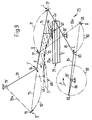
- FIG. 9 shows the lever transmission described above only schematically.
- the connecting joint 85 between the crank 86 and the coupling 84 runs along a circular path 89.
- the lever 81 performs a pivoting movement about the axis 82 'of its bearing 82.
- the Both end positions of the lever 81 are shown on the one hand with a solid line and on the other hand with a dash-dotted line.
- the two joints 77 and 83 of the lever 81 move back and forth along the tracks 90 and 91 between the points I and II.
- the lever 78 swings from the position shown with a solid line to the position 78a shown in broken lines and back again, the joint 76 moving back and forth along the path 92 between points I 'and II'.
- a variant is indicated with dash-dotted lines, comparable to FIG. 1, in which the belt conveyor 3 'conveys the scale formation S' in a direction A 'to the stacking point 28, which is opposite to the conveying direction A of the belt conveyor 3.
- This variant is used when the folded edge 2a in the supplied scale formation S 'is the trailing, top edge.
- the stop 11 and the conveying roller 13 the guide member 71 and the height monitoring arrangement 31 have to be exchanged.
- the apron conveyor 4 must be pivotally mounted about the axis 7a of the deflection roller 7. In contrast, nothing needs to be changed on the suction arrangement 65.
- FIG. 10 shows a third embodiment of the device according to the invention, which is very similar to the embodiment according to FIG. 6 and differs from it only in a different design of the second conveying device.
- the conveyor device 93 is formed by two belt conveyors 94 and 95 arranged one above the other, which form a conveyor gap 96 between them.
- the conveying direction of the conveying device 93 is designated by L.
- the uppermost printed product 2 in the intermediate stack 29 is slightly lifted from the stack 29 by the suction arrangement 65, as described in connection with FIGS. 6-9, and pushed back in the direction of the arrow E.
- the leading, open edge 2b of the printed products 2 is deflected by the guide element 71 into the inlet 96a of the conveyor gap 96.
- the printed products 2 are conveyed away again by the conveying device 93 in a scale formation S 1, in which each printed product 2 rests on the subsequent printed product.
- the leading edge 2 b is formed by the edge that formed the trailing edge in the shingled stream S supplied.
- the apron conveyor can 4 run approximately horizontally (as shown in FIG. 1) or, as shown in FIGS. 6 and 10, are inclined sloping in the conveying direction.
Landscapes
- Engineering & Computer Science (AREA)
- Mechanical Engineering (AREA)
- Feeding Of Articles By Means Other Than Belts Or Rollers (AREA)
- Folding Of Thin Sheet-Like Materials, Special Discharging Devices, And Others (AREA)
- Separation, Sorting, Adjustment, Or Bending Of Sheets To Be Conveyed (AREA)
- Discharge By Other Means (AREA)
- Sheets, Magazines, And Separation Thereof (AREA)
- Delivering By Means Of Belts And Rollers (AREA)
- Ultra Sonic Daignosis Equipment (AREA)
- Stringed Musical Instruments (AREA)
- Diaphragms For Electromechanical Transducers (AREA)
- Making Paper Articles (AREA)
- Coloring (AREA)
Applications Claiming Priority (3)
| Application Number | Priority Date | Filing Date | Title |
|---|---|---|---|
| CH4692 | 1992-01-09 | ||
| CH46/92 | 1992-01-09 | ||
| SG141794A SG141794G (en) | 1992-01-09 | 1994-10-01 | Process and apparatus for delivering preferably folded printing products to a further processing point |
Publications (2)
| Publication Number | Publication Date |
|---|---|
| EP0551601A1 true EP0551601A1 (fr) | 1993-07-21 |
| EP0551601B1 EP0551601B1 (fr) | 1996-06-05 |
Family
ID=25683350
Family Applications (1)
| Application Number | Title | Priority Date | Filing Date |
|---|---|---|---|
| EP92120375A Expired - Lifetime EP0551601B1 (fr) | 1992-01-09 | 1992-11-28 | Dispositif et procédé pour l'alimentation spécialement de produits imprimés pliés vers un autre poste de travail |
Country Status (17)
| Country | Link |
|---|---|
| US (1) | US5398920A (fr) |
| EP (1) | EP0551601B1 (fr) |
| JP (1) | JP2928038B2 (fr) |
| KR (1) | KR970000773B1 (fr) |
| AT (1) | ATE138886T1 (fr) |
| AU (1) | AU645716B2 (fr) |
| BR (1) | BR9205180A (fr) |
| CA (1) | CA2086633C (fr) |
| DE (1) | DE59206494D1 (fr) |
| DK (1) | DK0551601T3 (fr) |
| ES (1) | ES2088075T3 (fr) |
| FI (1) | FI106250B (fr) |
| GB (1) | GB2260123B (fr) |
| HK (1) | HK133994A (fr) |
| NO (1) | NO302286B1 (fr) |
| RU (1) | RU2067540C1 (fr) |
| SG (1) | SG141794G (fr) |
Cited By (10)
| Publication number | Priority date | Publication date | Assignee | Title |
|---|---|---|---|---|
| DE4241885C1 (de) * | 1992-10-05 | 1993-11-25 | Ferag Ag | Regelanordnung für eine Vorrichtung zum Zubringen von Druckereierzeugnissen zu einer Weiterverarbeitungsstelle |
| EP0709218A1 (fr) | 1994-10-27 | 1996-05-01 | Ferag AG | Procédé et dispositif pour marquer des produits imprimés |
| EP0755886A1 (fr) * | 1995-07-25 | 1997-01-29 | Ferag AG | Dispositif pour alimenter des produits imprimés à une station de traitement ultérieure |
| US5636832A (en) * | 1994-03-24 | 1997-06-10 | Ferag Ag | Apparatus for feeding sheet-like products to a discharge location |
| EP0806391A1 (fr) * | 1996-05-06 | 1997-11-12 | Ferag AG | Dispositif pour l'alimentation de produits imprimés vers un autre poste de travail |
| DE19515506B4 (de) * | 1994-05-31 | 2004-11-18 | Ferag Ag | Einrichtung zum Verarbeiten von Druckereiprodukten |
| DE19627490B4 (de) * | 1995-07-27 | 2005-02-24 | Ferag Ag | Fördereinrichtung für Druckereierzeugnisse |
| DE19603040B4 (de) * | 1995-03-31 | 2006-05-24 | Ferag Ag | Saugorgan |
| EP1834913A1 (fr) * | 2006-03-17 | 2007-09-19 | Ferag AG | Dispositif pour ramasser et convoyer des produits plats |
| EP2017209A1 (fr) * | 2007-07-17 | 2009-01-21 | Müller Martini Holding AG | Procédé et dispositif pour transférer des produits imprimés transportés en formation imbriquée à un convoyeur sans fin muni de pinces |
Families Citing this family (13)
| Publication number | Priority date | Publication date | Assignee | Title |
|---|---|---|---|---|
| DE59403428D1 (de) * | 1993-05-21 | 1997-08-28 | Ferag Ag | Einrichtung zum Vereinzeln gestapelter Druckereiprodukte |
| ATE167452T1 (de) * | 1993-06-29 | 1998-07-15 | Ferag Ag | Vorrichtung zum zubringen von erzeugnissen, wie karten und warenproben, zu einer weiterverarbeitungsstelle |
| GB9508478D0 (en) * | 1995-04-26 | 1995-06-14 | Rensen Alan M S | Feeder for sheet form elements |
| DE19627830B4 (de) * | 1995-07-31 | 2005-07-28 | Ferag Ag | Vorrichtung zum Zubringen von Druckereiprodukten zu einem Wegförderer |
| US5819663A (en) * | 1995-09-06 | 1998-10-13 | Quad/Tech, Inc. | Gripper conveyor with preliminary ink jet |
| EP0863099B1 (fr) * | 1997-03-04 | 2001-11-21 | Ferag AG | Dispositif pour séparer des produits imprimés empilés |
| CH692617A5 (de) * | 1998-02-27 | 2002-08-30 | Ferag Ag | Vorrichtung zum Verarbeiten von flexiblen, flächigen Erzeugnissen. |
| US6748294B1 (en) * | 2000-10-23 | 2004-06-08 | Bowe Bell + Howell Postal Systems Company | Flats bundle collator |
| ATE337997T1 (de) * | 2002-05-22 | 2006-09-15 | Ferag Ag | Verfahren zum fördern von flächigen, flexiblen produkten und vorrichtung zur durchführung des verfahrens |
| US6755412B1 (en) | 2002-07-23 | 2004-06-29 | Charles Dwayne Glowner | High speed overlapping insert feeding assembly |
| ATE525318T1 (de) * | 2005-11-01 | 2011-10-15 | Ferag Ag | Verfahren und vorrichtung zum umlagern von flächigen erzeugnissen von einem erzeugnisstapel auf ein förderband |
| JP5041553B2 (ja) * | 2006-04-12 | 2012-10-03 | フェラーク・アクチェンゲゼルシャフト | 平坦な物体を把持し搬送するためのグリッパ |
| DE102010043063B4 (de) * | 2010-10-28 | 2012-11-08 | Böwe Systec Gmbh | Vorrichtung und Verfahren zum Puffern einer Mehrzahl von Gütern oder Gutgruppen und Papierhandhabungsanlage mit derselben |
Citations (2)
| Publication number | Priority date | Publication date | Assignee | Title |
|---|---|---|---|---|
| EP0330868A1 (fr) * | 1988-03-03 | 1989-09-06 | Ferag AG | Procédé et dispositif d'évacuation de produits imprimés, qui sont amenés en formation en écailles |
| EP0368009A1 (fr) * | 1988-11-11 | 1990-05-16 | Ferag AG | Procédé et dispositif pour délivrer des articles d'imprimerie |
Family Cites Families (11)
| Publication number | Priority date | Publication date | Assignee | Title |
|---|---|---|---|---|
| GB489963A (en) * | 1936-03-05 | 1938-08-08 | John Dickinson & Company Ltd | Improvements in or relating to envelope making machines |
| US3255652A (en) * | 1963-09-16 | 1966-06-14 | Miehle Goss Dexter Inc | Apparatus for handling sheets |
| JPS5216434B2 (fr) * | 1971-09-20 | 1977-05-09 | ||
| NL7312656A (nl) * | 1973-09-13 | 1975-03-17 | Packotom B V | Inrichting voor het stapelen van losse vellen. |
| CH630583A5 (de) * | 1978-06-30 | 1982-06-30 | Ferag Ag | Vorrichtung zum wegfoerdern von in einem schuppenstrom anfallenden flaechigen erzeugnissen, insbesondere druckprodukten. |
| US4369959A (en) * | 1979-11-10 | 1983-01-25 | Hornbuckle William M | Sheet feed machine |
| JPS5914452Y2 (ja) * | 1981-10-20 | 1984-04-27 | 株式会社篠原鉄工所 | 枚葉印刷機の給紙装置 |
| US4478400A (en) * | 1982-05-19 | 1984-10-23 | Suburban Duplicator Repair, Inc. | Envelope feeder for a duplicating press |
| GB2205819A (en) * | 1987-06-17 | 1988-12-21 | Hiroshi Harada | Envelope feeder |
| US4762314A (en) * | 1987-06-17 | 1988-08-09 | Hiroshi Harada | Envelope feeder |
| US4805890A (en) * | 1987-08-06 | 1989-02-21 | Merrill David Martin | Sheet stacking machine |
-
1992
- 1992-11-26 AU AU29683/92A patent/AU645716B2/en not_active Ceased
- 1992-11-26 GB GB9224763A patent/GB2260123B/en not_active Expired - Fee Related
- 1992-11-28 DK DK92120375.8T patent/DK0551601T3/da active
- 1992-11-28 AT AT92120375T patent/ATE138886T1/de active
- 1992-11-28 ES ES92120375T patent/ES2088075T3/es not_active Expired - Lifetime
- 1992-11-28 EP EP92120375A patent/EP0551601B1/fr not_active Expired - Lifetime
- 1992-11-28 DE DE59206494T patent/DE59206494D1/de not_active Expired - Lifetime
- 1992-12-21 KR KR1019920024934A patent/KR970000773B1/ko not_active IP Right Cessation
- 1992-12-29 BR BR9205180A patent/BR9205180A/pt not_active IP Right Cessation
- 1992-12-29 US US07/997,886 patent/US5398920A/en not_active Expired - Lifetime
-
1993
- 1993-01-04 CA CA002086633A patent/CA2086633C/fr not_active Expired - Fee Related
- 1993-01-06 RU RU9393004437A patent/RU2067540C1/ru not_active IP Right Cessation
- 1993-01-07 FI FI930045A patent/FI106250B/fi not_active IP Right Cessation
- 1993-01-08 NO NO930057A patent/NO302286B1/no not_active IP Right Cessation
- 1993-01-08 JP JP5001704A patent/JP2928038B2/ja not_active Expired - Fee Related
-
1994
- 1994-10-01 SG SG141794A patent/SG141794G/en unknown
- 1994-12-01 HK HK133994A patent/HK133994A/xx not_active IP Right Cessation
Patent Citations (2)
| Publication number | Priority date | Publication date | Assignee | Title |
|---|---|---|---|---|
| EP0330868A1 (fr) * | 1988-03-03 | 1989-09-06 | Ferag AG | Procédé et dispositif d'évacuation de produits imprimés, qui sont amenés en formation en écailles |
| EP0368009A1 (fr) * | 1988-11-11 | 1990-05-16 | Ferag AG | Procédé et dispositif pour délivrer des articles d'imprimerie |
Cited By (14)
| Publication number | Priority date | Publication date | Assignee | Title |
|---|---|---|---|---|
| US5419678A (en) * | 1992-10-05 | 1995-05-30 | Ferag Ag | Control arrangement for an apparatus for delivering printing products |
| DE4241885C1 (de) * | 1992-10-05 | 1993-11-25 | Ferag Ag | Regelanordnung für eine Vorrichtung zum Zubringen von Druckereierzeugnissen zu einer Weiterverarbeitungsstelle |
| US5636832A (en) * | 1994-03-24 | 1997-06-10 | Ferag Ag | Apparatus for feeding sheet-like products to a discharge location |
| DE19515506B4 (de) * | 1994-05-31 | 2004-11-18 | Ferag Ag | Einrichtung zum Verarbeiten von Druckereiprodukten |
| EP0709218A1 (fr) | 1994-10-27 | 1996-05-01 | Ferag AG | Procédé et dispositif pour marquer des produits imprimés |
| DE19603040C5 (de) * | 1995-03-31 | 2012-09-13 | Ferag Ag | Saugorgan |
| DE19603040B4 (de) * | 1995-03-31 | 2006-05-24 | Ferag Ag | Saugorgan |
| EP0755886A1 (fr) * | 1995-07-25 | 1997-01-29 | Ferag AG | Dispositif pour alimenter des produits imprimés à une station de traitement ultérieure |
| AU698518B2 (en) * | 1995-07-25 | 1998-10-29 | Ferag Ag | Apparatus for delivering printed products to a further- processing location |
| DE19627490B4 (de) * | 1995-07-27 | 2005-02-24 | Ferag Ag | Fördereinrichtung für Druckereierzeugnisse |
| EP0806391A1 (fr) * | 1996-05-06 | 1997-11-12 | Ferag AG | Dispositif pour l'alimentation de produits imprimés vers un autre poste de travail |
| EP1834913A1 (fr) * | 2006-03-17 | 2007-09-19 | Ferag AG | Dispositif pour ramasser et convoyer des produits plats |
| EP2017209A1 (fr) * | 2007-07-17 | 2009-01-21 | Müller Martini Holding AG | Procédé et dispositif pour transférer des produits imprimés transportés en formation imbriquée à un convoyeur sans fin muni de pinces |
| US7784784B2 (en) | 2007-07-17 | 2010-08-31 | Mueller Martini Holding Ag | Method and apparatus for transferring printed products conveyed in an shingled flow to a transporter with circulating clamps |
Also Published As
| Publication number | Publication date |
|---|---|
| GB9224763D0 (en) | 1993-01-13 |
| DK0551601T3 (da) | 1996-07-01 |
| GB2260123B (en) | 1994-05-25 |
| SG141794G (en) | 1995-01-13 |
| CA2086633C (fr) | 1999-08-17 |
| RU2067540C1 (ru) | 1996-10-10 |
| KR930016241A (ko) | 1993-08-26 |
| HK133994A (en) | 1994-12-09 |
| NO930057D0 (no) | 1993-01-08 |
| JP2928038B2 (ja) | 1999-07-28 |
| BR9205180A (pt) | 1993-07-13 |
| ATE138886T1 (de) | 1996-06-15 |
| DE59206494D1 (de) | 1996-07-11 |
| JPH0624617A (ja) | 1994-02-01 |
| FI106250B (fi) | 2000-12-29 |
| GB2260123A (en) | 1993-04-07 |
| US5398920A (en) | 1995-03-21 |
| FI930045A (fi) | 1993-07-10 |
| AU2968392A (en) | 1993-07-15 |
| AU645716B2 (en) | 1994-01-20 |
| EP0551601B1 (fr) | 1996-06-05 |
| KR970000773B1 (ko) | 1997-01-20 |
| ES2088075T3 (es) | 1996-08-01 |
| FI930045A0 (fi) | 1993-01-07 |
| CA2086633A1 (fr) | 1993-07-10 |
| NO930057L (no) | 1993-07-12 |
| NO302286B1 (no) | 1998-02-16 |
Similar Documents
| Publication | Publication Date | Title |
|---|---|---|
| EP0551601B1 (fr) | Dispositif et procédé pour l'alimentation spécialement de produits imprimés pliés vers un autre poste de travail | |
| EP0218872B1 (fr) | Dispositif pour assembler différents produits imprimés | |
| DE3512737C2 (de) | Aufgeber von Heftlagen, Bogen und ähnlichen Erzeugnissen für Zuführvorrichtungen in Packmaschinen, Buchbindereimaschinen u.dgl. | |
| DE3608055C2 (de) | Vorrichtung zum Beschicken einer Vereinzelungseinrichtung für Druckprodukte, insbesondere eines Anlegers | |
| EP0330868B1 (fr) | Procédé et dispositif d'évacuation de produits imprimés, qui sont amenés en formation en écailles | |
| CH630583A5 (de) | Vorrichtung zum wegfoerdern von in einem schuppenstrom anfallenden flaechigen erzeugnissen, insbesondere druckprodukten. | |
| DE1761688B2 (de) | Transporteinrichtung für in einer Schuppenformation anfallende, flächenhafte Gebilde | |
| EP0368009B1 (fr) | Procédé et dispositif pour délivrer des articles d'imprimerie | |
| EP0305671B1 (fr) | Convoyeur pour des imprimés et application du convoyeur | |
| EP0564812B1 (fr) | Procédé et dispositif pour ouvrir des produits d'imprimerie pliés | |
| EP0522319B1 (fr) | Procédé et dispositif pour ouvrir des articles flexible pliés hors du centre | |
| DE3306815C2 (de) | Vorrichtung zum transportieren von in einer schuppenformation anfallenden flaechigen erzeugnissen, insbesondere druckprodukten | |
| EP0553455B1 (fr) | Procédé et dispositif pour enlever des produits imprimés d'une pile | |
| EP0242702B1 (fr) | Procédé et dispositif pour tourner des objets plats | |
| EP0600216B1 (fr) | Procédé et dispositif pour ouvrir des produits d'imprimerie pliés | |
| DE2058606A1 (de) | Verfahren und Vorrichtung zum seitlichen Ausrichten von Blaettern,insbesondere bei einer Druckpresse | |
| EP0300171B1 (fr) | Dispositif de transport pour produits plats, en particulier des produits imprimés | |
| EP0218804B1 (fr) | Dispositif pour reprendre et transférer des feuilles pliées d'un dispositif de transport | |
| EP0518064B1 (fr) | Procédé et appareil pour la manutention de produits imprimés | |
| WO2000024660A1 (fr) | Procede et dispositif d'alimentation en imprimes | |
| EP1072546B1 (fr) | Convoyeur pour assembler et traiter des produits imprimés | |
| EP0863099B1 (fr) | Dispositif pour séparer des produits imprimés empilés | |
| DE2440106A1 (de) | Vorrichtung zum auftragen von klebstoff | |
| DE19509487C1 (de) | Bogenanleger | |
| EP1310443A2 (fr) | Margeur |
Legal Events
| Date | Code | Title | Description |
|---|---|---|---|
| PUAI | Public reference made under article 153(3) epc to a published international application that has entered the european phase |
Free format text: ORIGINAL CODE: 0009012 |
|
| AK | Designated contracting states |
Kind code of ref document: A1 Designated state(s): AT BE CH DE DK ES FR IT LI NL SE |
|
| 17P | Request for examination filed |
Effective date: 19930830 |
|
| 17Q | First examination report despatched |
Effective date: 19941213 |
|
| GRAH | Despatch of communication of intention to grant a patent |
Free format text: ORIGINAL CODE: EPIDOS IGRA |
|
| GRAH | Despatch of communication of intention to grant a patent |
Free format text: ORIGINAL CODE: EPIDOS IGRA |
|
| GRAA | (expected) grant |
Free format text: ORIGINAL CODE: 0009210 |
|
| AK | Designated contracting states |
Kind code of ref document: B1 Designated state(s): AT BE CH DE DK ES FR IT LI NL SE |
|
| REF | Corresponds to: |
Ref document number: 138886 Country of ref document: AT Date of ref document: 19960615 Kind code of ref document: T |
|
| REG | Reference to a national code |
Ref country code: CH Ref legal event code: NV Representative=s name: SCHAAD, BALASS & PARTNER AG |
|
| REG | Reference to a national code |
Ref country code: ES Ref legal event code: BA2A Ref document number: 2088075 Country of ref document: ES Kind code of ref document: T3 |
|
| REG | Reference to a national code |
Ref country code: DK Ref legal event code: T3 |
|
| REF | Corresponds to: |
Ref document number: 59206494 Country of ref document: DE Date of ref document: 19960711 |
|
| ITF | It: translation for a ep patent filed |
Owner name: SOCIETA' ITALIANA BREVETTI S.P.A. |
|
| REG | Reference to a national code |
Ref country code: ES Ref legal event code: FG2A Ref document number: 2088075 Country of ref document: ES Kind code of ref document: T3 |
|
| ET | Fr: translation filed | ||
| PLBE | No opposition filed within time limit |
Free format text: ORIGINAL CODE: 0009261 |
|
| STAA | Information on the status of an ep patent application or granted ep patent |
Free format text: STATUS: NO OPPOSITION FILED WITHIN TIME LIMIT |
|
| 26N | No opposition filed | ||
| REG | Reference to a national code |
Ref country code: CH Ref legal event code: PFA Owner name: FERAG AG Free format text: FERAG AG##CH-8340 HINWIL (CH) -TRANSFER TO- FERAG AG#PATENTABTEILUNG Z. H. MARKUS FELIX ZUERICHSTRASSE 74#8340 HINWIL (CH) |
|
| PGFP | Annual fee paid to national office [announced via postgrant information from national office to epo] |
Ref country code: ES Payment date: 20091123 Year of fee payment: 18 |
|
| PGFP | Annual fee paid to national office [announced via postgrant information from national office to epo] |
Ref country code: FR Payment date: 20101130 Year of fee payment: 19 Ref country code: AT Payment date: 20101112 Year of fee payment: 19 Ref country code: NL Payment date: 20101111 Year of fee payment: 19 |
|
| PGFP | Annual fee paid to national office [announced via postgrant information from national office to epo] |
Ref country code: DE Payment date: 20101119 Year of fee payment: 19 |
|
| PGFP | Annual fee paid to national office [announced via postgrant information from national office to epo] |
Ref country code: BE Payment date: 20101117 Year of fee payment: 19 Ref country code: IT Payment date: 20101126 Year of fee payment: 19 |
|
| REG | Reference to a national code |
Ref country code: ES Ref legal event code: FD2A Effective date: 20120110 |
|
| PG25 | Lapsed in a contracting state [announced via postgrant information from national office to epo] |
Ref country code: ES Free format text: LAPSE BECAUSE OF NON-PAYMENT OF DUE FEES Effective date: 20101129 |
|
| PGFP | Annual fee paid to national office [announced via postgrant information from national office to epo] |
Ref country code: SE Payment date: 20111128 Year of fee payment: 20 Ref country code: CH Payment date: 20111116 Year of fee payment: 20 Ref country code: DK Payment date: 20111118 Year of fee payment: 20 |
|
| BERE | Be: lapsed |
Owner name: *FERAG A.G. Effective date: 20111130 |
|
| REG | Reference to a national code |
Ref country code: NL Ref legal event code: V1 Effective date: 20120601 |
|
| PG25 | Lapsed in a contracting state [announced via postgrant information from national office to epo] |
Ref country code: NL Free format text: LAPSE BECAUSE OF NON-PAYMENT OF DUE FEES Effective date: 20120601 |
|
| REG | Reference to a national code |
Ref country code: FR Ref legal event code: ST Effective date: 20120731 |
|
| PG25 | Lapsed in a contracting state [announced via postgrant information from national office to epo] |
Ref country code: IT Free format text: LAPSE BECAUSE OF NON-PAYMENT OF DUE FEES Effective date: 20111128 Ref country code: BE Free format text: LAPSE BECAUSE OF NON-PAYMENT OF DUE FEES Effective date: 20111130 |
|
| REG | Reference to a national code |
Ref country code: DE Ref legal event code: R071 Ref document number: 59206494 Country of ref document: DE |
|
| REG | Reference to a national code |
Ref country code: DE Ref legal event code: R071 Ref document number: 59206494 Country of ref document: DE |
|
| REG | Reference to a national code |
Ref country code: CH Ref legal event code: PL |
|
| REG | Reference to a national code |
Ref country code: AT Ref legal event code: MM01 Ref document number: 138886 Country of ref document: AT Kind code of ref document: T Effective date: 20111128 |
|
| PG25 | Lapsed in a contracting state [announced via postgrant information from national office to epo] |
Ref country code: FR Free format text: LAPSE BECAUSE OF NON-PAYMENT OF DUE FEES Effective date: 20111130 |
|
| REG | Reference to a national code |
Ref country code: SE Ref legal event code: EUG |
|
| PG25 | Lapsed in a contracting state [announced via postgrant information from national office to epo] |
Ref country code: AT Free format text: LAPSE BECAUSE OF NON-PAYMENT OF DUE FEES Effective date: 20111128 |