EP0551132B1 - Sequence controller including error correction and method therefor - Google Patents
Sequence controller including error correction and method therefor Download PDFInfo
- Publication number
- EP0551132B1 EP0551132B1 EP93100220A EP93100220A EP0551132B1 EP 0551132 B1 EP0551132 B1 EP 0551132B1 EP 93100220 A EP93100220 A EP 93100220A EP 93100220 A EP93100220 A EP 93100220A EP 0551132 B1 EP0551132 B1 EP 0551132B1
- Authority
- EP
- European Patent Office
- Prior art keywords
- sequence
- program
- step number
- stop
- executed
- Prior art date
- Legal status (The legal status is an assumption and is not a legal conclusion. Google has not performed a legal analysis and makes no representation as to the accuracy of the status listed.)
- Expired - Lifetime
Links
Images


Classifications
-
- G—PHYSICS
- G05—CONTROLLING; REGULATING
- G05B—CONTROL OR REGULATING SYSTEMS IN GENERAL; FUNCTIONAL ELEMENTS OF SUCH SYSTEMS; MONITORING OR TESTING ARRANGEMENTS FOR SUCH SYSTEMS OR ELEMENTS
- G05B19/00—Programme-control systems
- G05B19/02—Programme-control systems electric
- G05B19/04—Programme control other than numerical control, i.e. in sequence controllers or logic controllers
- G05B19/05—Programmable logic controllers, e.g. simulating logic interconnections of signals according to ladder diagrams or function charts
- G05B19/058—Safety, monitoring
-
- G—PHYSICS
- G05—CONTROLLING; REGULATING
- G05B—CONTROL OR REGULATING SYSTEMS IN GENERAL; FUNCTIONAL ELEMENTS OF SUCH SYSTEMS; MONITORING OR TESTING ARRANGEMENTS FOR SUCH SYSTEMS OR ELEMENTS
- G05B2219/00—Program-control systems
- G05B2219/10—Plc systems
- G05B2219/13—Plc programming
- G05B2219/13081—Select between initialisation and normal control instructions sequence plc
-
- G—PHYSICS
- G05—CONTROLLING; REGULATING
- G05B—CONTROL OR REGULATING SYSTEMS IN GENERAL; FUNCTIONAL ELEMENTS OF SUCH SYSTEMS; MONITORING OR TESTING ARRANGEMENTS FOR SUCH SYSTEMS OR ELEMENTS
- G05B2219/00—Program-control systems
- G05B2219/10—Plc systems
- G05B2219/13—Plc programming
- G05B2219/13085—Plc controls several machines in sequence
Definitions
- the present invention relates to a sequence control system comprising a sequence controller for sequence controlling an object under a sequence control program, and a process sequence operation table, a currently executed step number table, a step operation program table and a transition condition program table for executing the sequence control program under the sequence controller.
- the invention further relates to a sequence controlling method for executing a sequence control program for sequence-controlling an object in a control system comprising a sequence controller, a process sequence operation table, a currently executed step number table, a step operation program table and a transition condition program table for executing the sequence control program under the sequence controller.
- a programmable controller for executing sequential function chart language programs.
- a programmable controller comprises means for keeping track of the next step to be executed in the program running therein and for storing this data in a discrete location. Head addresses corresponding to the steps are stored in a table which acts as a pointer to the program corresponding to active means. Further means are provided to keep track of transition criteria for moving from one step to the next, and a table is maintained containing data on the number of the steps which will be subsequently active and the corresponding step identification numbers, which serves as a map of the transits between the steps.
- the document EP-A-0 208 997 discloses a control system and a method with diagnostic logic.
- the conventional system and method is provided for controlling operation of a plurality of elements in an automated process, such as a production process, and indicating error conditions as they occur.
- Each specific set of input and output conditions of the various system elements defines a specific logic state or zone.
- a pre-determined sequence of zones, productive zones representing designed machine operations is stored in a zone table. All zones not explicitely defined in the zone table are automatically treated as error zones.
- a zone engine automatically cycles to observe any change in input/output image. Any change in inputs from the various system elements automatically transfers action to the specific zone associated with such inputs, resulting in corresponding changes in control outputs to the system elements and/or display an error message as appropriate.
- Sequential Function Chart programs or so-called SFC programs are frequently used as sequence control programs and this abbreviation will be used in the following text.
- Fig. 7 is a block diagram illustrating the arrangement of a conventional sequence controller using an SFC program as a sequence program, wherein the numeral 1 indicates a sequence controller, and 2 a controlled object.
- Reference numeral 3 indicates a table comprising a process sequence operation stable 31, a currently executed step number storage table 32, a step operation program storage table 33 and a transition condition program storage table 34 which will be described later.
- a process sequence controlling section 4 acts as a process sequence controller.
- Numeral 7 indicates input and output signals to and from the sequence controller 1.
- the sequence controller 1 comprises a CPU, a memory and an I/O interface, etc. (not separately shown), on a hardware basis.
- the process sequence controlling section 4, serving as a process sequence controller implements functions which are generated when the CPU executes a process sequence control program (an SFC program executing program) stored in the memory.
- the table 3 and other data such as the sequence program are stored in the memory.
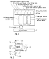
- Fig. 8 illustrates an example of a controlled object 2 controlled by the sequence controller 1, wherein 50 indicates a base, 51 and 52 a workpiece A and a workpiece B, respectively, 53 a clamper for the workpiece A 51 or the workpiece B 52, and 54 and 55 a drive motor A and a drive motor B, respectively, provided with machining means for machining the workpiece A 51 or the workpiece B 52.
- Reference numerals 56-58 indicate limit switches which normally remain OFF (hereinafter referred to as LS1, LS2, LS3, respectively).
- LS1 56 is turned ON by clamper 53 when workpiece B is set.
- LS2 57 is turned ON by clamper 53 when workpiece A is set and LS3 58 is turned ON by clamper 53 when workpieces are not set.
- Reference numbers 59 and 60 designate position detection optical sensors (hereinafter referred to as L1 and L2 respectively) to detect how far the workpieces A 51 and B 52 are shifted from their correct positions, respectively.
- L1 59 By receiving the light from an optical (light) source (not illustrated), provided separately, L1 59 will be turned ON when workpiece A 51 is set in the right position but remains turned OFF if it is set off the mark.
- L2 60 is turned ON when workpiece B 52 is placed in the right position, but remains turned OFF if it is placed in an incorrect position.
- Numeral 61 indicates a restart button switch (hereinafter referred to as PB).
- Fig. 9 illustrates an SFC program example of a sequence program 3 when the controlled object shown in Fig. 8 is controlled by the sequence controller 1.
- S0 indicates a step number of an initial step representing the start of the SFC program
- S1 to S7 step numbers of operation steps representing specific control operations
- T1 to T8 numbers of transition conditions from one operation step to the next
- J1 a jump destination number for a jump operation
- END indicates an END step representing the end of the SFC program.
- Control is initiated at the initial step S0 in the SFC program shown in Fig. 9 and the workpiece A 51 is loaded and set in a predetermined position on the base 50. After it is confirmed that the workpiece A 51 has been set at the transition condition T0, the workpiece A 51 is clamped by the clamper 53 at the step S1. After it is confirmed that clamping of workpiece A 51 is completed and that LS2 57, L1 59, and L2 60 are turned ON, confirming that the workpiece is set in a predetermined position at the transition condition T1, the drive motor A 54 is operated at the step S2 to machine the workpiece A 51.
- the clamper 53 is operated to unclamp the workpiece A 51 at the step S4. After it is confirmed that the workpiece A 51 has been unclamped at the transition condition T5, the workpiece A 51 is unloaded from the base 50 at the step S5. After it is confirmed that the workpiece A 51 has been unloaded at the transition condition T6, this SFC program is terminated at the END step.
- transition condition T2 is enabled in place of the transition condition T1
- the drive motor B 55 is operated to machine the workpiece B 52 at the step S3.
- Fig. 10 shows the arrangement of the process sequence operation table 31 and the currently executed step number storage table 32, which contains the currently executed step number, in the table 3 shown in Fig. 7.
- Fig. 11 shows the arrangement of the step operation program table 33, which indicates tabulated information on step operation programs, and the transition condition program table 34, which indicates tabulated information on transition condition programs, in the table 3.
- the SFC program is developed in the tables 31, 33 and 34 and retained within the sequence controller 1.
- the process sequence operation table 31 (Fig. 10) indicates a tabulated process sequence program from which the sequence controller 1 reads the sequence of control operations performed in accordance with the SFC program shown in Fig. 9.
- the currently executed step number storage table 32 (Fig. 10) is employed by the sequence controller 1 to store the currently executed step number.
- the step operation program table 33 (Fig. 11) indicates tabulated information on step operation programs for operation instructions corresponding to the step numbers in the process sequence indicated in the process sequence operation table 31.
- the transition condition program table 34 (Fig. 11) indicates tabulated information on transition condition programs acting as transition conditions to subsequent steps corresponding to the process sequence numbers indicated in the process sequence operation table 31.
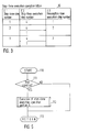
- Fig. 12 is a flowchart for a processing sequence in the process sequence controlling section 4 shown in Fig. 7. The processing sequence for executing the SFC program illustrated in Fig. 9 will now be described with reference to Fig. 12.
- a step number stored in the currently executed step number storage table 32 i.e., the currently executed step number
- the step number C1 stored in the table 32 is read and the step operation program C3 corresponding to that step number is fetched and executed from the step operation program table 33.
- a line on which the executed step number A1 matches the currently executed step number stored in the table 32 is retrieved from the process sequence operation table 31 in order to obtain a next operated step number, and at step 104, the transition condition number A2 on the line where the above step numbers have matched is obtained and the transition condition program D2 corresponding to that number is fetched and executed from the transition condition program table 34.
- step 105 it is checked to see if the transition condition has been enabled. If it has been enabled, the next executed step number is obtained from the next executed step number A3 in the process sequence operation table 31 and stored into the table 32 at step 106, and the processing returns to step 102. If the transition condition has not been enabled at step 105, the processing returns to step 102.
- step S1 in the SFC program shown in Fig. 9 An error occurring at step S1 in the SFC program shown in Fig. 9 will now be described. If an error has taken place at step S1, neither of the transition conditions T1 or T2 is enabled, and the operation stops progressing. To avoid this, error processing is provided in the process sequence program itself. That is, as shown in the arm containing the transition condition T7 through the jump J1 in Fig. 9, a clamp error is checked at the transition condition T7, the workpiece A 51 or workpiece B 52 is unclamped and the cause of the fault is eliminated at the step S7. Then it is confirmed at the transition condition T8 that the fault cause has been removed, the execution thereafter jumps to the step S1 at the jump J1, such that the operation, from step 1 and onward, is repeated.
- This error processing is marked ⁇ in the process sequence operation table 31 in Fig. 10.
- the transition condition T1 nor T2 is enabled, that is, when the workpiece has not been set and LS3 58 has been turned ON by the clamper 53, or when either L1 59 or L2 60 has been turned OFF due to an incorrect positioning of either workpiece A 51 or B 52 or when none of the limit switches LS1 56, LS2 57 or LS3 58 has been turned ON even after a pre-determined length of time due, e.g., to a fault of clamper 53 itself, the transition condition of T7 is enabled. Confirmation of the removal of the cause of the fault in the transition condition 78 is made by an operator. The operation restarts with clamping at step 1 after the operator actuates PB 61.
- sequence controlling method of the type specified above is characterized by the following steps:
- Fig. 1 illustrates the arrangement of a sequence controller in a first and second embodiment of the invention.
- Fig. 2 illustrates an example of an SFC program (process sequence operation program) for the sequence controller shown in Fig. 1.
- Fig. 3 illustrates a stop-time execution operation table as an internal table of the sequence controller shown in Fig. 1.
- Fig. 4 illustrates the processing sequence of a process sequence controlling section in the sequence controller shown in Fig. 1.
- Fig. 5 illustrates the processing sequence of a stop signal detector in the sequence controller shown in Fig. 1.
- Fig. 6 illustrates the processing sequence of a stop-time execution operation section in the sequence controller shown in Fig. 1.
- Fig. 7 illustrates the arrangement of a conventional sequence controller.
- Fig. 8 illustrates an example of a controlled object controlled by the sequence controller shown in Fig. 1 or 7.
- Fig. 9 illustrates an example of an SFC program (process sequence operation program) for the sequence controller shown in Fig. 7.
- Fig. 10 illustrates a process sequence operation table and a currently executed step number storage table as internal tables of the sequence controller shown in Fig. 1 or 7.
- Fig. 11 illustrates a step operation program table and a transition condition program table as internal tables of the sequence controller shown in Fig. 1 or 7.
- Fig. 12 illustrates the processing sequence of a process sequence controlling section in the sequence controller shown in Fig. 7.
- Fig. 1 shows the arrangement of a sequence controller exhibiting a first embodiment of the invention and a second embodiment of the invention.
- the numeral 1A indicates a sequence controller
- 3A a table consisting of the conventional table 3 shown in Fig. 7 and an additional stop-time execution operation table 35 which will be described later.
- Reference numeral 5 indicates a stop signal detector acting as an input signal change detecting means for detecting the presence or absence of an input signal change in each process
- 6 a stop-time execution operation section serving as a stop-time operation executer for stopping sequence control on the basis of the input signal change, executing a stop-time operation, and resuming sequence control from the process point where the change was detected, when the input signal change has been restored to the previous state.
- Fig. 2 illustrates the sequence program 3 in the form of an SFC (Sequential Function Chart) employed when the controlled object 2 shown in Fig. 8 is controlled by the sequence controller 1.
- SFC Sequential Function Chart
- the SFC program in Fig. 2 is identical to the one in Fig. 9 with the exception that the transition condition T7, the step S7, the transition condition T8 and the jump J1 are not required.
- Fig. 3 shows the arrangement of the stop-time execution operation table 35 which is part of the table 3A.
- the table 35 comprises a step number E1 at which a stop is expected to occur in the SFC control program for sequence-controlling the controlled object, a step number E2 which is executed when a stop is effected at the step number E1, and a step number E3 which is executed at a resumption time.
- a process sequence operation table 31A in the table 3A does not include the lines marked ⁇ , i.e., the error-time execution steps, in the table 31 shown in Fig. 10.
- the stop-time execution operation table 35 shown in Fig. 3 is provided instead of the lines marked ⁇ .
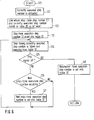
- Fig. 4 is a processing flowchart for a process sequence controlling section 4A
- Fig. 5 a processing flowchart for the stop signal detector 5
- Fig. 6 a processing flowchart for the stop-time execution operation section 6.
- the process sequence controlling section 4A executes the steps indicated in the executed step number A1 in sequence in accordance with the process sequence operation table 31A.
- the stop-time execution operation section 6 is activated and executes a step having the stop-time step number set in the stop-time execution operation table 35.
- the stop signal is then turned off, execution is resumed from the resumption-time execution step number E3 in the table 35.
- the next executed step number is taken from the next executed step number A3 of the process sequence operation table 31A and stored into the table 32, and the processing advances to step 107. If the condition has not been enabled at the step 105, the processing also moves on to the step 107.
- the stop signal detector 5 is called and checked for the presence or absence of the stop signal, i.e., checked for the presence or absence of an error. If the error exists, error processing described below is carried out.
- the execution returns to step 102 and repeats the processing from step 102 onward.
- step 107 The processing at the step 107 will now be described in further detail in accordance with the flowchart illustrated in Fig. 5.
- a signal preassigned as the stop signal among the input signals 7 from the controlled object is checked at step 111 to see if it is on or not (off). If it is not on, the execution goes to step 113 and returns to step 102. If the stop signal is on, the execution advances to step 112 and the stop-time execution operation section 6 is called and performs error processing which will be described later. The execution then progresses to the step 113 and returns to step 102.
- the stop-time execution operation section 6 When the stop-time execution operation section 6 is activated at step 120 in the flowchart illustrated in Fig. 6, the currently executed step number is obtained from the currently executed step number storage table 32 at step 121. Then, at step 122, a line on which the stop-time step number E1 matches the currently executed step number is retrieved in the stop-time execution operation table 35, and at step 123, the step number in the stop-time execution step number E2 of the table 35 is stored into the table 32 as the currently executed step number.
- step 124 the program at the operation step corresponding to the currently executed step number stored in the table 32 is read and executed from the step operation program table 33. Then, at step 125, it is checked to see if the signal preassigned as the stop signal has turned off or not. If it is not off, the execution goes to step 126, where it is judged whether or not the next executed step number exists in the stop-time execution step number E2 in the table 35. If it exists, the next executed step number is stored into the table 32 at step 127. The execution then returns to the step 124 and repeats the processing from the step 124 onward.
- step 128 the execution advances to step 128, where the resumption-time execution step number E3 is checked in the table 35, the corresponding step number is stored into the table 32 as the currently executed step number, and the execution moves on to step 129 and returns to the appropriate processing point.
- a step to be executed during the stop time is selected from the stop-time operation execution table 35. Since the step number to be executed during the stop-time which corresponds to step number 1 (S1) in stop-time operation execution table 35 is step number 4, the program OUT Y11 (workpiece unclamp) which corresponds to step number 4 in the step operation program table 33 is executed. It should be preassigned (i.e., the sequence controller should be programmed) so that the stop signal will be turned OFF when PB 61 for restart is turned ON.
- step S1 step S1
- step S1 step S1
- the SFC program when the SFC program is written as a sequence program for sequence-controlling a controlled object, the program for error processing at the occurrence of a fault or the like is written separately from the sequence program, the stop-time execution operation table 35 is written separately for error processing, the presence or absence of an error is checked on the basis of a change in the predetermined input signal per operation step execution, the sequence control processing is stopped if the error exists, and the operation step having the stop-time execution step number corresponding to the stop-time operation step in the table 35 is executed. After the execution returns to normal on completion of the error processing, the sequence is resumed from the operation step having the resumption-time execution step number.
- the normal and error processing programs do not mingle, and the programs are easy to write, review and revise. Further, since error processing can be carried out by only specifying a step number, the error processing program can be written extremely easily.
- the present invention is not limited to error processing during sequence control processing and a similar effect will be achieved when a manual operation 6 is introduced during an automatic operation.
- various types of special (temporary) manual operations need to be introduced during ordinary automatic operation (after the automatic operation comes to a stop) instead of writing a manual operation program into an automatic operation sequence program, by separately writing and executing a stop-time operation execution table, various temporary manual operation programs need not be written into the ordinary automatic operation program.
- the embodiments of the invention achieve a sequence controller and a sequence control method therefor, the sequence controller being provided with a stop-time operation execution table, which stores stop-time execution step numbers and resumption-time execution step numbers corresponding to step numbers at which a stop is expected to occur in a sequence control program for sequence-controlling a controlled object, so that the execution of the sequence control program is stopped at the occurrence of an error, the stop-time execution step number corresponding to the stop-time step number is read from the stop-time operation execution table, a step having the step number read is executed, and further the resumption-time execution step number is read and the execution is resumed from that step, whereby error processing can be performed by specifying only a step number, the error processing need not be described in the program, and programs can be described easily.
- a stop-time operation execution table which stores stop-time execution step numbers and resumption-time execution step numbers corresponding to step numbers at which a stop is expected to occur in a sequence control program for sequence-controlling
Landscapes
- Physics & Mathematics (AREA)
- General Physics & Mathematics (AREA)
- Engineering & Computer Science (AREA)
- Automation & Control Theory (AREA)
- Programmable Controllers (AREA)
Applications Claiming Priority (2)
| Application Number | Priority Date | Filing Date | Title |
|---|---|---|---|
| JP4003229A JP2848075B2 (ja) | 1992-01-10 | 1992-01-10 | シーケンスコントローラ及びその順序制御方法 |
| JP3229/92 | 1992-01-10 |
Publications (2)
| Publication Number | Publication Date |
|---|---|
| EP0551132A1 EP0551132A1 (en) | 1993-07-14 |
| EP0551132B1 true EP0551132B1 (en) | 1997-04-16 |
Family
ID=11551624
Family Applications (1)
| Application Number | Title | Priority Date | Filing Date |
|---|---|---|---|
| EP93100220A Expired - Lifetime EP0551132B1 (en) | 1992-01-10 | 1993-01-08 | Sequence controller including error correction and method therefor |
Country Status (6)
| Country | Link |
|---|---|
| US (1) | US5485366A (ja) |
| EP (1) | EP0551132B1 (ja) |
| JP (1) | JP2848075B2 (ja) |
| KR (1) | KR960016797B1 (ja) |
| DE (1) | DE69309721T2 (ja) |
| HK (1) | HK1006043A1 (ja) |
Families Citing this family (10)
| Publication number | Priority date | Publication date | Assignee | Title |
|---|---|---|---|---|
| JP3422124B2 (ja) * | 1995-03-30 | 2003-06-30 | マツダ株式会社 | プログラム作成装置 |
| JP3679844B2 (ja) * | 1995-11-09 | 2005-08-03 | ファナック株式会社 | シーケンス・プログラムの実行装置 |
| KR100423742B1 (ko) * | 2000-10-31 | 2004-03-24 | 삼성중공업 주식회사 | 순차기능챠트에 의한 전용 제어 시스템 |
| US20040144378A1 (en) * | 2001-05-15 | 2004-07-29 | Price Raymond R. | Block dressing apparatus and method |
| KR20040035534A (ko) * | 2002-10-22 | 2004-04-29 | 주식회사 커미조아 | 산업용 계측 제어기기의 비정상 상태 제어 방법 |
| JP2004265060A (ja) * | 2003-02-28 | 2004-09-24 | Denso Corp | プログラマブル・ロジック制御装置及び制御方法 |
| US9021299B2 (en) * | 2011-02-18 | 2015-04-28 | Ab Initio Technology Llc | Restarting processes |
| JP2015210751A (ja) * | 2014-04-30 | 2015-11-24 | パナソニック デバイスSunx株式会社 | プログラマブルコントローラ、制御方法及び制御プログラム |
| JP6087478B1 (ja) * | 2016-01-27 | 2017-03-01 | 三菱電機株式会社 | 制御装置及び編集装置 |
| KR102314419B1 (ko) * | 2021-07-27 | 2021-10-19 | (주) 에이블리 | 반도체 테스트 패턴 발생 장치 및 방법 |
Family Cites Families (12)
| Publication number | Priority date | Publication date | Assignee | Title |
|---|---|---|---|---|
| JPS5557956A (en) * | 1978-10-25 | 1980-04-30 | Nissan Motor Co Ltd | Malfunction prevention unit of microcomputer |
| JPS6099545A (ja) * | 1983-11-02 | 1985-06-03 | Mitsubishi Heavy Ind Ltd | 工作機械 |
| US4638227A (en) * | 1984-01-18 | 1987-01-20 | Hitachi, Ltd. | Method and apparatus for recovering normality in moving sequence of machinery |
| JPS60205639A (ja) * | 1984-03-29 | 1985-10-17 | Nec Corp | アドレスストツプ回路 |
| CA1305238C (en) * | 1985-07-19 | 1992-07-14 | Rodger T. Lovrenich | Control system with diagnostic logic |
| JPH07117863B2 (ja) * | 1987-06-26 | 1995-12-18 | 株式会社日立製作所 | オンラインシステムの再立上げ方式 |
| JPH06105401B2 (ja) * | 1988-02-08 | 1994-12-21 | 日東電工株式会社 | 自動ワークハンドリング装置における多重エラー処理装置 |
| JPH02178809A (ja) * | 1988-12-29 | 1990-07-11 | Isao Shoda | 工作機のnc制御装置 |
| GB2233128B (en) * | 1989-05-01 | 1993-12-01 | Honda Motor Co Ltd | Method of and apparatus for generating control program |
| EP0416512B1 (en) * | 1989-09-04 | 1995-12-20 | Omron Corporation | A programmable monitor system and method |
| JP2526686B2 (ja) * | 1989-12-26 | 1996-08-21 | 三菱電機株式会社 | プログラマブルコントロ―ラの制御プログラムにおけるプログラム内容の修正方法 |
| JP2526709B2 (ja) * | 1990-05-08 | 1996-08-21 | 三菱電機株式会社 | プログラマブルコントロ―ラおよびプログラマブルコントロ―ラのsfcプログラム実行方法 |
-
1992
- 1992-01-10 JP JP4003229A patent/JP2848075B2/ja not_active Expired - Fee Related
-
1993
- 1993-01-07 KR KR1019930000127A patent/KR960016797B1/ko not_active IP Right Cessation
- 1993-01-08 DE DE69309721T patent/DE69309721T2/de not_active Expired - Fee Related
- 1993-01-08 US US08/002,027 patent/US5485366A/en not_active Expired - Fee Related
- 1993-01-08 EP EP93100220A patent/EP0551132B1/en not_active Expired - Lifetime
-
1998
- 1998-06-11 HK HK98105194A patent/HK1006043A1/xx not_active IP Right Cessation
Also Published As
| Publication number | Publication date |
|---|---|
| KR930016844A (ko) | 1993-08-30 |
| JP2848075B2 (ja) | 1999-01-20 |
| HK1006043A1 (en) | 1999-02-05 |
| DE69309721D1 (de) | 1997-05-22 |
| JPH05189016A (ja) | 1993-07-30 |
| US5485366A (en) | 1996-01-16 |
| EP0551132A1 (en) | 1993-07-14 |
| DE69309721T2 (de) | 1997-11-27 |
| KR960016797B1 (ko) | 1996-12-21 |
Similar Documents
| Publication | Publication Date | Title |
|---|---|---|
| US4288849A (en) | Machine tool control systems | |
| EP0551132B1 (en) | Sequence controller including error correction and method therefor | |
| EP0171435B1 (en) | Numerical control method | |
| US4751652A (en) | Numerical control drilling restart control system | |
| US7110851B2 (en) | Numerically controlled device | |
| JPH01146642A (ja) | 切削工具の停止制御装置 | |
| US4992928A (en) | Multiple error processor in automatic work handling apparatus | |
| JP2002091521A (ja) | 制御装置及び制御方法 | |
| JP2672595B2 (ja) | 工具入替え方法 | |
| JPH0651258B2 (ja) | 自動復帰機能を有するnc制御装置 | |
| JP3246360B2 (ja) | 自動加工装置および自動加工方法 | |
| JPH10113836A (ja) | Nc工作機械の使用工具チェック方法および装置 | |
| EP0915403A1 (en) | Numerical control unit | |
| JPS6119380B2 (ja) | ||
| JPH07152416A (ja) | プログラム再開機能を備えた数値制御装置 | |
| KR0176554B1 (ko) | 위치결정유니트를 이용한 자동화설비 시스템 제어방법 | |
| KR100521857B1 (ko) | 공작기계의 무인 가공 제어방법 | |
| JPH1133878A (ja) | Nc工作機械の加工スケジュール制御方法およびnc装置ならびにnc工作機械の加工スケジュール制御プログラムを記録した記録媒体 | |
| KR20010066502A (ko) | 파레트 매거진 번호 이상 검출 장치 및 방법 | |
| KR830002110B1 (ko) | 수치제어 공작 기계의 시이퀀스 제어방식 | |
| JPS63288684A (ja) | ワ−ク搬送用ロボットにおけるクランプミスの自動補正手段 | |
| JPH0329541B2 (ja) | ||
| JPH0623652A (ja) | ワークオフセット値設定装置 | |
| JPH11191011A (ja) | ロボット制御装置及びその制御方法 | |
| JPS61256408A (ja) | Dncシステム |
Legal Events
| Date | Code | Title | Description |
|---|---|---|---|
| PUAI | Public reference made under article 153(3) epc to a published international application that has entered the european phase |
Free format text: ORIGINAL CODE: 0009012 |
|
| AK | Designated contracting states |
Kind code of ref document: A1 Designated state(s): DE GB |
|
| 17P | Request for examination filed |
Effective date: 19930702 |
|
| 17Q | First examination report despatched |
Effective date: 19950307 |
|
| GRAG | Despatch of communication of intention to grant |
Free format text: ORIGINAL CODE: EPIDOS AGRA |
|
| GRAH | Despatch of communication of intention to grant a patent |
Free format text: ORIGINAL CODE: EPIDOS IGRA |
|
| GRAH | Despatch of communication of intention to grant a patent |
Free format text: ORIGINAL CODE: EPIDOS IGRA |
|
| GRAA | (expected) grant |
Free format text: ORIGINAL CODE: 0009210 |
|
| AK | Designated contracting states |
Kind code of ref document: B1 Designated state(s): DE GB |
|
| REF | Corresponds to: |
Ref document number: 69309721 Country of ref document: DE Date of ref document: 19970522 |
|
| REG | Reference to a national code |
Ref country code: GB Ref legal event code: 727 |
|
| REG | Reference to a national code |
Ref country code: GB Ref legal event code: 727A |
|
| PLBE | No opposition filed within time limit |
Free format text: ORIGINAL CODE: 0009261 |
|
| STAA | Information on the status of an ep patent application or granted ep patent |
Free format text: STATUS: NO OPPOSITION FILED WITHIN TIME LIMIT |
|
| REG | Reference to a national code |
Ref country code: GB Ref legal event code: 727B |
|
| REG | Reference to a national code |
Ref country code: GB Ref legal event code: SP |
|
| 26N | No opposition filed | ||
| PGFP | Annual fee paid to national office [announced via postgrant information from national office to epo] |
Ref country code: DE Payment date: 19991231 Year of fee payment: 8 |
|
| PGFP | Annual fee paid to national office [announced via postgrant information from national office to epo] |
Ref country code: GB Payment date: 20000105 Year of fee payment: 8 |
|
| PG25 | Lapsed in a contracting state [announced via postgrant information from national office to epo] |
Ref country code: GB Free format text: LAPSE BECAUSE OF NON-PAYMENT OF DUE FEES Effective date: 20010108 |
|
| GBPC | Gb: european patent ceased through non-payment of renewal fee |
Effective date: 20010108 |
|
| PG25 | Lapsed in a contracting state [announced via postgrant information from national office to epo] |
Ref country code: DE Free format text: LAPSE BECAUSE OF NON-PAYMENT OF DUE FEES Effective date: 20011101 |