EP0547751A2 - Débimètre électromagnétique - Google Patents
Débimètre électromagnétique Download PDFInfo
- Publication number
- EP0547751A2 EP0547751A2 EP92309900A EP92309900A EP0547751A2 EP 0547751 A2 EP0547751 A2 EP 0547751A2 EP 92309900 A EP92309900 A EP 92309900A EP 92309900 A EP92309900 A EP 92309900A EP 0547751 A2 EP0547751 A2 EP 0547751A2
- Authority
- EP
- European Patent Office
- Prior art keywords
- relationship
- measured
- fluid
- conduit
- flow
- Prior art date
- Legal status (The legal status is an assumption and is not a legal conclusion. Google has not performed a legal analysis and makes no representation as to the accuracy of the status listed.)
- Granted
Links
Images


Classifications
-
- G—PHYSICS
- G01—MEASURING; TESTING
- G01F—MEASURING VOLUME, VOLUME FLOW, MASS FLOW OR LIQUID LEVEL; METERING BY VOLUME
- G01F1/00—Measuring the volume flow or mass flow of fluid or fluent solid material wherein the fluid passes through a meter in a continuous flow
- G01F1/002—Measuring the volume flow or mass flow of fluid or fluent solid material wherein the fluid passes through a meter in a continuous flow wherein the flow is in an open channel
-
- G—PHYSICS
- G01—MEASURING; TESTING
- G01F—MEASURING VOLUME, VOLUME FLOW, MASS FLOW OR LIQUID LEVEL; METERING BY VOLUME
- G01F1/00—Measuring the volume flow or mass flow of fluid or fluent solid material wherein the fluid passes through a meter in a continuous flow
- G01F1/56—Measuring the volume flow or mass flow of fluid or fluent solid material wherein the fluid passes through a meter in a continuous flow by using electric or magnetic effects
- G01F1/58—Measuring the volume flow or mass flow of fluid or fluent solid material wherein the fluid passes through a meter in a continuous flow by using electric or magnetic effects by electromagnetic flowmeters
- G01F1/586—Measuring the volume flow or mass flow of fluid or fluent solid material wherein the fluid passes through a meter in a continuous flow by using electric or magnetic effects by electromagnetic flowmeters constructions of coils, magnetic circuits, accessories therefor
-
- G—PHYSICS
- G01—MEASURING; TESTING
- G01F—MEASURING VOLUME, VOLUME FLOW, MASS FLOW OR LIQUID LEVEL; METERING BY VOLUME
- G01F1/00—Measuring the volume flow or mass flow of fluid or fluent solid material wherein the fluid passes through a meter in a continuous flow
- G01F1/56—Measuring the volume flow or mass flow of fluid or fluent solid material wherein the fluid passes through a meter in a continuous flow by using electric or magnetic effects
- G01F1/58—Measuring the volume flow or mass flow of fluid or fluent solid material wherein the fluid passes through a meter in a continuous flow by using electric or magnetic effects by electromagnetic flowmeters
- G01F1/588—Measuring the volume flow or mass flow of fluid or fluent solid material wherein the fluid passes through a meter in a continuous flow by using electric or magnetic effects by electromagnetic flowmeters combined constructions of electrodes, coils or magnetic circuits, accessories therefor
-
- G—PHYSICS
- G01—MEASURING; TESTING
- G01F—MEASURING VOLUME, VOLUME FLOW, MASS FLOW OR LIQUID LEVEL; METERING BY VOLUME
- G01F1/00—Measuring the volume flow or mass flow of fluid or fluent solid material wherein the fluid passes through a meter in a continuous flow
- G01F1/56—Measuring the volume flow or mass flow of fluid or fluent solid material wherein the fluid passes through a meter in a continuous flow by using electric or magnetic effects
- G01F1/58—Measuring the volume flow or mass flow of fluid or fluent solid material wherein the fluid passes through a meter in a continuous flow by using electric or magnetic effects by electromagnetic flowmeters
- G01F1/60—Circuits therefor
-
- G—PHYSICS
- G01—MEASURING; TESTING
- G01F—MEASURING VOLUME, VOLUME FLOW, MASS FLOW OR LIQUID LEVEL; METERING BY VOLUME
- G01F25/00—Testing or calibration of apparatus for measuring volume, volume flow or liquid level or for metering by volume
- G01F25/10—Testing or calibration of apparatus for measuring volume, volume flow or liquid level or for metering by volume of flowmeters
- G01F25/13—Testing or calibration of apparatus for measuring volume, volume flow or liquid level or for metering by volume of flowmeters using a reference counter
Definitions
- the present invention relates to electromagnetic flowmeters and more particularly to an electromagnetic flowmeter which measures the flow of a fluid which flows through a conduit, whether or not the conduit is full with the fluid.
- an electromagnetic flowmeter which measures the flow of a fluid which flows through a conduit in a state where the conduit is full with a fluid.
- Murase and others have proposed an electromagnetic flowmeter which is composed of an energizing coil disposed above a conduit, a pair of electrodes disposed below of the conduit and circuitry which controls those coils (JP-A-01-29224). According to this flowmeter, even if the conduit is not full with a test fluid, the measurement of the flow of the fluid is possible theoretically.
- Watanabe and others have proposed a detector which detects whether a conduit is full with a flowing fluid or not, the detector comprising a pair of coils each disposed above and below a conduit, a unit for selecting and driving one of these coils, a pair of electrodes disposed on the corresponding sides of the conduit, and circuitry which selects energization of a coil, as disclosed in JP-A-59-2302115.
- the electromagnetic flowmeter of this invention is composed of a pair of upper and lower energizing coils disposed above and below a conduit, a sensor which provides an output corresponding to the state of a test fluid which flows through the conduit when the respective coils are energized, and a control circuit which controls the energization of the respective coils.
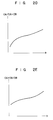
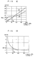
- Fig. 1 shows the relationship between a flow Q and the output from the sensor disposed in a conduit having a known gradient and a known diameter or a cross-sectional configuration.
- a curve OA in Fig. 1 represents a relationship (first relationship) obtained when the upper coil is energized while a curve OB represents a relationship (second relationship) obtained when the lower coil is energized. Since the gradient and diameter of the conduit is known, the level h of the fluid is uniquely determined for the flow Q.
- the horizontal axis of Fig. 1 is scaled with both flow Q and level h of the fluid. The level is indicated as a percentage of the level to the diameter D of the conduit.
- Fig. 2 represents a relationship (fourth relationship) between a ratio K(h) (third relationship) of curve OB to curve OA and level h.
- a fluid which flows through a flow sensor of an electromagnetic flowmeter having a pair of electrodes 2 disposed across a circular cross-sectional conduit 1 and a saddle-shaped energizing coil 3A disposed on top of conduit 1 is maintained at a level (0.5D) of half the diameter (inner diameter) D of the conduit 1, it is considered that the flowmeter is the same in measuring conditions as a full-fluid flowmeter with a flow path having a cross-section equal to the lower half of the conduit. Therefore, the output OA from the electromagnetic flowmeter is represented by a straight line proportional to the flow, as shown in Fig. 4.
- the gradient k of this line represents the sensitivity of a virtual full-fluid electromagnetic flowmeter.
- the sensitivity is normally constant in the full-fluid electromagnetic flowmeter, so that the sensitivity of the virtual full-fluid flowmeter is also constant as long as the level h is maintained constant. That is, the sensitivity k is a function of level h.
- a magnetic flux density distribution BA due to upper coil 3A is considered to be constant.
- its output is represented by the product of a magnetic flux density, the flow and the distance between the electrodes. Therefore, also in this case, the density k can be expressed by a function k(BA, h) where BA is a magnetic flux density distribution, and h is the level of the fluid when the conduit cross-section configuration is strictly constant.
- OA k(BA, h) Q (1)
- OB k'(BB, h) Q (2) .
- Magnetic flux density distributions BA and BB are fixed density distributions obtained by energizing coils 3A and 3B, so that k'(BB, h)/k(BA, h) can be handled as a function of only level h.
- OA/OB Fig. 2B
- OB/(OA + OB) Fig. 2C
- OA/(OA + OB) Fig. 2D
- OA + OB/OB(Fig. 2E) Fig. 2F
- OA + OB/OA(Fig. 2F) may be similarly used to determine the level of the fluid because they are each a function of level h alone.
- Fig. 5 shows the relationship between each of gradients of conduits and flow Q at a respective one of various levels. If conduits whose flows are to be measured have the same cross-sectional configuration and their gradients are known, the flows of fluids flowing through the conduits are obtained by specifying the levels of the fluids using the above method.
- the flow is obtained by storing data on the relationships of Fig. 5 in a memory of a computer system and inputting a level and a gradient into the system.
- the level takes three values, for example, of 0.2D, 0.5D and 0.9D.
- the measurement is equal to measurement using full-fluid electromagnetic flowmeters having different cross-sectional configurations such as those shown in Figs. 6A, 6B and 6C.
- a flow Q in a reference conduit whose gradient is already known, used to obtain the relationship of Figs. 1 and 2A at the level h' is obtained because the flow and level are in a one-two-one relationship in the reference conduit.
- An output OA(h') in the reference conduit at level h' or at flow Q is determined from the curve OA of Fig. 1.
- the curve OA of Fig. 1 (first relationship) and the relationship in Fig. 2A (fourth relationship) are stored as data in the memory of the computer system. While the relationship for the curve OA is used in the above example when the sensitivity k(h') is calculated, the relationship for the curve OB or the curve OA + OB may be used.
- the level may be used in any method.
- a dam expression known conventionally may be used.
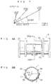
- reference numeral 1 denotes a measured circular cross-sectional conduit through which a measured fluid flows; 2, a pair of electrodes provided at positions symmetrical around a vertical line passing through an axis of the conduit 1; 3A, 3B, a first and a second energizing coil which generate different magnetic flux density distributions BA and BB at different intervals of time; and 4, a flow sensor having such structure.
- the electrodes 2 are asymmetrical around a horizontal axis of the conduit 1.
- the central angle ⁇ (V) subtending the electrode portions positioned above the horizontal axis is preferably 30-40 degrees.
- An energizing circuit 5 alternately energizes a first and second energizing coils 3A and 3B in accordance with a signal from a timing circuit 6.
- Reference numeral 7 denotes an amplifier which amplifies and outputs a voltage induced across the electrodes 2; S1, a changeover switch which is switched in accordance with a signal from the timing circuit 6 synchronously with the timing signal of energization of the energizing coils 3A and 3B.
- Reference characters 8A and 8B denote a first and a second sample and hold circuit which performs an sample and hold operation by receiving a signal through the contacts a and b; 9, CPU; 10, an A/D converter which converts an analog signal from each of sample and hold circuits 8A, 8B to a digital signal; 11, a correction circuit which stores a program for the above correction; and 12, an output terminal which outputs a flow signal Q' as the result of the correction.
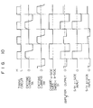
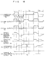
- Fig. 10 is a timing chart for the electromagnetic flowmeter of Fig. 9 which shows a signal from the timing circuit 6, energizing currents flowing through the first and second energizing coils 3A and 3B, the operation of the changeover switch S1, the output from amplifier 7, and inputs to sample and hold circuits 8A and 8B.
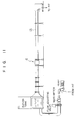
- Fig. 11 shows the overall device used for an experiment to examine the accuracy of the inventive measuring method and having the flow sensor 4 of Figs. 8 and 9 attached to a vinyl chloride tube 13 having an inner diameter of 200mm and a length of about 8m.
- the gradient of this tube is fixed at 2/1000.
- the relationship between the output OA of the electromagnetic flowmeter and the actual flow Q measured using the first energizing coil 3A is shown by a curve OA in Fig. 12.
- the result of the measurement obtained by using the second energizing coil 3B at the same gradient of the conduit used is shown by a curve OB.
- Fig. 13 shows a ratio OB/OA obtained from both data OA and OB of Fig. 12. While in Fig. 13 the ratio OB/OA is a minimum constant value when the flow Q is substantially larger than 100 [m3/h], which shows a full state of the conduit. It will be seen in Fig. 12 from the fact that in the range where the flow Q is substantially larger than 100[m3/h] the curves OA and OB have straight line segments which will pass through the origin of the coordinates that the flowmeter operates as a regular so-called full-fluid type electromagnetic flowmeter.
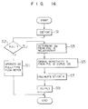
- CPU 9 stores in registers (not shown) data on the outputs OA' and OB' from sensor electrodes 2 delivered from sample and hold circuits 8A, 8B and obtained when the upper and lower coils 3A and 3B, respectively, are energized.
- a correction calculating circuit 11 reads out the respective outputs OB' and OA' from the corresponding registers and calculates a ratio OB'/OA'.
- the circuit 11 determines whether the conduit is full with a flowing fluid or not. When OB'/OA' is equal to the value T of the straight line of Fig. 13, the circuit determines that the conduit is full with the fluid and control passes to step 11. If OB'/OA' is larger than T, the circuit 11 determines that the conduit is not full, and control passes to step 3, where the circuit 11 determines a flow Q ⁇ flowing through the reference conduit in accordance with the relationship of Fig. 13 stored in the memory 100.
- the calculating circuit 11 again reads output OA' from the register and multiplies the output OA' by the sensitivity k obtained at the preceding step to determine a measured flow Q', and then outputs it (step 9).
- the electromagnetic flowmeter of this embodiment operates as a full-fluid type one (step 11). More specifically, it multiplies output OA' by the sensitivity k present when the conduit is full or at an level of 1.0D. The sensitivity is obtained beforehand.
- the device difference implies the difference in output value between a standard flowmeter and the electromagnetic flowmeter of the present embodiment.
- Fig. 17 shows a second embodiment of the electromagnetic flowmeter of the present invention. It additionally has modified details of the energizing circuit 5, changeover switch S1, first and second sample and hold circuits 8A, 8B and CPU 9 of Fig. 9.
- the energizing circuit 5 is provided with two energizing units which energize the energizing coils 3A and 3B alternately in accordance with the signal from the timing circuit 6.
- the changeover switch S1 is composed of changeover switches Swa and Swb.
- Swa When one changeover switch, for example, Swa, supplies the output signal from amplifier 7 to the first sample and hold circuit 8A, the other changeover switch Swb grounds the input b to the second sample and hold circuit 8B.
- the first and second sample and hold circuit 8A and 8B have the same structural details and are each composed of an offset voltage removal unit 8a, absolute value unit 8b, integrator 8c, sample and hold circuit 8d and an offset and amplification degree adjusting unit 8e.
- Reference characters A and B denote the corresponding output terminals for the first and second sample and hold circuits 8A and 8B.
- CPU 9 is composed of an A/D converter 10, microprocessor unit 11c which is provided with built-in RAM 11a and ROM 11b, D/A converter 11d and V/I converter 11e.
- the built-in ROM 11c stores a correction program 14 and correction reference data 15, to be described later in more detail.
- CPU 9 outputs an analog flow signal of 4-20mA at its output 12.
- the two energizing units of the energizing circuit 5 operate alternately to supply energizing currents alternately to the energizing coils 3A and 3B.
- An electromotive force generated across the electrodes 2 is delivered to the amplifier 7, whose output is supplied alternately to the first and second sample and hold circuits 8A, 8B through the changeover switches Swa and Swb depending on which of the energizing coils 3A, 3B is energized.
- the output V6 is output as an output voltage V7 to the output terminal A through the offset and amplification degree adjusting unit 8e.
- the output voltage V7 corresponds to the output OA or OA'.
- the output voltage supplied to the output terminal B of the second sample and hold circuit 8B corresponds to the output OA or OB'.
- CPU 9 operates as follows. CPU 9 operates in timing independently of the sample and hold circuits 8A and 8B.
- Fig. 19 shows the flow of the operation of CPU 9 and repeats the processing at steps (1)-(4) as shown at intervals of time tr.
- the voltage outputs at the output terminals A and B of the first and second sample and hold circuits 8A, 8B are updated at intervals of time (t1 + t2) as will be obvious from the timing chart of Fig. 18, so that decreasing the period tr compared to the interval of time (t1 + t2) implies taking the same output more than once, which is an ineffective operation.
- Procedures (1) The outputs at the output terminals A and B of the sample and hold circuits 8A, 8B are A/D sampled by the A/D converter 10. It is assumed at this time that the unknown flow Q' is already measured and that the outputs at the output terminals A and B correspond to the outputs O'A and O'B, respectively.
- Procedure (2) for moving average processing Noise is contained in outputs O'A and O'B.
- complicated correction such as taking an output ratio O'B/O'A is made, so that it is preferable to eliminate noise to some extent and then to resort to the correction procedures.
- a moving average is taken, in which the last n A/D sampled data values obtained so far are partially updated at each sampling and stored in a memory and the arithmetic mean value of those data is used in the subsequent correction.
- Procedures (3) for correction The procedures for correction described in detail in the explanation of the correction will be described.
- the inventive electromagnetic flowmeter is attached to a conduit with a given gradient.
- a reference meter By controlling the flow using a reference meter while measuring outputs OA, OB, data on Table 1 below is obtained.
- Figs. 1 and 2A are required to be reproduced approximately from data on the coordinates by linear interpolation (which includes connection of dots by straight line segments).
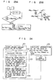
- Fig. 23A shows one example of an algorithm which performs the correction procedures by linear interpolation.
- Fig. 23 is a flowchart indicative of an algorithm which obtains a flow Q ⁇ from the output ratio O'B/O'A. In this case, it assumed that reference data at several points are already recorded on the built-in ROM 11b.
- the basic flow of the proper correction procedures are steps 101-105 of Fig. 24, the details of which will be obvious from the above description.
- the correction program 14 for this processing is beforehand stored in the built-in ROM 11b of Fig. 17.
- the RAM 11a and ROM 11b are not necessarily required to be built in the microprocessor 11c, but may be provided outside the microprocessor 11c.
- Procedure (4) The result of the correction is converted by the D/A converter 11d to an analog value, which is then converted by a V/I converter 11e to an analog current output of 4-20mA.
- different magnetic flux density distributions BA and BB were generated by using a flowmeter which is substantially the same in function as the known electromagnetic flowmeters and using the two energizing coils selectively.
- the flow in the non-full state was also measured by correction on the basis of the outputs OA and OB which were obtained from the magnetic densities BA and BB.
- the structure of the hardware is not especially complicated compared to the conventional electromagnetic flowmeter.
- direct level measurement is not required, so that the flow measurement is not adversely affected by waves and voids on a surface of the flow of the fluid.
- the inventive flowmeter causes no damage to the conduit.
- the flow can be measured with high accuracy without being adversely affected by a gradient of the conduit. Furthermore, the flow can be measured with high accuracy in the full fluid state like the conventional full-fluid type electromagnetic flowmeter.
Applications Claiming Priority (2)
| Application Number | Priority Date | Filing Date | Title |
|---|---|---|---|
| JP335050/91 | 1991-12-18 | ||
| JP3335050A JP2974478B2 (ja) | 1991-01-22 | 1991-12-18 | 非満水状態での流量計測方法と、この方法に使う流量検出器及び電磁流量計 |
Publications (3)
| Publication Number | Publication Date |
|---|---|
| EP0547751A2 true EP0547751A2 (fr) | 1993-06-23 |
| EP0547751A3 EP0547751A3 (fr) | 1994-04-20 |
| EP0547751B1 EP0547751B1 (fr) | 1997-08-13 |
Family
ID=18284187
Family Applications (1)
| Application Number | Title | Priority Date | Filing Date |
|---|---|---|---|
| EP92309900A Expired - Lifetime EP0547751B1 (fr) | 1991-12-18 | 1992-10-29 | Débimètre électromagnétique |
Country Status (2)
| Country | Link |
|---|---|
| EP (1) | EP0547751B1 (fr) |
| DE (1) | DE69221595T2 (fr) |
Cited By (11)
| Publication number | Priority date | Publication date | Assignee | Title |
|---|---|---|---|---|
| EP0638785A2 (fr) * | 1993-08-11 | 1995-02-15 | Fischer & Porter GmbH | Dispositif pour la mesure de l'écoulement d'un liquide à travers un tuyeau de mesure |
| EP0641998A2 (fr) * | 1993-09-07 | 1995-03-08 | Fischer & Porter GmbH | Dispositif pour la mesure de l'écoulement d'un liquide à travers d'un tube de mesure |
| EP0641999A1 (fr) * | 1993-09-07 | 1995-03-08 | Fischer & Porter GmbH | Dispositif de mesure du débit d'un liquide à travers d'un conduit de mesure |
| DE4437275A1 (de) * | 1994-10-18 | 1996-04-25 | Fischer & Porter Gmbh | Verfahren zur Kompensation von Fehlern in Meßwertsignalen magnetisch-induktiver Durchflußmesser |
| DE19531124A1 (de) * | 1995-08-24 | 1997-02-27 | Krohne Messtechnik Kg | Verfahren zur Bestimmung des Phasenanteils eines Mediums in offenen und geschlossenen Leitungen |
| DE19615140A1 (de) * | 1996-04-17 | 1997-10-23 | Krohne Messtechnik Kg | Vorrichtung zur Bestimmung des Phasenanteils eines leitfähigen Mediums in einer Leitung |
| US6092428A (en) * | 1996-04-17 | 2000-07-25 | Krohne Messtechnik Gmbh & Co. Kg | Device for determining the phase component of a conductive medium in a duct |
| CN103954306A (zh) * | 2014-04-15 | 2014-07-30 | 无锡市星翼仪表科技有限公司 | 小型化高精度微量程传感器及流量计 |
| WO2018127735A1 (fr) * | 2017-01-03 | 2018-07-12 | Abb Schweiz Ag | Débitmètre électromagnétique et procédé de fonctionnement du débitmètre électromagnétique pour détecter un écoulement de fluides multiphases |
| CN108955838A (zh) * | 2018-08-17 | 2018-12-07 | 浙江清环智慧科技有限公司 | 非满管流量校准装置 |
| CN112985528A (zh) * | 2021-02-26 | 2021-06-18 | 上海市计量测试技术研究院 | 一种封闭管道内流量不稳定液体测量装置及其测量方法 |
Citations (9)
| Publication number | Priority date | Publication date | Assignee | Title |
|---|---|---|---|---|
| FR2068824A1 (fr) * | 1969-12-18 | 1971-09-03 | Eckardt Ag J | |
| DE2063792A1 (de) * | 1970-12-24 | 1972-07-06 | Eckardt Ag J | Magnetische Abflußmeßeinrichtung |
| US3991612A (en) * | 1975-10-14 | 1976-11-16 | Fischer & Porter Co. | Electromagnetic flowmeter usable in less-than full fluid lines |
| DE2856240A1 (de) * | 1978-12-27 | 1980-07-03 | Krohne Fa Ludwig | Verfahren zur induktiven durchflussmessung von fluessigkeiten in teilgefuellten rohrleitungen oder offenen kanaelen sowie durchflussmesser zur durchfuehrung des verfahrens |
| JPS59230115A (ja) * | 1983-06-11 | 1984-12-24 | Yamatake Honeywell Co Ltd | 電磁流量計 |
| JPH01292214A (ja) * | 1988-05-19 | 1989-11-24 | Aichi Tokei Denki Co Ltd | 電磁流量計 |
| DE9103046U1 (fr) * | 1990-04-09 | 1991-06-13 | Fischer & Porter Gmbh, 3400 Goettingen, De | |
| EP0555493A1 (fr) * | 1991-09-03 | 1993-08-18 | Aichi Tokei Denki Co., Ltd. | Debimetre electromagnetique pour canalisation d'eau a moitie pleine |
| EP0557529A1 (fr) * | 1991-09-03 | 1993-09-01 | Aichi Tokei Denki Co., Ltd. | Debitmetre electromagnetique pour conduites d'eau partiellement remplies |
-
1992
- 1992-10-29 DE DE69221595T patent/DE69221595T2/de not_active Expired - Lifetime
- 1992-10-29 EP EP92309900A patent/EP0547751B1/fr not_active Expired - Lifetime
Patent Citations (9)
| Publication number | Priority date | Publication date | Assignee | Title |
|---|---|---|---|---|
| FR2068824A1 (fr) * | 1969-12-18 | 1971-09-03 | Eckardt Ag J | |
| DE2063792A1 (de) * | 1970-12-24 | 1972-07-06 | Eckardt Ag J | Magnetische Abflußmeßeinrichtung |
| US3991612A (en) * | 1975-10-14 | 1976-11-16 | Fischer & Porter Co. | Electromagnetic flowmeter usable in less-than full fluid lines |
| DE2856240A1 (de) * | 1978-12-27 | 1980-07-03 | Krohne Fa Ludwig | Verfahren zur induktiven durchflussmessung von fluessigkeiten in teilgefuellten rohrleitungen oder offenen kanaelen sowie durchflussmesser zur durchfuehrung des verfahrens |
| JPS59230115A (ja) * | 1983-06-11 | 1984-12-24 | Yamatake Honeywell Co Ltd | 電磁流量計 |
| JPH01292214A (ja) * | 1988-05-19 | 1989-11-24 | Aichi Tokei Denki Co Ltd | 電磁流量計 |
| DE9103046U1 (fr) * | 1990-04-09 | 1991-06-13 | Fischer & Porter Gmbh, 3400 Goettingen, De | |
| EP0555493A1 (fr) * | 1991-09-03 | 1993-08-18 | Aichi Tokei Denki Co., Ltd. | Debimetre electromagnetique pour canalisation d'eau a moitie pleine |
| EP0557529A1 (fr) * | 1991-09-03 | 1993-09-01 | Aichi Tokei Denki Co., Ltd. | Debitmetre electromagnetique pour conduites d'eau partiellement remplies |
Non-Patent Citations (2)
| Title |
|---|
| PATENT ABSTRACTS OF JAPAN vol. 14, no. 76 (P-1005) 13 February 1990 & JP-A-1 292 214 (AICHI TOKEI) * |
| PATENT ABSTRACTS OF JAPAN vol. 9, no. 109 (P-355)14 May 1985 & JP-A-59 230 115 (YAMATAKE HONEYWELL) * |
Cited By (18)
| Publication number | Priority date | Publication date | Assignee | Title |
|---|---|---|---|---|
| EP0638785A3 (fr) * | 1993-08-11 | 1995-11-22 | Fischer & Porter Gmbh | Dispositif pour la mesure de l'écoulement d'un liquide à travers un tuyeau de mesure. |
| EP0638785A2 (fr) * | 1993-08-11 | 1995-02-15 | Fischer & Porter GmbH | Dispositif pour la mesure de l'écoulement d'un liquide à travers un tuyeau de mesure |
| EP0641998A2 (fr) * | 1993-09-07 | 1995-03-08 | Fischer & Porter GmbH | Dispositif pour la mesure de l'écoulement d'un liquide à travers d'un tube de mesure |
| EP0641999A1 (fr) * | 1993-09-07 | 1995-03-08 | Fischer & Porter GmbH | Dispositif de mesure du débit d'un liquide à travers d'un conduit de mesure |
| EP0641998A3 (fr) * | 1993-09-07 | 1995-11-22 | Fischer & Porter Gmbh | Dispositif pour la mesure de l'écoulement d'un liquide à travers d'un tube de mesure. |
| US5493914A (en) * | 1993-09-07 | 1996-02-27 | Fischer & Porter Gmbh | Device for measuring the flow of a fluid flowing through a measuring pipe |
| DE4437275A1 (de) * | 1994-10-18 | 1996-04-25 | Fischer & Porter Gmbh | Verfahren zur Kompensation von Fehlern in Meßwertsignalen magnetisch-induktiver Durchflußmesser |
| US5719340A (en) * | 1995-08-24 | 1998-02-17 | Krohne Ag | Process for determining the phase portion of a fluid medium in open and closed pipes |
| DE19531124A1 (de) * | 1995-08-24 | 1997-02-27 | Krohne Messtechnik Kg | Verfahren zur Bestimmung des Phasenanteils eines Mediums in offenen und geschlossenen Leitungen |
| DE19615140A1 (de) * | 1996-04-17 | 1997-10-23 | Krohne Messtechnik Kg | Vorrichtung zur Bestimmung des Phasenanteils eines leitfähigen Mediums in einer Leitung |
| DE19615140C2 (de) * | 1996-04-17 | 1999-12-16 | Krohne Messtechnik Kg | Magnetisch - induktives Durchflußmeßgerät |
| US6092428A (en) * | 1996-04-17 | 2000-07-25 | Krohne Messtechnik Gmbh & Co. Kg | Device for determining the phase component of a conductive medium in a duct |
| DE19655107C2 (de) * | 1996-04-17 | 2002-11-14 | Krohne Messtechnik Kg | Magnetisch-induktives Durchflußmeßgerät |
| CN103954306A (zh) * | 2014-04-15 | 2014-07-30 | 无锡市星翼仪表科技有限公司 | 小型化高精度微量程传感器及流量计 |
| CN103954306B (zh) * | 2014-04-15 | 2016-03-23 | 无锡市星翼仪表科技有限公司 | 小型化高精度微量程传感器及流量计 |
| WO2018127735A1 (fr) * | 2017-01-03 | 2018-07-12 | Abb Schweiz Ag | Débitmètre électromagnétique et procédé de fonctionnement du débitmètre électromagnétique pour détecter un écoulement de fluides multiphases |
| CN108955838A (zh) * | 2018-08-17 | 2018-12-07 | 浙江清环智慧科技有限公司 | 非满管流量校准装置 |
| CN112985528A (zh) * | 2021-02-26 | 2021-06-18 | 上海市计量测试技术研究院 | 一种封闭管道内流量不稳定液体测量装置及其测量方法 |
Also Published As
| Publication number | Publication date |
|---|---|
| DE69221595D1 (de) | 1997-09-18 |
| DE69221595T2 (de) | 1997-12-11 |
| EP0547751B1 (fr) | 1997-08-13 |
| EP0547751A3 (fr) | 1994-04-20 |
Similar Documents
| Publication | Publication Date | Title |
|---|---|---|
| EP0557529B1 (fr) | Debitmetre electromagnetique pour conduites d'eau partiellement remplies | |
| KR100216646B1 (ko) | 전자유량계 | |
| EP0547751A2 (fr) | Débimètre électromagnétique | |
| US5443552A (en) | Electromagnetic flowmeter and method for electromagnetically measuring flow rate | |
| EP0559350A1 (fr) | Dispositif et procédé pour la détection d'un état pas-plein | |
| US6611770B1 (en) | Liquid conduction indication in a magnetic flowmeter | |
| US5625155A (en) | Electromagnetic flowmeter | |
| US5524493A (en) | Electromagnetic flowmeter | |
| JP2974478B2 (ja) | 非満水状態での流量計測方法と、この方法に使う流量検出器及び電磁流量計 | |
| EP0555493B1 (fr) | Debimetre electromagnetique pour canalisation d'eau a moitie pleine | |
| JP3018311B2 (ja) | 電磁流量計 | |
| JP4180702B2 (ja) | 非満水電磁流量計 | |
| JP3334995B2 (ja) | 電磁流量計 | |
| JPH07324959A (ja) | 電磁流量計 | |
| JPH0552619A (ja) | 電磁流量計 | |
| JP3133143B2 (ja) | 電磁流量計 | |
| JP2945476B2 (ja) | 非満水用電磁流量計 | |
| JP3244341B2 (ja) | 電磁流量計 | |
| JPH0466818A (ja) | 電磁流量計 | |
| JP2945475B2 (ja) | 非満水用電磁流量計 | |
| JPH10221135A (ja) | 電磁流量計 | |
| JPH06258113A (ja) | 電磁流量計 | |
| JP3062915B2 (ja) | 2線式電磁流量計 | |
| JPH07209049A (ja) | 2線式電磁流量計 | |
| JP3015996B2 (ja) | 2線式電磁流量計 |
Legal Events
| Date | Code | Title | Description |
|---|---|---|---|
| PUAI | Public reference made under article 153(3) epc to a published international application that has entered the european phase |
Free format text: ORIGINAL CODE: 0009012 |
|
| AK | Designated contracting states |
Kind code of ref document: A2 Designated state(s): CH DE FR GB LI |
|
| RHK1 | Main classification (correction) |
Ipc: G01F 1/60 |
|
| PUAL | Search report despatched |
Free format text: ORIGINAL CODE: 0009013 |
|
| AK | Designated contracting states |
Kind code of ref document: A3 Designated state(s): CH DE FR GB LI |
|
| 17P | Request for examination filed |
Effective date: 19940905 |
|
| 17Q | First examination report despatched |
Effective date: 19941128 |
|
| GRAG | Despatch of communication of intention to grant |
Free format text: ORIGINAL CODE: EPIDOS AGRA |
|
| GRAH | Despatch of communication of intention to grant a patent |
Free format text: ORIGINAL CODE: EPIDOS IGRA |
|
| GRAH | Despatch of communication of intention to grant a patent |
Free format text: ORIGINAL CODE: EPIDOS IGRA |
|
| GRAA | (expected) grant |
Free format text: ORIGINAL CODE: 0009210 |
|
| AK | Designated contracting states |
Kind code of ref document: B1 Designated state(s): CH DE FR GB LI |
|
| REG | Reference to a national code |
Ref country code: CH Ref legal event code: NV Representative=s name: A. BRAUN, BRAUN, HERITIER, ESCHMANN AG PATENTANWAE Ref country code: CH Ref legal event code: EP |
|
| REF | Corresponds to: |
Ref document number: 69221595 Country of ref document: DE Date of ref document: 19970918 |
|
| ET | Fr: translation filed | ||
| PLBE | No opposition filed within time limit |
Free format text: ORIGINAL CODE: 0009261 |
|
| STAA | Information on the status of an ep patent application or granted ep patent |
Free format text: STATUS: NO OPPOSITION FILED WITHIN TIME LIMIT |
|
| 26N | No opposition filed | ||
| REG | Reference to a national code |
Ref country code: GB Ref legal event code: IF02 |
|
| REG | Reference to a national code |
Ref country code: CH Ref legal event code: PFA Owner name: AICHI TOKEI DENKI CO., LTD. Free format text: AICHI TOKEI DENKI CO., LTD.#2-70, CHITOSE 1-CHOME ATSUTA-KU#NAGOYA-SHI AICHI-KEN 456-91 (JP) -TRANSFER TO- AICHI TOKEI DENKI CO., LTD.#2-70, CHITOSE 1-CHOME ATSUTA-KU#NAGOYA-SHI AICHI-KEN 456-91 (JP) |
|
| PGFP | Annual fee paid to national office [announced via postgrant information from national office to epo] |
Ref country code: FR Payment date: 20081029 Year of fee payment: 17 |
|
| REG | Reference to a national code |
Ref country code: FR Ref legal event code: ST Effective date: 20100630 |
|
| PG25 | Lapsed in a contracting state [announced via postgrant information from national office to epo] |
Ref country code: FR Free format text: LAPSE BECAUSE OF NON-PAYMENT OF DUE FEES Effective date: 20091102 |
|
| PGFP | Annual fee paid to national office [announced via postgrant information from national office to epo] |
Ref country code: DE Payment date: 20101019 Year of fee payment: 19 |
|
| PGFP | Annual fee paid to national office [announced via postgrant information from national office to epo] |
Ref country code: GB Payment date: 20101027 Year of fee payment: 19 |
|
| PGFP | Annual fee paid to national office [announced via postgrant information from national office to epo] |
Ref country code: CH Payment date: 20111025 Year of fee payment: 20 |
|
| REG | Reference to a national code |
Ref country code: DE Ref legal event code: R071 Ref document number: 69221595 Country of ref document: DE |
|
| REG | Reference to a national code |
Ref country code: DE Ref legal event code: R071 Ref document number: 69221595 Country of ref document: DE |
|
| REG | Reference to a national code |
Ref country code: CH Ref legal event code: PL |
|
| REG | Reference to a national code |
Ref country code: GB Ref legal event code: PE20 Expiry date: 20121028 |
|
| PG25 | Lapsed in a contracting state [announced via postgrant information from national office to epo] |
Ref country code: GB Free format text: LAPSE BECAUSE OF EXPIRATION OF PROTECTION Effective date: 20121028 |