EP0547232A1 - Vergrösserungs-beobachtungsvorrichtung - Google Patents
Vergrösserungs-beobachtungsvorrichtung Download PDFInfo
- Publication number
- EP0547232A1 EP0547232A1 EP92913998A EP92913998A EP0547232A1 EP 0547232 A1 EP0547232 A1 EP 0547232A1 EP 92913998 A EP92913998 A EP 92913998A EP 92913998 A EP92913998 A EP 92913998A EP 0547232 A1 EP0547232 A1 EP 0547232A1
- Authority
- EP
- European Patent Office
- Prior art keywords
- imaging device
- light
- image pick
- image
- observed
- Prior art date
- Legal status (The legal status is an assumption and is not a legal conclusion. Google has not performed a legal analysis and makes no representation as to the accuracy of the status listed.)
- Granted
Links
Images


Classifications
-
- H—ELECTRICITY
- H04—ELECTRIC COMMUNICATION TECHNIQUE
- H04N—PICTORIAL COMMUNICATION, e.g. TELEVISION
- H04N7/00—Television systems
- H04N7/18—Closed-circuit television [CCTV] systems, i.e. systems in which the video signal is not broadcast
-
- G—PHYSICS
- G06—COMPUTING; CALCULATING OR COUNTING
- G06K—GRAPHICAL DATA READING; PRESENTATION OF DATA; RECORD CARRIERS; HANDLING RECORD CARRIERS
- G06K7/00—Methods or arrangements for sensing record carriers, e.g. for reading patterns
- G06K7/10—Methods or arrangements for sensing record carriers, e.g. for reading patterns by electromagnetic radiation, e.g. optical sensing; by corpuscular radiation
- G06K7/10544—Methods or arrangements for sensing record carriers, e.g. for reading patterns by electromagnetic radiation, e.g. optical sensing; by corpuscular radiation by scanning of the records by radiation in the optical part of the electromagnetic spectrum
- G06K7/10821—Methods or arrangements for sensing record carriers, e.g. for reading patterns by electromagnetic radiation, e.g. optical sensing; by corpuscular radiation by scanning of the records by radiation in the optical part of the electromagnetic spectrum further details of bar or optical code scanning devices
- G06K7/10881—Methods or arrangements for sensing record carriers, e.g. for reading patterns by electromagnetic radiation, e.g. optical sensing; by corpuscular radiation by scanning of the records by radiation in the optical part of the electromagnetic spectrum further details of bar or optical code scanning devices constructional details of hand-held scanners
-
- G—PHYSICS
- G02—OPTICS
- G02B—OPTICAL ELEMENTS, SYSTEMS OR APPARATUS
- G02B7/00—Mountings, adjusting means, or light-tight connections, for optical elements
- G02B7/02—Mountings, adjusting means, or light-tight connections, for optical elements for lenses
- G02B7/04—Mountings, adjusting means, or light-tight connections, for optical elements for lenses with mechanism for focusing or varying magnification
- G02B7/10—Mountings, adjusting means, or light-tight connections, for optical elements for lenses with mechanism for focusing or varying magnification by relative axial movement of several lenses, e.g. of varifocal objective lens
-
- H—ELECTRICITY
- H04—ELECTRIC COMMUNICATION TECHNIQUE
- H04N—PICTORIAL COMMUNICATION, e.g. TELEVISION
- H04N7/00—Television systems
- H04N7/18—Closed-circuit television [CCTV] systems, i.e. systems in which the video signal is not broadcast
- H04N7/183—Closed-circuit television [CCTV] systems, i.e. systems in which the video signal is not broadcast for receiving images from a single remote source
Definitions
- the present invention relates to a magnifying observation apparatus suitable for magnifying and observing various objects in various fields, including the fields of beauty, medical care, science, and industry.
- magnification is low.
- the magnifying and observing system comprises a system body (not shown) composed of a monitor display and a controller, and an image pick-up apparatus (a lens barrel and a light condensing guide which are referred to in Japanese Patent Laid Open No. 308527/89) 100 shown in Fig. 13.
- the image pick-up apparatus 100 contains a magnifying and focusing optical system 102 and also incorporates therein optical fibers 103 for conducting into the apparatus an illuminating light to illuminate an object M to be observed from a light source provided on the system body side.
- the image pick-up apparatus 100 is further provided at a front end thereof with a light condensing guide 105.
- the image pick-up apparatus While the image pick-up apparatus is held by hand, the light condensing guide 105 is brought into abutment with the object M or is drawn close thereto, then an image obtained by an imaging device (a solid-state image sensing device) 104 incorporated in the image pick-up apparatus 100 is reproduced on the display and observed.
- the image pick-up apparatus 100 is constructed so that the focus is sure to be taken automatically when a front end of the light condensing guide 105 is brought into abutment with the object M or drawn close to the object up to a predetermined distance. Anybody can make observation at a magnification of fifty to several thousand diameters without the need of any skill or practice.
- a light source is disposed within the controller for obtaining a stronger illuminating light, which is conducted from the light source to the image pick-up apparatus through optical fibers.
- a control circuit unit interposed between the imaging device and the display for reproduction is also provided within the controller.
- the image pick-up apparatus is provided with an illuminating means, as noted previously, and an image of an object observed is taken in while the object is lighted by the illuminating means, then it is reproduced on the display provided on the system body side and is observed. Therefore, it is possible to make a stand-free observation, that is, carrying the image pick-up apparatus by hand up to an object to be observed and then making observation while keeping the object in place.
- the light source for illuminating an object to be observed is formed by optical fibers, as mentioned above. More particularly, light is conducted through a bundle of optical fibers from the external light source, and front ends of the optical fibers of the bundle are arranged annularly to form an internal light source.
- the formation of such an internal light source can afford a stronger and uniform illuminating light, but requires the external light source, or the construction of the image pick-up apparatus becomes complicated. Besides, since expensive optical fibers are used, an increase of cost is unavoidable. Further, a very strong external light source is needed because there occurs propagation loss.
- Japanese Patent Application No. 224327/90 (Laid Open No. 107411/92) there is shown an example of a magnifying observation apparatus.
- This system has been developed for making the magnifying observation apparatus disclosed in the foregoing Japanese Patent Laid Open No. 308527/89, or Japanese Patent Application No. 26462/89 or No. 273419/89 smaller in size and easier to handle. To this end, several improvements are made therein.
- One of the improvements resides in a construction wherein not only an imaging device but also a control circuit unit for controlling the imaging device is incorporated in an image pick-up apparatus of the observation system in question.
- Another improvement resides in that a front end portion of the image pick-up apparatus is bent sideways with respect to the body portion so that it can be handled in a direction which permits easy observation.
- a reflecting mirror is used to change the direction of image light from an object observed. This is owing to the circumstances that since the imaging device is integrally connected with the control circuit unit, a light sensing surface of the imaging device cannot be made directly perpendicular to the direction of image light incident from the sideways-bent front end portion of the image pick-up apparatus.
- the structure using a reflecting mirror is not always desirable.
- the use of a reflecting mirror results in increase in the number of parts and a more complicated structure. Moreover, for example, in the case of using a polarized light, the polarized light is disturbed by the reflecting mirror, so that an accurate observation is impaired.
- magnification-variable optical system having a fixed focal plane is a solution to avoiding such troublesomeness, but those known heretofore as such magnification-variable structure are not suitable for stand-free observation systems.
- a zoom lens is a typical example of such magnification-variable structure, but the principle thereof is such that a focal length is changed continuously by changing a mutual spacing of plural constituent lenses. Its design and structure are complicated and an increase in size of the optical system used therein is unavoidable. Thus, the zoom lens is not suitable to an observation system for stand-free observation in which simple structure and small size are ideal.
- the present invention which has been accomplished under the above-mentioned background aims at attaining a reduction in size and handiness to a greater extent than in the conventional magnifying observation apparatus having such basic structure as referred to above.
- a magnifying observation apparatus wherein an image of an object picked up by an image pick-up apparatus is reproduced on a display and observed, at least an imaging device, a control circuit unit for the imaging device, an optical system for focusing the image of the object on the imaging device, and a lamp as a light source for illuminating an object to be observed, are incorporated in the image pick-up apparatus.
- the controller which is needed in the foregoing conventional systems is no longer necessary, so that the system is reduced in size as a whole.
- the lamp as a light source incorporated in the image pick-up apparatus illuminates an object to be observed directly in close proximity thereto, there is no propagation loss which occurs in the use of optical fibers, and therefore it is possible to use a lamp of a smaller output.
- the incorporation of a light-source lamp into the image pick-up apparatus leads to the possibility of a marked reduction in size of the lamp itself.
- control circuit unit since it is closer to the imaging device, it is possible to use a control circuit unit of a far smaller capacity than in the conventional systems, and thus the incorporation of a control circuit unit into the image pick-up apparatus leads to the possibility of a great reduction in size of the same unit. That is, these reductions in size permit their incorporation to a still further extent, and such an organic correlation brings about the reduction in size of the whole.
- the term "light-source lamp” or "lamp” as used herein and also in the appended claims is used in a broad concept which covers not only incandescent lamps and fluorescent lamps but also light emitting diode and the like.
- the light-source lamp is constituted as a lamp unit comprising plural lamps arranged in a predetermined state on a board.
- the whole of the lamp unit can be mounted and removed. That is, by using a plurality of small lamps in a predetermined state of arrangements it is made possible to accommodate in a narrow space a light source which can supply a required illuminative force, and obtain illumination which is uniform and does not give rise to unevenness in luminance for an object to be observed. Besides, since the whole of the lamp unit can be mounted and removed, it is possible to effect the replacement of lamps easily.
- a front end portion of the image pick-up apparatus is bent sideways with respect to the body portion thereof, and the imaging device is incorporated in the image pick-up apparatus in such a manner that a light receiving surface of the imaging device is perpendicular to the optical axis of an image light which is incident from the bent front end portion. Consequently, it is possible to make observation in a sideways facing state of the image pick-up apparatus, that is, while the longitudinal side of the image pick-up apparatus is placed in parallel with the surface of an object to be observed. For example, in observing skin of user's face, observation can be done more easily.
- the light receiving surface of the imaging device is positioned perpendicularly to the optical axis of an image light which is incident from the bent front end portion, it is not necessary to change the optical axis of the light and hence it is not necessary to use a reflecting mirror.
- a simple zooming structure is formed by allowing an objective lens and an imaging device to slide interlockedly while forming a predetermined relation between the two.
- a preferred structure of such interlocked sliding of the optical system and the imaging device utilizes a cam structure. More specifically, the objective lens is held in a fixed state by an optical system holding cylinder having a roller projection on the periphery thereof, while the imaging device is held also in a fixed state by an imaging device holding cylinder having a roller projection on the periphery thereof.
- the holding cylinders are both held slidably by an intermediate cylinder having a rectilinear guide slot formed on the periphery thereof. Further, the intermediate cylinder is held for relative rotation by a cam cylinder having cam slots for the optical system and the imaging device, respectively, which cam slots are formed in the periphery of the cam cylinder.
- the roller projections which are engaged through the guide slot of the intermediate cylinder with the cam slots for the optical system and the imaging device, respectively, of the cam cylinder are all individually restricted their movement by the cam slots each formed in a predetermined curvilinear shape. Consequently, the objective lens and the imaging device slide interlockedly under a predetermined relationship while their rotation is prevented by the guide slot of the intermediate cylinder.
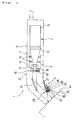
- An image pick-up apparatus 1 includes an imaging means 2, an optical means 3 and a light source means 4, which are enclosed within a case 5. It is of a size which permits the apparatus to be grasped easily by one hand. Its front end portion is bent in an inclined state so as to be suitable for observing the face skin while the apparatus is held by one hand.
- the imaging means 2 comprises an imaging device 10 using a CCD and a control circuit unit 13 for controlling the imaging device 10 and for amplifying an image signal.
- the optical means 3 comprises an optical lens 14 and plural flare stops 15, 15, ....
- the flare stops 15, 15, ... are provided projectingly in an annular form to form a minimum optical path T required.
- the formation of such optical path T by the flare stops 15, 15, ... is extremely useful in obtaining a clear image.
- a polarizing unit 16 is disposed just in front of the optical lens 14. Further, in the optical path between the optical lens 14 and an objection M to be observed there is disposed a reflecting mirror 17 in a front position with respect to the polarizing unit 16.
- the polarizing unit 16 comprises a second polarizer 18 and a polarization plane rotating means 19.
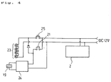
- Polarized light obtained by a first polarizer 22 which will be described later can be shut off by turning ON a non-reflection image switch 21 provided on the outer surface of the case 5.
- a liquid crystal is used as the polarization plane rotating means 19.
- lamps 23, 23, ... of the light source means 4 which will be described later go on and an oscillator 24 operates, so that the polarization plane rotating means 19 causes the polarization plane of polarized light to rotate 90 ° and hence the polarized light obtained by the first polarizer 22 is cut off by the second polarizer 18.
- the non-reflection image switch 21 is OFF, the polarized light can pass through the second polarizer 18.
- the light from the object M to be observed is classified into a surface reflected light reflected directly by the surface of the object M and a non-surface reflected light which has once passed through the surface layer of the object M.
- the surface reflected light retains the polarizability obtained by the first polarizer 22, whereas the non-surface reflected light loses polarizability and becomes a natural light. Therefore, an image containing such surface reflected light and an image not containing it can be observed selectively according to whether the polarized light is allowed to pass or cut off.
- the polarizing unit 16 is disposed just in front of the optical lens 14 is that the maximum operating temperature of the polarization plane rotating means 19 using liquid crystal is about 40 ° C, but the temperature near the light source means 4 which will be described later sometimes exceeds the maximum operating temperature, so at such a higher temperature the polarization plane rotating means 19 may not operate accurately.
- the reflecting mirror 17 is provided for changing the optical path in accordance with the inclination of the front end portion mentioned previously. It is a surface reflection type. More specifically, a reflective surface of the reflecting mirror 17 is exposed and light is reflected directly by the exposed reflective surface, unlike an ordinary type of mirror in which a reflective surface is formed at the back of a transparent material (e.g. glass) and light passes through the transparent material at the time of reflection.
- a transparent material e.g. glass
- the use of such a surface reflection type reflecting mirror is related to the foregoing polarization. More particularly, since the polarizing unit 16 must be disposed in a position rearer than the reflecting mirror 17 for the reason stated above, the passage of polarized light through a transparent material will result in the polarizability thereof being disturbed, thus making it impossible to effect accurately such observation using polarized light as mentioned above.
- the light source means 4 comprises a lamp unit 26, a diffusion preventing mirror 27 and a lighting/processing unit 28.
- the lamp unit 26 comprises a plurality (four in this embodiment) of lamps 23, 23, ... arranged side by side on a board 29. If can be mounted and removed through the board 29 with respect to a mounting hole 30 formed in the case 5.
- the four lamps 23, 23, ... are connected in series, and assuming that a rated voltage of each lamp 23 is 2.5V, a voltage of 12V is applied to the series-connected lamps. This is because by applying a voltage 20% higher than the total rated voltage of 10V of the four lamps 23, 23, ... there is obtained brightness which is twice the brightness obtained at such rated voltage. On the other hand, the service life is reduced to about one tenth.
- the reason why the lamps 23, 23, ... are connected in series is that it is intended to reduce the size of the lamp unit 26 and simplify the structure of an electric system, for mounting in a narrow space. More specifically, the size of each lamp is reduced by using a lamp of 2.5V in rated voltage to thereby attain the reduction in size of the lamp unit 26, and a power supply of 12V necessary for the oscillator 24 can be used also for the lamp unit 26 without using a transformer to thereby simplify the structure of the electric system.
- terminal pins 33p of connecting terminals 33 are fitted in the terminal receiving holes 32, 32 to make connection with a power-supply circuit 34 in Fig. 4.
- the reason why the lamp 26 is constituted as above and made detachable wholly as one unit is that the replacement thereof should be done in a simple manner to further facilitate the use thereof since the service life of the lamp 23 is sacrificed for attaining a stronger brightness as noted previously.
- the diffusion preventing mirror 27 is for preventing the light from the lamps 23, 23, ... from entering the optical path of the optical means 3 directly and for directing the light efficiently to the object M to be observed.
- the mirror 27 is provided so as to cover the lamps 23, 23, ... from above like eaves.
- the lighting/processing unit 28 comprises a diffuser panel 35, a heat rays absorbing plate 36 and the first polarizer 22, which are arranged in this order successively from the side closer to the lamp unit 26 so as to intersect the radiation of light from the lamp unit.
- the heat rays absorbing plate 36 functions to remove heat rays from the light emitted from the lamps 23, 23, ..., thereby preventing the rise of the internal temperature of the case 5.
- the first polarizer 22 functions to polarize the light emitted from the lamps 23, 23 .... The lighting using the resulting polarized light is utilized as explained previously.
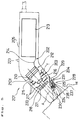
- An image pick-up apparatus 201 is basically the same as in the first embodiment, as shown in Fig. 5, and it comprises an imaging means 202, an optical means 203, and a light source means 204, which are enclosed in a case 205.
- the image pick-up apparatus 201 has a body portion of a size which permits the user to grasp the body portion easily by one hand.
- a front end portion of the apparatus 201 is bent in an inclined state with respect to the body portion to suit the observation of, for example, the face skin while the body portion is held by one hand.
- the imaging means 202 like the imaging means 2 in the first embodiment, comprises an imaging device 210 using a CCD and a control circuit unit 213 for controlling the imaging device 210 and for amplifying an image signal. But a difference from the imaging means 2 in the first embodiment is recognized in that the imaging device 210 is connected to the control circuit unit 213 through a flexible cable 214, that is, the imaging device 210 is rendered movable freely with respect to the control circuit unit 213.
- the imaging device 210 is disposed in such a manner that a light receiving surface 210f of the imaging device 210 is orthogonal to an optical axis A of an image light which is incident front the bent front portion of the image pick-up apparatus, that is, in such a manner as to eliminate the necessity of changing the optical axis of the image light.
- the color filter 215 functions to adjust the wavelength characteristics of light which enters the imaging device 210, in accordance with color characteristics of the imaging device.
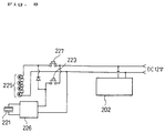
- optical means 203 As other components there are used optical means 203, optical lens 216, flare stops 217, polarizing unit 218, second polarizer 220, polarization plane rotating means 221, non-reflection image switch 223, first polarizer 224, light source means 204, lamp 225, oscillator 226, reflection image switch 227, lamp unit 228, diffusion preventing mirror 229, lighting/processing unit 230, partial power-supply circuit 231, terminal receiving hole 234, mounting hole 232, connecting terminal 235, terminal pin 235p, diffuser panel 237, and heat rays absorbing plate 238. Since these components are the same as in the first embodiment, explanations thereof are here omitted.
- the image pick-up apparatus 302 contains an optical system unit 310 and an imaging unit 311, and is also provided with a lighting unit 312.
- the image pick-up apparatus 302 is used as in Fig. 11.
- An image picked up by the apparatus 302 is reproduced on a display 304 of a display apparatus 303 and is observed.
- the image pick-up apparatus 302 and the display apparatus 303 combine as a set and constitute a magnifying observation apparatus 301.
- the optical unit 310 comprises an objective lens 313 and plural flare stops 314, 314, .... Since the flare stops 314, 314, ... are formed projectingly in an annular shape to form a minimum optical path T required, the formation of such optical path T by those flare stops is extremely useful in obtaining a clear image.
- the imaging unit 311 comprises an imaging device 315 and a control circuit unit 318 for controlling the imaging device 315 and for amplifying an image signal, the imaging device 315 and the control circuit unit 318 being connected with each other through a flexible cable 319.
- the objective lens 313, flare stops 314, 314, ... and imaging device 315 of both optical system 310 and imaging unit 311 are adapted to slide like arrow X in interlock with each other by means of a slide mechanism which utilizes a cam structure.
- the slide mechanism comprises a plurality of holding cylinders 321 (321a, 321b, 321c, 321d) for the optical system and for the imaging device, with roller projections 320 (320a, 320b, 320c, 320d) being formed on the periphery of the cylinders 321; an intermediate cylinder 323 having rectilinear guide slots 322 formed in the periphery thereof; and a cam cylinder 325 having cam slots 324 (324a, 324b, 324c, 324d) for the optical system and for the imaging device, formed on the periphery thereof.
- holding cylinders are combined together so that the holding cylinders 321a, 321b, 321c and 321d are held slidably by the intermediate cylinder 323, which in turn is held by the cam cylinder 325 in a relatively rotatable manner.
- the roller projections 320a, 320b, 320c and 320d are all individually restricted their movement by the cam slots 324a, 324b, 324c and 324d which are each formed in a predetermined curvilinear shape, whereby the holding cylinders 321a, 321b, 321c and 321d are allowed to slide like arrow X.
- the holding cylinders 321a, 321b, 321c and 321d are restricted their movement by the guide slots 322 of the intermediate cylinder 323, they are prevented from rotating with the rotation of the cam cylinder 325. Consequently, the objective lens 313, flare stops 314, 314, ... and imaging device 315, which are held in a fixed state by the holding cylinders 321a, 321b, 321c and 321d, slide interlockedly while maintaining a predetermined relation.
- the lighting unit 312 comprises a light source 327 and a light condensing guide 328 for radiating light from the light source 327 efficiently to a portion to be observed.
- light from an external light-source lamp (not shown) is conducted up to the image pick-up apparatus, using a bundle of optical fibers extending through a cable 329, and front ends for irradiation of optical fibers 329f, 329f, ... of such optical fiber bundle are implanted in an annular holding member 330.
- Light radiated from the irradiating front ends of the so-arranged optical fibers 329f, 329f, ... reaches an incident end face 330 formed at a base end of the light condensing guide 328 which will be described below.
- the light condensing guide 328 is formed in a hollow semi spherical shape or a cylindrical shape having a hollow semispherical front portion, using a transparent material, e.g. an acrylic resin.
- a base end of its rear end portion is formed as the incident end face 330, and a through hole 331 is formed centrally of its front portion.
- the light radiated from the light source 327 through the incident end face 330 travels through the solid interior under total reflection and is conducted up to the through hole 331, then radiates the portion to be observed of the object M in a nearly horizontal state from the inside surface of the hole.
- the light condensing guide 32B also has a focusing function. With its front end abutted to the object N to be observed, the objective lens 313 is focused on the object M.
- the simple zoom structure thereof is applied to the method in which light is conducted through a bundle of optical fibers from an external light-source lamp, that is, an external light-source lamp method, it can be done easily by those skilled in the art to apply the simple zoom structure of this embodiment to such a light-source lamp built-in type structure as in each of the first and second embodiments on the basis of this third embodiment.
Landscapes
- Physics & Mathematics (AREA)
- Engineering & Computer Science (AREA)
- Electromagnetism (AREA)
- General Physics & Mathematics (AREA)
- Signal Processing (AREA)
- Multimedia (AREA)
- Artificial Intelligence (AREA)
- Computer Vision & Pattern Recognition (AREA)
- Toxicology (AREA)
- Theoretical Computer Science (AREA)
- Optics & Photonics (AREA)
- General Health & Medical Sciences (AREA)
- Health & Medical Sciences (AREA)
- Microscoopes, Condenser (AREA)
- Studio Devices (AREA)
Applications Claiming Priority (7)
| Application Number | Priority Date | Filing Date | Title |
|---|---|---|---|
| JP59676/91U | 1991-07-04 | ||
| JP189569/91 | 1991-07-04 | ||
| JP59677/91U | 1991-07-04 | ||
| JP059677U JPH056984U (ja) | 1991-07-04 | 1991-07-04 | 拡大観察装置の対物具 |
| JP3189569A JPH0511180A (ja) | 1991-07-04 | 1991-07-04 | 簡易ズーム式の撮像機構及びこれを用いた観察装置 |
| JP059676U JPH056983U (ja) | 1991-07-04 | 1991-07-04 | 拡大観察装置の対物具 |
| PCT/JP1992/000836 WO1993001686A1 (en) | 1991-07-04 | 1992-07-02 | Magnifying observation apparatus |
Publications (3)
| Publication Number | Publication Date |
|---|---|
| EP0547232A1 true EP0547232A1 (de) | 1993-06-23 |
| EP0547232A4 EP0547232A4 (en) | 1994-10-26 |
| EP0547232B1 EP0547232B1 (de) | 1998-10-21 |
Family
ID=27296966
Family Applications (1)
| Application Number | Title | Priority Date | Filing Date |
|---|---|---|---|
| EP92913998A Expired - Lifetime EP0547232B1 (de) | 1991-07-04 | 1992-07-02 | Vorrichtung für vergrösserte beobachtung |
Country Status (6)
| Country | Link |
|---|---|
| US (1) | US5442489A (de) |
| EP (1) | EP0547232B1 (de) |
| KR (1) | KR970011270B1 (de) |
| DE (1) | DE69227355T2 (de) |
| SG (1) | SG43273A1 (de) |
| WO (1) | WO1993001686A1 (de) |
Cited By (1)
| Publication number | Priority date | Publication date | Assignee | Title |
|---|---|---|---|---|
| US11175488B2 (en) | 2016-02-18 | 2021-11-16 | Oculyze Gmbh | Mobile microscope assembly |
Families Citing this family (11)
| Publication number | Priority date | Publication date | Assignee | Title |
|---|---|---|---|---|
| US5742392A (en) * | 1996-04-16 | 1998-04-21 | Seymour Light, Inc. | Polarized material inspection apparatus |
| US20050046830A1 (en) * | 1999-04-16 | 2005-03-03 | John Karp | Polarized material inspection apparatus and system |
| US6697156B1 (en) * | 2000-04-05 | 2004-02-24 | John Karp | Polarized material inspection apparatus |
| US6993167B1 (en) | 1999-11-12 | 2006-01-31 | Polartechnics Limited | System and method for examining, recording and analyzing dermatological conditions |
| WO2001067956A2 (de) * | 2000-03-11 | 2001-09-20 | Rodenstock Präzisionsoptik Gmbh & Co. Kg | Dermatologie-bildaufnahmesystem |
| US7253949B2 (en) * | 2002-12-17 | 2007-08-07 | Piontkowski Paul K | Stereo microscope |
| US7564990B2 (en) * | 2005-08-18 | 2009-07-21 | Nu Skin International, Inc. | Imaging system and method for physical feature analysis |
| WO2013113760A1 (de) | 2012-01-30 | 2013-08-08 | Leica Microsystems Cms Gmbh | Mikroskop mit kabelloser funkschnittstelle und mikroskopsystem |
| US10036881B2 (en) | 2014-05-23 | 2018-07-31 | Pathonomic | Digital microscope system for a mobile device |
| US11730356B2 (en) | 2017-11-06 | 2023-08-22 | Vision Products, Llc | Mobile ophthalmic device |
| US11395714B2 (en) | 2019-11-11 | 2022-07-26 | Dermlite Llc | Medical illuminator with variable polarization |
Citations (1)
| Publication number | Priority date | Publication date | Assignee | Title |
|---|---|---|---|---|
| JPS6286322A (ja) * | 1985-10-11 | 1987-04-20 | Olympus Optical Co Ltd | 側視型内視鏡 |
Family Cites Families (12)
| Publication number | Priority date | Publication date | Assignee | Title |
|---|---|---|---|---|
| US3625607A (en) * | 1969-05-22 | 1971-12-07 | Warren Childers | Automatic focusing camera |
| US3621131A (en) * | 1969-11-21 | 1971-11-16 | Us Navy | Visual environment simulator |
| JPS5123339Y2 (de) * | 1972-09-26 | 1976-06-15 | ||
| US4176923A (en) * | 1978-10-10 | 1979-12-04 | Collender Robert B | Stereoscopic motion picture large scale scanning reproduction method and apparatus |
| JPS61296869A (ja) * | 1985-06-25 | 1986-12-27 | Matsushita Electric Works Ltd | ドアホン子器 |
| JPS6273877A (ja) * | 1985-09-27 | 1987-04-04 | Toshiba Corp | Tv式内視鏡装置 |
| JPH07122690B2 (ja) * | 1987-04-01 | 1995-12-25 | 株式会社エルモ社 | 接写装置 |
| DE3822303A1 (de) * | 1987-12-10 | 1989-06-22 | Birkle Gebhard | Vorrichtung zum optischen abtasten der oberflaeche eines objektes, dessen oberflaeche licht zu reflektieren oder streuen imstande ist und verfahren hierzu |
| US4881128A (en) * | 1988-05-11 | 1989-11-14 | Asahi Research Corporation | Video camera and recorder system with illumination control features |
| JPH01308527A (ja) * | 1988-06-07 | 1989-12-13 | Sukara Kk | 拡大撮像装置における照明用導光装置 |
| CA2009129C (en) * | 1989-02-04 | 1995-02-14 | Mitsubishi Chemical Corporation | Image pickup head for image pickup device |
| JP2950944B2 (ja) * | 1990-08-28 | 1999-09-20 | スカラ株式会社 | 拡大観察装置 |
-
1992
- 1992-07-02 DE DE69227355T patent/DE69227355T2/de not_active Expired - Lifetime
- 1992-07-02 WO PCT/JP1992/000836 patent/WO1993001686A1/ja active IP Right Grant
- 1992-07-02 EP EP92913998A patent/EP0547232B1/de not_active Expired - Lifetime
- 1992-07-02 KR KR1019930700649A patent/KR970011270B1/ko not_active IP Right Cessation
- 1992-07-02 SG SG1996006796A patent/SG43273A1/en unknown
-
1994
- 1994-09-23 US US08/311,724 patent/US5442489A/en not_active Expired - Lifetime
Patent Citations (1)
| Publication number | Priority date | Publication date | Assignee | Title |
|---|---|---|---|---|
| JPS6286322A (ja) * | 1985-10-11 | 1987-04-20 | Olympus Optical Co Ltd | 側視型内視鏡 |
Non-Patent Citations (2)
| Title |
|---|
| No further relevant documents disclosed * |
| See also references of WO9301686A1 * |
Cited By (1)
| Publication number | Priority date | Publication date | Assignee | Title |
|---|---|---|---|---|
| US11175488B2 (en) | 2016-02-18 | 2021-11-16 | Oculyze Gmbh | Mobile microscope assembly |
Also Published As
| Publication number | Publication date |
|---|---|
| US5442489A (en) | 1995-08-15 |
| WO1993001686A1 (en) | 1993-01-21 |
| EP0547232A4 (en) | 1994-10-26 |
| SG43273A1 (en) | 1997-10-17 |
| KR970011270B1 (ko) | 1997-07-08 |
| EP0547232B1 (de) | 1998-10-21 |
| KR930702861A (ko) | 1993-09-09 |
| DE69227355T2 (de) | 1999-03-18 |
| DE69227355D1 (de) | 1998-11-26 |
Similar Documents
| Publication | Publication Date | Title |
|---|---|---|
| US6101028A (en) | Miniature microscope | |
| US5709459A (en) | Surgical luminaire | |
| EP0547232B1 (de) | Vorrichtung für vergrösserte beobachtung | |
| US6898004B2 (en) | Microscope system | |
| US7554727B2 (en) | Illumination apparatus for microscope | |
| US5497267A (en) | Video microscope | |
| US7394979B2 (en) | Camera adapter for optical devices, in particular microscopes | |
| US6964508B2 (en) | Fiber optic bundle lighting units providing focused illumination | |
| US4859032A (en) | Hand-held magnifier apparatus | |
| US4285568A (en) | Microscope stage | |
| US6195203B1 (en) | Apparatus for direct optical fiber through-lens illumination of microscopy or observational objects | |
| US7304794B2 (en) | Microscope | |
| US5566020A (en) | Microscopy system | |
| JP4063469B2 (ja) | 超微小空隙から内部を観察するための装置 | |
| JP2768470B2 (ja) | 実体顕微鏡 | |
| JPH0627393A (ja) | 観察装置 | |
| US4455592A (en) | High intensity illumination light table with attenuating means coupled to rhomboid arms | |
| JP2003177325A (ja) | 全反射蛍光顕微鏡 | |
| US4899188A (en) | Light scattering optic guide | |
| US4455593A (en) | High intensity illumination light table with attenuating and reflecting means coupled to rhomboid arms | |
| JPH0511180A (ja) | 簡易ズーム式の撮像機構及びこれを用いた観察装置 | |
| JP3321260B2 (ja) | 外観検査装置 | |
| JPH11298782A (ja) | デンタルビデオマイクロスコープ | |
| US4727858A (en) | High intensity selectable poly or monochromatic slit light source apparatus for optical instruments | |
| KR200174671Y1 (ko) | 화상 현미경 |
Legal Events
| Date | Code | Title | Description |
|---|---|---|---|
| PUAI | Public reference made under article 153(3) epc to a published international application that has entered the european phase |
Free format text: ORIGINAL CODE: 0009012 |
|
| 17P | Request for examination filed |
Effective date: 19930319 |
|
| AK | Designated contracting states |
Kind code of ref document: A1 Designated state(s): DE FR GB |
|
| A4 | Supplementary search report drawn up and despatched | ||
| AK | Designated contracting states |
Kind code of ref document: A4 Designated state(s): DE FR GB |
|
| RAP1 | Party data changed (applicant data changed or rights of an application transferred) |
Owner name: MITSUBISHI CHEMICAL CORPORATION Owner name: SCALAR CORPORATION |
|
| 17Q | First examination report despatched |
Effective date: 19961223 |
|
| GRAG | Despatch of communication of intention to grant |
Free format text: ORIGINAL CODE: EPIDOS AGRA |
|
| GRAG | Despatch of communication of intention to grant |
Free format text: ORIGINAL CODE: EPIDOS AGRA |
|
| GRAH | Despatch of communication of intention to grant a patent |
Free format text: ORIGINAL CODE: EPIDOS IGRA |
|
| GRAH | Despatch of communication of intention to grant a patent |
Free format text: ORIGINAL CODE: EPIDOS IGRA |
|
| GRAA | (expected) grant |
Free format text: ORIGINAL CODE: 0009210 |
|
| STAA | Information on the status of an ep patent application or granted ep patent |
Free format text: STATUS: THE PATENT HAS BEEN GRANTED |
|
| AK | Designated contracting states |
Kind code of ref document: B1 Designated state(s): DE FR GB |
|
| REF | Corresponds to: |
Ref document number: 69227355 Country of ref document: DE Date of ref document: 19981126 |
|
| ET | Fr: translation filed | ||
| PLBE | No opposition filed within time limit |
Free format text: ORIGINAL CODE: 0009261 |
|
| 26N | No opposition filed | ||
| REG | Reference to a national code |
Ref country code: GB Ref legal event code: IF02 |
|
| PGFP | Annual fee paid to national office [announced via postgrant information from national office to epo] |
Ref country code: FR Payment date: 20110816 Year of fee payment: 20 Ref country code: GB Payment date: 20110727 Year of fee payment: 20 Ref country code: DE Payment date: 20110727 Year of fee payment: 20 |
|
| REG | Reference to a national code |
Ref country code: DE Ref legal event code: R071 Ref document number: 69227355 Country of ref document: DE |
|
| REG | Reference to a national code |
Ref country code: DE Ref legal event code: R071 Ref document number: 69227355 Country of ref document: DE |
|
| REG | Reference to a national code |
Ref country code: GB Ref legal event code: PE20 Expiry date: 20120701 |
|
| PG25 | Lapsed in a contracting state [announced via postgrant information from national office to epo] |
Ref country code: GB Free format text: LAPSE BECAUSE OF EXPIRATION OF PROTECTION Effective date: 20120701 |
|
| PG25 | Lapsed in a contracting state [announced via postgrant information from national office to epo] |
Ref country code: DE Free format text: LAPSE BECAUSE OF EXPIRATION OF PROTECTION Effective date: 20120703 |