US7554727B2 - Illumination apparatus for microscope - Google Patents
Illumination apparatus for microscope Download PDFInfo
- Publication number
- US7554727B2 US7554727B2 US11/971,833 US97183308A US7554727B2 US 7554727 B2 US7554727 B2 US 7554727B2 US 97183308 A US97183308 A US 97183308A US 7554727 B2 US7554727 B2 US 7554727B2
- Authority
- US
- United States
- Prior art keywords
- light
- sample
- illumination
- orientation member
- light source
- Prior art date
- Legal status (The legal status is an assumption and is not a legal conclusion. Google has not performed a legal analysis and makes no representation as to the accuracy of the status listed.)
- Active
Links
Images


Classifications
-
- G—PHYSICS
- G02—OPTICS
- G02B—OPTICAL ELEMENTS, SYSTEMS OR APPARATUS
- G02B17/00—Systems with reflecting surfaces, with or without refracting elements
- G02B17/006—Systems in which light light is reflected on a plurality of parallel surfaces, e.g. louvre mirrors, total internal reflection [TIR] lenses
-
- G—PHYSICS
- G02—OPTICS
- G02B—OPTICAL ELEMENTS, SYSTEMS OR APPARATUS
- G02B21/00—Microscopes
- G02B21/06—Means for illuminating specimens
-
- G—PHYSICS
- G02—OPTICS
- G02B—OPTICAL ELEMENTS, SYSTEMS OR APPARATUS
- G02B21/00—Microscopes
- G02B21/06—Means for illuminating specimens
- G02B21/08—Condensers
- G02B21/086—Condensers for transillumination only
Definitions
- the present invention relates to an illumination apparatus for a microscope.
- Japanese Patent No. 3194909 discloses a microscope using a planar fluorescent lamp for illumination of a microscope.
- Jpn. Pat. Appln. KOKAI Publication No. 7-122694 discloses a planar light source in which a light diffuser is arranged between a light source having LEDs aligned in an array and a sample.
- a light source having a diffuser with an increased surface is used in order to cover an illumination range with a low magnification of, e.g., a stereoscopic microscope.
- the present invention is directed to an illumination apparatus for a microscope.
- An illumination apparatus according to the present invention has an optically transparent sample mount plate on which a sample is mounted, a surface light source that projects substantially uniform illumination light toward the sample mount plate, and a light orientation member that restricts diffusion of the illumination light in relation to at least one direction.
- Another illumination apparatus has a surface light source that has a light projection surface from which emitted light is projected, and projects illumination light with a projection angle in a predetermined range that is substantially rotation-symmetrical with respect to an optical axis vertical to the light projection surface; a light shielding plate that is arranged between a sample arranged facing the light projection surface and the light projection surface, and shields light that is directly applied to the sample from the light projection surface; and a reflection illumination member that is arranged around the optical axis between the sample and the light projection surface, and reflects the illumination light to illuminate the sample.
- a still another illumination apparatus has a surface light source that has a light projection surface from which emitted light is projected, and projects illumination light with a projection angle in a predetermined range that is substantially rotation-symmetrical with respect to an optical axis vertical to the light projection surface; at least one light orientation member that is arranged between a sample arranged facing the light projection surface and the light projection surface, and restricts a transmission angle of light projected from the light protection surface in a plane containing at least the optical axis; and a reflection illumination member that is arranged around the optical axis between the sample and the light orientation member, and reflects the illumination light transmitted through the light orientation member to illuminate the sample.
- FIG. 1 schematically shows a microscope having a built-in transmission illumination apparatus according to a first embodiment of the present invention
- FIG. 2 is a perspective view schematically showing a configuration of a louver film depicted in FIG. 1 ;
- FIG. 3A schematically shows a cross section in a Y direction of the transmission illumination apparatus according to the first embodiment of the present invention
- FIG. 3B schematically shows a cross section in an X direction of the transmission illumination apparatus according to the first embodiment of the present invention
- FIG. 4 is a perspective view schematically showing a configuration of a louver film in a first modification of the first embodiment according to the present invention
- FIG. 5 schematically showing a cross section in the Y direction of a transmission illumination apparatus comprising the louver film depicted in FIG. 4 ;
- FIG. 6A schematically shows a cross section in the Y direction of a transmission illumination apparatus of a second modification of the first embodiment according to the present invention
- FIG. 6B schematically shows a cross section in the X direction of the transmission illumination apparatus of the second modification of the first embodiment according to the present invention
- FIG. 7A is a plan view of an upper louver film unit depicted in FIGS. 6A and 6B ;
- FIG. 7B is a plan view of a lower louver film unit depicted in FIGS. 6A and 6B ;
- FIG. 7C shows a state in which the louver film depicted in FIG. 7A and the louver film depicted in FIG. 7B are overlapped
- FIG. 8 schematically shows a cross section in the X direction of a transmission illumination apparatus in a third modification of the first embodiment according to the present invention
- FIG. 9A is a plan view of an upper louver film unit depicted in FIG. 8 ;
- FIG. 9B is a plan view of a lower louver film unit depicted in FIG. 8 ;
- FIG. 9C shows a state in which the louver film depicted in FIG. 9A and the louver film depicted in FIG. 9B are overlapped
- FIG. 9D shows a state in which the louver film depicted in FIG. 9A and the louver film depicted in FIG. 9B are overlapped with a different inclination with respect to the X direction;
- FIG. 10A schematically shows a cross section in the X direction of a primary part of a transmission illumination apparatus according to a second embodiment of the present invention
- FIG. 10B schematically shows a cross section in the Y direction of the primary part of the transmission illumination apparatus according to the second embodiment of the present invention
- FIG. 11A schematically shows a cross section in the Y direction in a state where the louver film is parallel to a glass plate in the transmission illumination apparatus depicted in FIGS. 10A and 10B ;
- FIG. 11B schematically shows a cross section in the Y direction in a state where the louver film is inclined with respect to the glass plate at the maximum in the transmission illumination apparatus depicted in FIGS. 10A and 10B ;
- FIG. 12 schematically shows a cross section in the X direction of a primary part of a transmission illumination apparatus according to a third embodiment of the present invention
- FIG. 13 is a top view of a turret depicted in FIG. 12 ;
- FIG. 14 is a schematic view showing a configuration of an illumination apparatus according to a fourth embodiment of the present invention.
- FIG. 15 is a plan view showing a configuration of the illumination apparatus depicted in FIG. 14 ;
- FIG. 16 is a cross-sectional view illustrating an illumination state by the illumination apparatus depicted in FIG. 14 ;
- FIG. 17 is a schematic view showing a configuration of an illumination apparatus according to a fifth embodiment of the present invention.
- FIG. 18A is a perspective view showing a partial configuration of a light orientation member depicted in FIG. 17 ;
- FIG. 18B is a cross-sectional view illustrating a state of a transmitted light of the light orientation member depicted in FIG. 17 ;
- FIG. 19 is a plan view showing a configuration of the illumination apparatus depicted in FIG. 17 ;
- FIG. 20 is a cross-sectional view illustrating an illumination state by the illumination apparatus depicted in FIG. 17 ;
- FIG. 21 is a cross-sectional view showing a modified configuration of the illumination apparatus according to the fifth embodiment of the present invention.
- FIG. 22 is a plan view showing a configuration of the light orientation member depicted in FIG. 21 ;
- FIG. 23 is a plan view showing a configuration of the illumination apparatus depicted in FIG. 21 ;
- FIG. 24 is a schematic view showing a configuration of an illumination apparatus according to a sixth embodiment of the present invention.
- FIG. 25 is a plan view showing a configuration of the illumination apparatus depicted in FIG. 24 ;
- FIG. 26 is a perspective view showing a partial configuration of the light orientation member depicted in FIG. 24 ;
- FIG. 27A is a cross-sectional view in the Y direction illustrating an illumination state by the illumination apparatus depicted in FIG. 24 ;
- FIG. 27B is a cross-sectional view in the X direction illustrating an illumination state by the illumination apparatus depicted in FIG. 24 ;
- FIG. 28A is a cross-sectional view illustrating an effect on a shadow by the light orientation member depicted in FIG. 24 ;
- FIG. 28B is a cross-sectional view illustrating an effect on a shadow by the light orientation member depicted in FIG. 24 ;
- FIG. 29 is a cross-sectional view illustrating an effect that emphasizes the shadow by illumination using a light orientation member having inclined opaque members
- FIG. 30 is a schematic view showing a modified configuration of an illumination apparatus according to a sixth embodiment of the present invention.
- FIG. 31A is a plan view showing a configuration of the illumination apparatus depicted in FIG. 30 ;
- FIG. 31B is a plan view showing a configuration of the illumination apparatus depicted in FIG. 30 ;
- FIG. 32 is a cross-sectional view illustrating an effect on the shadow and illumination light quantity by the light orientation member depicted in FIG. 30 ;
- FIG. 33 is a schematic view showing a configuration of an illumination apparatus according to a seventh embodiment of the present invention.
- FIG. 34 is a plan view showing a partial configuration of the illumination apparatus depicted in FIG. 33 .
- FIG. 1 schematically shows a microscope having a built-in transmission illumination apparatus according to a first embodiment of the present invention.
- a transmission illumination stand 1 as a microscope stand has a base portion 1 a arranged in the horizontal direction, and a support column portion 1 b provided upright with respect to the base portion 1 a .
- the support column portion 1 b is provided with a sighting device 2 .
- the sighting device 2 has a non-illustrated built-in sighting mechanism, and the sighting mechanism is used to move up and down a movable portion 2 b with respect to a fixed portion 2 a in accordance with an operation of a sighting handle 12 .
- the movable portion 2 b of the sighting device 2 is provided with a zoom main body 3 , and the zoom main body 3 allows varying a magnification in accordance with an operation of a zoom handle 13 .
- a lower portion of the zoom main body 3 is provided with a objective lens 4 .
- An upper portion of the zoom main body 3 is provided with a body tube 5 , and the body tube 5 is provided with an eyepiece lens 6 for observation.
- a hole portion 1 a 1 is formed on an upper surface of the base portion 1 a , which faces the objective lens 4 .
- a glass plate 7 which is an optically transparent sample mount plate on which a sample 8 is mounted, is fitted in the hole portion 1 a 1 .
- a surface light source 10 which projects substantially uniform illumination light toward the glass plate 7 , is provided below the glass plate 7 .
- a power supply 11 is connected to the surface light source 10 , a non-illustrated commercial power source is connected to the power supply 11 , and the power is supplied to the surface light source 10 by a non-illustrated switch.
- a light orientation member 9 is provided between the glass plate 7 and the surface light source 10 . The light orientation member 9 restricts diffusion of illumination light projected from the surface light source 10 in relation to at least one direction.
- the light orientation member 9 is supported by a holding portion 1 a 2 formed to the base portion 1 a.
- the transmission illumination apparatus comprises the glass plate 7 on which the sample 8 is mounted, the surface light source 10 that projects substantially uniform illumination light toward the glass plate 7 , and the light orientation member 9 that restricts diffusion of illumination light projected from the surface light source 10 in relation to at least one direction.
- a right-and-left direction seen from a microscopic examiner side (a direction vertical to the page space of FIG. 1 ) is determined as an X direction and a lengthwise direction (a right-and-left direction of the page space of FIG. 1 ) is determined as a Y direction.
- the light orientation member 9 comprises a louver film.
- FIG. 2 is a perspective view schematically showing a configuration of the louver film.
- the louver film 9 comprises an parallel-plate type transparent resin 21 that is optically transparent, and many optically opaque micro louvers 22 that are arranged in the transparent resin 21 at equal intervals.
- the micro louvers 22 of the louver film 9 are perpendicular to the parallel planes of the transparent resin 21 .
- Such a louver film is commercial available from, e.g., Sumitomo 3M Ltd. or Shin-Etsu Polymer Co., Ltd.
- the louver film 9 shown in FIG. 2 is drawn in a rectangular shape in order to schematically illustrate its configuration, the louver film 9 may have a circular shape or the like in accordance with the shape of the surface light source 10 .
- the louver film 9 is arranged in such a manner that the micro louvers 22 become parallel to the X direction as shown in FIG. 2 , for example.
- Such an arrangement is particularly beneficial when the microscope is a binocular stereoscopic microscope as will be described later.
- Focusing with respect to the sample 8 on the glass plate 7 is adjusted by rotating the sighting handle 12 while looking through the eyepiece lens 6 by an observer so that the zoom main body 3 and the objective lens 4 are moved up and down together with the movable portion 2 b of the sighting device 2 .
- a magnification of an observed sample image can be increased/reduced within an arbitrary range by changing a magnification in the zoom main body 3 while rotating the zoom handle 13 .
- FIG. 3A schematically shows a cross section in the Y direction of the transmission illumination apparatus according to this embodiment
- FIG. 3B schematically shows a cross section in the X direction of the transmission illumination apparatus of this embodiment.
- illumination light projected from the surface light source 10 enters the louver film 9 .
- the illumination light having a large incidence angle is shielded by the micro louvers 22 and does not reach the sample 8 . Therefore, the sample 8 is illuminated with the illumination light having a relatively small incidence angle.
- Arrows denoted by reference numeral 31 in FIG. 3A indicate the illumination light having a maximum incidence angle that can be illuminate the sample 8 .
- FIG. 3A schematically shows a cross section in the Y direction of the transmission illumination apparatus according to this embodiment
- FIG. 3B schematically shows a cross section in the X direction of the transmission illumination apparatus of this embodiment.
- FIGS. 3A and 3B illumination light projected from the surface light source 10 enters the louver film 9 .
- the illumination light having a large incidence angle is shielde
- the sample 8 is illuminated with the illumination light having an incidence angle smaller than the possible maximum incidence angle that can be obtained by the surface light source 10 , i.e., the illumination light having all incidence angles projected from the surface light source 10 .
- the shade is generated in an image of the sample 8 observed through the eyepiece lens 6 in the Y direction, but there is obtained an observation image in which no shadow is generated in the X direction.
- the shadow generated in the Y direction enables observation even if the sample 8 is relatively transparent.
- An intensity of the shadow can be controlled by using each interval (a pitch) between the micro louvers 22 of the louver film 9 .
- the light shielding effect is increased and an illumination angle becomes smaller as the pitch becomes finer, and hence the shadow with a higher intensity can be provided to the sample 8 .
- a length D of a shortest side of a light emission portion of the surface light source 10 , a distance L from a sample mount surface or upper surface of the glass plate 7 to a light emission surface of the surface light source 10 , and a maximum angle (a half angle) A of illumination light that falls on the sample 8 satisfy following conditional expressions: L ⁇ 0.7D A ⁇ 0.9 tan ⁇ 1 ( D/ 2 L ), so that the shadow is provided to the sample 8 to facilitate observation.
- L ⁇ 0.7D represents that the distance between the sample mount surface and the surface light source 10 is close, and the maximum angle (the half angle) A of the illumination light that falls on the sample 8 under this circumstance can satisfy the following condition, A ⁇ 0.9 tan ⁇ 1 ( D/ 2 L ).
- the maximum angle A can be reduced by 10% or more as compared with the case where the surface light source 10 is arranged as it is.
- the surface light source 10 is arranged at a short distance, there can be obtained the effect as if the surface light source 10 is arranged at a long distance.
- the length D of the shortest side of the light emission portion of the surface light source 10 is 50 mm.
- the distance L from the sample mount surface to the light emission surface is less than 35 mm.
- the maximum angle A of the illumination light that falls on the sample 8 is less than 32°.
- the maximum angle A of the illumination light is obtained when the distance from the sample mount surface to the light emission surface is smaller than 35 mm and the surface light source 10 is arranged at a longer distance than 40 mm.
- the maximum angle of the illumination light that falls on the sample 8 becomes 35.5°.
- a binocular stereoscopic microscope generally has two optical axes each of which has an inward angle and that are aligned in the X direction for a right eye and a left eye.
- the binocular stereoscopic microscope when the shadow is generated in the X direction of the sample 8 , how the shadow is generated differs depending on the two optical axes because the two optical axes have different angles. As a result, the shadows of images of the sample 8 that are respectively observed through the right and left eyepiece lenses 6 are different, thereby making it hard to see the images. Therefore, it is preferable that the shadow is not generated in the right-and-left direction (the X direction) of the images with respect to the binocular stereoscopic microscope.
- the microscope is the binocular stereoscopic microscope
- the light orientation member i.e., the louver film 9 to restrict diffusion of the illumination light in relation to a direction vertical to the plane that contains the two optical axes of the binocular stereoscopic microscope.
- the distance between the surface light source 10 and the sample 8 must be increased.
- D is a size of the light emission surface of the surface light source 10
- the surface light source 10 and the sample 8 must be separated from each other by a distance of 0.5D or above, preferably 0.8D or above.
- an appropriate shadow is generated in the images of the sample 8 even if the surface light source 10 is arranged in the vicinity of the sample 8 by the louver film 9 . Therefore, the observation is enabled even in case of a relatively transparent sample. Further, since a thickness of the base portion 1 a of the transmission illumination stand 1 can be reduced, a large movement in the vertical direction that is required in a remounting operation of the sample 8 or the like can be reduced, thereby obtaining the excellent workability.
- a position of hands can be lowered and an eye point can be also lowered, thereby lessening fatigue of an observer.
- the extensive illumination with less unevenness, which provides an appropriate shadow is enabled by increasing the size of the surface light source 10 even if the size of the sample 8 is large.
- louver film 9 in which such micro louvers 22 as shown in FIG. 2 are upright is used in the above embodiment, it is also possible to employ a louver film 9 in which micro louvers 41 are inclined at a fixed angle from the vertical direction as shown in FIG. 4 . That is, in this modification, the micro louvers 41 of the louver film 9 are inclined with respect to the plane of the transparent resin 21 .
- FIG. 5 schematically shows a cross section in the Y direction of a transmission illumination apparatus according to this modification comprising the louver film depicted in FIG. 4 .
- FIG. 5 it is possible to perform an oblique illumination method by which illumination light is obliquely applied to the sample 8 so that the shadow is further emphasized.
- a conventional general oblique illumination method there is known a manner that deflects a mirror arranged in an illumination optical system or a manner that inserts a slit in an illumination optical path. If the mirror or the slit is arranged in the vicinity of a position that is conjugate with respect to a pupil of an observation optical system, there is no unevenness in brightness in a visual field, and the effect of the oblique illumination can be obtained.
- a microscope provided with a variable power device since a conjugate position with respect to the pupil of the observation optical system largely moves with a change in magnifying power, it is impossible to obtain the even oblique illumination in all working states.
- the oblique illumination that provides the shadow with a higher intensity can be performed in the state with no unevenness.
- the light orientation member 9 comprises a louver film and diffusion of illumination light is restricted in the Y direction only in the above-described embodiment, the light orientation member 9 may comprise overlapped louver films in order to provide an appropriate shadow also in the X direction.
- the microscope is a binocular stereoscopic microscope, it is good enough for the light orientation member 9 constituted by overlapping louver films to restrict diffusion of illumination light in relation to the Y direction perpendicular to the plane that contains the two optical axes of the binocular stereoscopic microscope more than diffusion of illumination light in relation to the X direction parallel to the plane that contains the two optical axes of the binocular stereoscopic microscope.
- FIG. 6A schematically shows a cross section in the Y direction of a transmission illumination apparatus according to this modification
- FIG. 6B schematically shows a cross section in the X direction of the transmission illumination apparatus according to this modification
- FIG. 7A is a plan view of an upper louver film 9 b unit depicted in FIGS. 6A and 6B
- FIG. 7B is a plan view of a lower louver film 9 a unit depicted in FIGS. 6A and 6B
- FIG. 7C shows a state in which the louver film 9 b depicted in FIG. 7A and the louver film 9 a illustrated in FIG. 7B are overlapped.
- the light orientation member 9 comprises two louver films 9 a and 9 b .
- one louver film 9 a has micro louvers parallel to the plane that contains the two optical axes of the binocular stereoscopic microscope (i.e., the X direction)
- the other louver film 9 b has micro louvers perpendicular to the plane that contains the two optical axes of the binocular stereoscopic microscope
- each interval between the micro louvers parallel to the plane that contains the two optical axes of the binocular stereoscopic microscope i.e., the X direction
- each interval between the micro louvers parallel to the plane that contains the two optical axes of the binocular stereoscopic microscope i.e., the X direction
- an incidence angle of the illumination light in the direction perpendicular to the plane that contains the two optical axes of the binocular stereoscopic microscope i.e., the Y direction
- an incidence angle of the illumination light in the direction parallel to the plane that contains the two optical axes of the binocular stereoscopic microscope i.e., the X direction
- FIG. 8 schematically shows a cross section in the X direction of a transmission illumination apparatus according to this modification.
- FIG. 9A is a plan view of an upper louver film 9 b unit depicted in FIG. 8
- FIG. 9B is a plan view of a lower louver film 9 a unit depicted in FIG. 8
- FIG. 9C shows a state in which the louver film 9 b depicted in FIG. 9A and the louver film 9 a depicted in FIG. 9B are overlapped
- FIG. 9D shows a state in which the louver film 9 b depicted in FIG. 9A and the louver film 9 a depicted in FIG. 9B are overlapped at a different slant with respect to the X direction.
- the light orientation member 9 comprises the two overlapped louver films 9 a and 9 b like the second modification.
- the two louver films 9 a and 9 b are both arranged with their micro louvers inclined with respect to the plane that contains the two optical axes of the binocular stereoscopic microscope (i.e., the X direction) as shown in FIGS. 9A and 9B .
- a combined pattern of the micro louvers of the two louver films 9 a and 9 b becomes a pattern shown in FIG. 9C .
- the two louver films 9 a and 9 b both are allowed to rotate about an illumination optical axis vertical to the light emission surface of the surface light source 10 , and the combined pattern of the micro louvers of the two louver films 9 a and 9 b can be changed to, e.g., a pattern shown in FIG. 9D by varying the two louver films 9 a and 9 b with respect to the X direction. That is, a level of the illumination light diffusion restriction, i.e., an incidence angle of illumination light can be changed in many ways. As a result, how the shadow is provided can be changed in many ways.
- a diffuser 81 is provided between the glass plate 7 and the light orientation member 9 .
- the diffuser 81 diffuses illumination light to the extent that the diffusion restriction effect for the illumination light by the light orientation member 9 is not substantially affected. Provision of the diffuser 81 can make moire fringes invisible, the moire fringes being generated by superimposition of the two louver films 9 a and 9 b . Additionally, a line of the louver can be made invisible even if the distance between the light orientation member 9 and the sample 8 is small. As a result, a member having a particularly fine pitch does not have to be used for the louver films 9 a and 9 b , and a degree of freedom of selection of the micro louvers can be improved.
- FIG. 10A schematically shows a cross section in the Y direction of a primary part of a transmission illumination apparatus according to a second embodiment of the present invention.
- FIG. 10B schematically shows a cross section in the X direction of the primary part of the transmission illumination apparatus according to the second embodiment of the present invention.
- members denoted by the same reference numerals as those of the members depicted in FIG. 1 are like members, thereby eliminating their detailed explanation.
- the transmission illumination apparatus further comprises a rotation mechanism that rotates the light orientation member 9 about an axis perpendicular to an illumination optical axis vertical to the light emission surface of the surface light source 10 .
- This rotation mechanism roughly has a frame 101 that holds the light orientation member 9 , a shaft 102 fixed to the frame 101 , a bearing 103 that rotatably holds the shaft 102 , and an operation knob portion 104 provided at an end portion of the shaft 102 , as shown in FIGS. 10A and 10B .
- the light orientation member 9 comprises a louver film having the micro louvers perpendicular to the parallel planes of the transparent resin.
- the louver film 9 is held in the frame 101 .
- the frame 101 is fixed at the end portion of the shaft 102 .
- the shaft 102 is rotatably held by the bearing 103 .
- the other end portion of the shaft 102 is provided with the operation knob portion 104 .
- a screw 105 is screwed in the shaft 102 .
- the screw 105 cooperates with a groove 106 provided to the bearing 103 , and serves to restrict a rotation quantity and prevent falling off.
- a hole 107 is formed to the bearing 103 , and a ball 108 , a spring 109 and a machine screw 110 are inserted in the hole 107 .
- the ball 108 is pressed against the shaft 102 by a force of the spring 109 and enables the rotation of the shaft 102 to stop at an arbitrary angle.
- FIG. 11A schematically shows a cross section in the Y direction in a state where the louver film is parallel to the glass plate in the transmission illumination layer according to this embodiment
- FIG. 11B schematically shows a cross section in the Y direction in a state where the louver film is inclined with respect to the glass plate at the maximum in the transmission illumination apparatus in this embodiment.
- illumination light 111 projected from the surface light source 10 is appropriately restricted in relation to diffusion by the louver film 9 and applied to on the sample 8 .
- an appropriate shadow can be provided to observation images of the sample 8 , thereby enabling observation.
- the louver film 9 can be inclined with respect to the glass plate 7 by operating and rotating the operation knob portion 104 .
- louver film 9 in a state where the louver film 9 is inclined at the maximum, it is possible to perform oblique illumination by which illumination light is obliquely applied to the sample 8 and the shade is emphasized more than the state shown in FIG. 11A .
- the louver film 9 can be held at an arbitrary slant between the state shown in FIG. 11A and the state shown in FIG. 11B by operating the operation knob portion 104 , thereby obtaining the effect of oblique illumination corresponding to this slant.
- an intensity of the shadow provided to the sample 8 can be continuously adjusted to an arbitrary quantity by the inclination adjustment of the louver film 9 .
- the sample 8 can be observed with an appropriate shadow.
- the light orientation member 9 comprises a louver film shown in FIG. 2 in the above-described embodiment, it may be constituted like the first to third modifications of the first embodiment. In this case, since the arbitrary shadow adjustment can be performed in accordance with a state of the sample 8 in addition to the respective advantages described in connection with the first modification to the third modification of the first embodiment, it is possible to cope with various kinds of sample 8 .
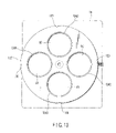
- FIG. 12 schematically shows a cross section in the X direction of a primary part of a transmission illumination apparatus according to a third embodiment of the present invention.
- FIG. 13 is a top view of a turret depicted in FIG. 12 .
- members denoted by the same reference numerals as those of the members shown in FIG. 1 are like members, thereby eliminating their detailed explanation.
- the transmission illumination apparatus comprises four light orientation members 9 A, 9 B, 9 C and 9 D, and a switching mechanism that selectively arranges one of the four light orientation members 9 A, 9 B, 9 C and 9 D between the glass plate 7 and the surface light source 10 .
- This switching mechanism includes a turret 121 that is rotatably supported with respect to the base portion 1 a by a shaft 122 .
- a spacer 123 that restricts the backlash at the time of rotation of the turret 121 is provided between the turret 121 and the base portion 1 a .
- the turret 121 is provided with, e.g., four hole portions 124 A, 124 B, 124 C and 124 D.
- Frames 125 A, 125 B, 125 C and 125 D holding the light orientation members 9 A, 9 B, 9 C and 9 D are respectively placed deep inside and held in the hole portions 124 A, 124 B, 124 C and 124 D.
- the turret 121 can be subjected to the rotation operation by manipulating an operation portion 126 protruding from the base portion 1 a .
- the base portion 1 a is provided with a plunger 127 .
- the plunger 127 has a ball 128 and a spring 129 that are built therein, and the ball 128 is pressed against an outer peripheral surface of the turret 121 by the spring 129 .
- the turret 121 has a click groove 130 on the outer peripheral surface thereof, and rotation of the turret 121 is restricted when the ball 128 falls in the click groove 130 .
- one of the four light orientation members 9 A, 9 B, 9 C and 9 D is appropriately arranged between the glass plate 7 and the surface light source 10 .
- the turret 121 rotates.
- another light orientation member reaches the position between the glass plate 7 and the surface light source 10 , the ball 128 again falls in the click groove 130 , and rotation of the turret 121 is restricted.
- each of the light orientation members 9 A and 9 C comprises a louver film shown in FIG. 2 , and the louver film 9 A is arranged in parallel to the glass plate 7 whilst the louver film 9 C is arranged at a slant with respect to the glass plate 7 as shown in FIG. 12 .
- the louver film 9 A is arranged between the glass plate 7 and the surface light source 10 , an appropriate shadow can be provided to images of the sample 8 , thereby enabling observation.
- the light orientation members 9 B and 9 D may comprise the same louver film as that of the light orientation members 9 A and 9 C and may be obliquely arranged with respect to the glass plate 7 at an angle different from that of the louver film 9 C. By doing so, different oblique illumination can be performed by using each of the louver films 9 B and 9 C, and observation is enabled with the shadows having different intensities being provided to images of the sample 8 .
- the light orientation members 9 A, 9 B, 9 C and 9 D do not have to be arranged in all of the hole portions 124 A, 124 B, 124 C and 124 D, and appropriate hole portions may be used as vacant holes. By doing so, observation without shadows by the louver film 9 can be switched to/from observation with shadows by the louver film 9 .
- the light orientation members 9 A, 9 B, 9 C and 9 D may have the configuration mentioned herein as well as the same configurations as those of the first modification to the third modification of the first embodiment, respectively. With this arrangement, the louver films having various optical characteristics can be switched and utilized, more various kinds of illumination can be effected.
- the light orientation members 9 A, 9 B, 9 C and 9 D having different optical characteristics can be switched and used, the optimum illumination can be performed with respect to various kinds of samples 8 in a transmission illumination apparatus.
- the turret 121 is provided with the four hole portions 124 A, 124 B, 124 C and 124 D in this embodiment, the number of the hole portions can be arbitrarily increased by enlarging the turret 121 , and the number of the hole portions can be also reduced.
- FIG. 14 is a schematic view showing a schematic configuration of an illumination apparatus according to the fourth embodiment and a stereoscopic microscope having this illumination apparatus mounted therein.
- the stereoscopic microscope shown in FIG. 14 comprises a transmission illumination stand 201 as a microscope stand.
- the transmission illumination stand 201 comprises a base portion 201 a that is horizontally arranged and a support column portion 201 b provided upright on the base portion 201 a .
- a sighting device 202 is inserted into and attached to the support column portion 201 b , and moves up and down a movable portion 202 b along a fixed portion 202 a by a non-illustrated built-in sighting mechanism in accordance with an operation of a sighting handle 212 provided at a side surface portion of the movable portion 202 b .
- the zoom mirror body 203 drives the inner lens system in accordance with an operation of a zoom handle 213 provided at the side surface portion, thereby changing an image formation magnification for an image of the sample 208 .
- the binocular tube 205 comprises an eyepiece lens 206 , and a microscopic examiner can observe the sample 208 through the eyepiece lens 206 .
- the base portion 201 a has an opening portion 201 aa at an upper surface portion facing the objective lens 204 , and a glass plate 207 as a transparent sample mount plate on which the sample 208 is mounted is fitted in the opening portion 201 aa .
- a surface light source 212 , a light shielding plate 210 and a cylindrical mirror 211 which constitute the illumination apparatus according to the fourth embodiment, are arranged below the glass plate 207 in the base portion 201 a .
- the discoid surface light source 212 is arranged on the inner surface of the bottom portion of the transmission illumination stand 201 , and the discoid light shielding plate 210 is arranged at an upper surface portion of a transparent resin plate 209 supported by a support portion 201 ac formed in the base portion 201 a .
- the cylindrical mirror 211 having a cylindrical shape is fitted in a cylindrical hole portion 201 ab in the base portion 201 a .
- the surface light source 212 is arranged in such a manner that the optical axis OA is matched with an optical axis as a central axis of the objective lens 204 . Furthermore, the light shielding plate 210 is arranged in such a manner that a central line connecting the centers of the upper and lower surfaces is matched with the optical axis OA, and the cylindrical mirror 211 is arranged in such a manner that a central axis parallel to the cylindrical surface is matched with the optical axis OA.
- FIG. 15 is a plan view showing the surface light source 212 , the light shielding plate 210 , the cylindrical mirror 211 and the resin plate 209 .
- each drawing to which reference is made shows XY coordinate axes that are set with respect to the illumination apparatus or the like according to the present invention for the convenience's sake.
- a direction vertical to the page space corresponding to the right-and-left direction of a microscopic examiner is determined as an X axis
- the right-and-left direction in the page space corresponding to the front-and-back direction of the microscopic examiner is determined as a Y axis.
- the surface light source 212 is realized by using a fluorescent lamp, an LED or the like, receives a power from a power supply portion 212 b connected with a commercial power source, and projects from each point on a light projection surface 212 a a white light with the uniform brightness substantially symmetrically with the optical axis OA at the center. Incidentally, it is good enough for the surface light source 212 to project a white light with a projection angle in a predetermined range that is substantially rotation-symmetrical and oblique with respect to at least the optical axis OA.
- a surface light source 212 it is possible to use, e.g., a surface light source that projects light into a space between two circular cones with different apex angles that are arranged with their central axes being substantially parallel to the optical axis OA, wherein a point on the light projection surface 212 a is determined as a common apex, but does not project light in substantially the same direction as the optical axis OA at each point on the light projection surface 212 a .
- the surface light source 212 may project light that is oblique in one direction with respect to the optical axis OA and the surface light source 212 may be rotated about the optical axis OA.
- the shape of the surface light source 212 is not restricted to a discoid shape, and it may be a hollow discoid shape, a rectangular tabular shape or the like. Additionally, light projected from the surface light source 212 is not restricted to a white light, and the surface light source 212 may project a chromatic light of, e.g., red, green or blue.
- the light shielding plate 210 which is a plate that is formed of opaque material for light projected from the surface light source 212 , shields a part of the light projected from the surface light source 212 .
- the light shielding plate 210 shields light that is directly applied to the sample 8 from the surface light source 212 , and also shields light that is transmitted through the glass plate 207 from the surface light source 212 and directly enters the objective lens 204 .
- the light shielding plate 210 is not restricted to the plate, and it may be a sheet, a film or the like.
- the light shielding plate 210 does not have to be optically completely opaque, and it may transmit light from the surface light source 212 with a predetermined transmission factor like a concentration filter, and it may have a transmission factor distribution in a transmission surface thereof.
- the shape of the upper and lower surfaces as light shielding surfaces of the light shielding plate 210 is not restricted to a circular shape, and it may be an arbitrary shape such as an elliptical shape or a rectangular shape in accordance with applications. That is, the light shielding plate 210 shield light different quantities in two directions perpendicular to each other in a plane vertical to the optical axis.
- the cylindrical mirror 211 which is a reflection illumination member, reflects a part of light projected from the surface light source 212 by a reflection surface 211 a formed on its inner surface to illuminate the sample 208 .
- the reflection surface 211 a is not restricted to a cylindrical surface, and it may be, e.g., a frustum surface having a small apex angle slightly inclined with respect to the optical axis OA.
- the reflection surface 211 a is not restricted to the uniform curved surface, and it may be a surface entirely subjected to patterned indentation processing so that a reflected light can be diverged, converged or diffused.
- an outer shape of the cylindrical mirror 211 is not restricted to the cylindrical shape, and it may be an arbitrary shape such as a square column shape.
- FIG. 16 is a cross-sectional view in the Y direction showing an illumination state with respect to the sample 208 .
- projected light IL 1 - 1 and IL 1 - 2 having large projection angles with the optical axis OA as a reference are reflected by the reflection surface 211 a and illuminate the sample 208 .
- projected light in a range sandwiched by the projected light IL 1 - 1 and IL 1 - 2 also illuminate the sample 208 .
- a projected light IL 2 with a small projection angle projected to be directly applied to the sample 208 is shielded by the light shielding plate 210 .
- the light projected with a large projection angle in a predetermined range is reflected by the reflection surface 211 a and illuminates the sample 208 as illumination light, and the light projected with a small projection angle to be directly applied to the sample 208 is shielded by the light shielding plate 210 .
- FIG. 16 shows this state in the cross section along the Y direction, but this state is actually generated rotation-symmetrically with the optical axis OA as a central axis.
- the illumination light that illuminates the sample 208 is used to illuminate the sample 208 with a larger incidence angle than an angle corresponding to a numerical aperture of the objective lens 204 , which receives light from the sample 208 .
- this illumination apparatus can perform dark field illumination by which illumination is performed with an oblique light that does not directly enter the objective lens 204 , and provide the shadow to the transparent sample 208 .
- the objective lens 204 receives a scattered light and a diffracted light alone generated in the sample 208 as light that is used to observe the sample 208 .
- reflected light that is indicated as projected light IL 3 in FIG. 6 directly illuminates the sample 208 , the illumination efficiency is good.
- a size of the light projection surface 212 a is larger than that of the light shielding plate 210 .
- a short axis of the ellipse is parallel to the X direction and light from the surface light source 212 is directly applied to the sample 208 to some extent so that the shadow generated in the X direction of the sample 208 can be weakened.
- the shadow generated in the X direction of the sample 208 can be weakened by using a concentration filter as the light shielding plate 210 , providing a transmission factor distribution at least in the X direction in the light shielding surface and increasing a light quantity with an increased high transmission factor of light that directly illuminates the sample 208 from the X direction.
- these light shielding plates 210 may be arbitrarily rotatable about the optical axis OA so that the shadow generated to the sample 208 can be changed about the optical axis OA.
- the illumination apparatus of the light projected from the surface light source 212 , the light projected with a large projection angle in a predetermined range is reflected by the reflection surface 211 a to illuminate the sample 208 , and the light projected with a small projection angle to be directly applied to the sample 208 is shielded by the light shielding plate 210 . Therefore, dark field illumination can be performed with respect to the sample 208 with the simple configuration, and the shadow can be provided to the transparent sample 208 . Additionally, the shadow in the X direction can be alleviated by forming the light shielding surface of the light shielding plate 210 into an elliptical shape or providing a transmission factor distribution while using a concentration filter as the light shielding plate 210 . Further, the shadow can be changed about the optical axis OA in many ways by rotating these light shielding plates 210 .
- a fifth embodiment according to the present invention will now be described. Although the light projected from the surface light source 212 with a small projection angle to be directly applied to the sample 208 is shielded by the light shielding plate 210 in the fourth embodiment described above, a light orientation member is used in place of the light shielding plate 210 and light that is directly applied to the sample 208 is shielded in the fifth embodiment.
- FIG. 17 is a schematic view showing a configuration of an illumination apparatus and a part of a configuration of a stereoscopic microscope according to the fifth embodiment of the present invention.
- the illumination apparatus according to the fifth embodiment comprises a light orientation member 213 in place of the light shielding plate 210 and the resin plate 209 provided in the illumination apparatus according to the fourth embodiment. Any other configurations are the same as the fourth embodiment, and like reference numerals denote like constituent parts.
- the light orientation member 213 is realized by a louver film.
- FIG. 18A is a perspective view schematically showing a part of a configuration of the louver film, which is the light orientation member 213 .
- the light orientation member 213 is formed of strip-like opaque members 213 a arranged in a louver shape and a transparent holding member 213 b that holds the opaque members 213 a .
- the opaque members 213 a are opaque with respect to light projected from the surface light source 212
- the transparent holding member 213 b is transparent with respect to this light.
- the opaque members 213 a are entirely inclined with respect to upper and lower surfaces of the tabular transparent holding member 213 b.
- FIG. 18B is a cross-sectional view schematically showing a state of illumination light when the light orientation member 213 is illuminated by using the surface light source 212 .
- FIG. 18B in the Y-direction cross section perpendicular to the longitudinal direction of the opaque members 213 a , of light projected from a point P 2 on the light projection surface 212 , projected light IL 4 - 2 and IL 4 - 3 passing through each gap between the respective opaque members 213 a are transmitted through the light orientation member 213 , and projected light IL 4 - 4 and IL 4 - 5 crossing the opaque members 213 a are shielded by the light orientation member 213 .
- the projected light IL 4 - 2 is a projected light having the largest projection angle in the projected light that can be transmitted through the light orientation member 213
- the projected light IL 4 - 3 is a projected light having the smallest projection angle.
- all the projected light projected from the light projection surface 212 a are transmitted through the light orientation member 213 in a cross section parallel to the longitudinal direction of each opaque member 213 a and substantially parallel to the surface of each opaque member 213 a
- an arbitrary projected light projected from the light projection surface 212 a is shielded by the light orientation member 213 in a cross section crossing the surface of each opaque member 213 a .
- the projected light that includes each of the projected light IL 4 - 2 and IL 4 - 3 and is projected into a space sandwiched between two planes parallel to the X axis is transmitted through the light orientation member 213 , and any other projected light is shielded by the light orientation member 213 .
- the projection angles of the projected light IL 4 - 2 and IL 4 - 3 can be adjusted by changing at least one of each gap between the respective opaque members 213 a and the inclination angle of these members 213 a .
- the projected light IL 4 - 3 that vertically enters the light orientation member 213 can be transmitted by increasing each gap between the respective opaque members 213 a.
- the light orientation member 213 is entirely formed into a circular shape, and the opaque members 213 a are concentrically formed with the center of a discoid as a reference.
- FIG. 19 is a plan view showing the cylindrical mirror 211 and the light orientation member 213 .
- the light orientation member 213 is arranged so that the optical axis OA runs through the center of the concentric circles of the opaque members 213 a .
- each opaque member 213 a is rotation-symmetrically inclined with respect to the optical axis OA so that an inward normal line forms an elevation angle. That is, the light orientation member 213 has opaque members 213 a having similar hollow truncated circular cone shapes whose bottom circles are concentrically arranged.
- FIG. 20 is a cross section in the Y direction showing an illumination state with respect to the sample 208 .
- projected light IL 1 - 1 and IL 1 - 2 having large projection angles are reflected by the reflection surface 211 a to illuminate the sample 208 and, likewise, projected light in a range sandwiched between the projected light IL 1 - 1 and IL 1 - 2 also illuminate the sample 208 .
- a projected light IL 2 with a small projection angle projected to be directly applied to the sample 208 is shielded by the light orientation member 213 .
- FIG. 20 shows this state in the cross section along the Y direction, this state is actually generated rotation-symmetrically with the optical axis OA as a central axis.
- illumination light that illuminates the sample 208 illuminates the sample 208 with an incidence angle larger than an angle corresponding to a numerical aperture of the objective lens 204 .
- dark field illumination can be likewise performed with respect to the sample 208 , and the shadow can be provided to the transparent sample 208 .
- the projected light IL 3 that directly enters the objective lens 204 in the illumination apparatus described in conjunction with the fourth embodiment can be shielded by the light orientation member 213 , thereby realizing perfect dark field illumination.
- each gap between the respective opaque members 213 a in the X direction may be increased so that an angle range in which illumination light falls on the sample 208 can be increased, and that the gap may be further increased so that the light from the surface light source 212 can be directly applied to the sample 208 to some extent, for example.
- the light orientation member 213 having such a configuration may be arbitrarily rotatable about the optical axis OA so that the shadow generated to the sample 208 can be changed about the optical axis OA.
- a light orientation member 213 ′ in which each gap between respective opaque members 213 a is increased may be used so that a light quantity of illumination light with respect to the sample 208 can be increased.
- the light shielding plate 210 since light having a small projection angle from the surface light source 212 is transmitted through each gap between the respective opaque members 213 a to directly illuminate the sample 208 , it is desirable to arrange the light shielding plate 210 on the upper surface portion of the light orientation member 213 ′ in order to shield the light used for direct illumination.
- a light orientation member 214 having opaque members 214 a that have similar hexagonal shapes having different sizes in an XY plane and are arranged with their gravity points being coincided with each other may be used in place of the light orientation member 213 having the opaque members 213 a that are concentrically arranged.
- the light orientation member 214 having a discoid shape as a whole may be formed by bonding side surfaces of the light orientation members 214 - 1 to 214 - 6 each corresponding to each side of the hexagon and having a fan plate shape.
- each opaque member 214 formed into a hexagonal shape is inclined with respect to the optical axis OA in such a manner that inner normal lines form equal elevation angles.
- the light orientation member 214 has the opaque members 214 having similar truncated pyramid shapes in which polygons of the bottom surfaces are arranged with their gravity points being overlapped. Furthermore, each gap between the respective opaque members 214 a is reduced in size so that light having a small projection angle that directly illuminates the sample 208 is not generated from the surface light source 212 .
- dark field illumination can be performed with respect to the sample 208 and the shadow can be provided to the transparent sample 208 like the light orientation member 213 .
- the light orientation member 214 ′ in which each gap between the respective opaque members 214 a is increased is used to increase a light quantity of illumination light with respect to the sample 208 , it is good enough to arrange the light shielding plate 210 on the upper surface portion of the light orientation member 214 ′ so that the light that directly illuminates the sample 208 can be shielded, as shown in FIG. 23 .
- the arrangement shape of the opaque members in the XY plane is the hexagonal shape in the light orientation members 214 and 214 ′, the present invention is not restricted thereto, and any arbitrary polygonal shape can be used.
- the illumination apparatus of the light projected from the surface light source 212 , the light projected with a large projection angle in a predetermined range is reflected by the reflection surface 211 a so that the sample 208 is illuminated with this light, and the light projected with a small projection angle that directly illuminates the sample 208 is shielded by the light orientation members 213 and 214 , and hence dark field illumination can be effected for the sample 208 by using the simple structure, and the shadow can be provided to the transparent sample 208 . Additionally, in this illumination apparatus, since the light that directly enters the objective lens 204 from the surface light source 212 is shielded by the light orientation member 213 , perfect dark field illumination can be realized.
- dark field illumination can be carried out by further providing the light shielding plate 210 on the upper surface portions of the light orientation members 213 and 214 .
- a sixth embodiment according to the present invention will now be described.
- the light orientation member 213 in which the opaque members 213 a are rotation-symmetrically arranged is used in order to perform dark field illumination with respect to all directions of the sample 208 in the fifth embodiment
- a light orientation member in which opaque members are arranged in a louver form is used so that dark field illumination is effected with respect to a predetermined direction of the sample 208 and this direction can be arbitrarily changed in the sixth embodiment.
- FIG. 24 is a schematic view showing a configuration of an illumination apparatus and a partial configuration of a stereoscopic microscope according to the sixth embodiment of the present invention.
- the illumination apparatus according to the sixth embodiment comprises a light orientation member 215 in place of the light orientation member 213 included in the illumination apparatus according to the fifth embodiment, and further comprises a light shielding plate 210 on an upper surface portion of the light orientation member 215 . Additionally, this illumination apparatus newly comprise a rotation drive portion 216 .
- the cylindrical rotation drive portion 216 is arranged in such a manner that it is fitted in an inner cylindrical hole portion 201 ab of the base portion 201 a , holds the light orientation member 215 in the cylinder thereof, and rotates the light orientation member 215 and the light shielding plate 210 about the optical axis OA in accordance with an operation by a microscopic examiner. It is to be noted that the rotation drive portion 216 is supported by a lid member 217 so that it does not fall off the hole portion 201 ab . Any other configuration is the same as the fifth embodiment, and like reference numerals denote like constituent parts.
- FIG. 25 is a plan view showing the light orientation member 215 , the light shielding plate 210 , the rotation drive portion 216 and an operation mechanism that drives the rotation drive portion 216 .
- a rotary shaft 218 and a discoid rotation knob 219 capable of rotating about the rotary shaft 218 are provided at a position in the X direction from the optical axis OA at an upper surface end portion of the base portion 201 a .
- a gear 219 a subjected to knurling processing is provided on an outer peripheral side surface of the rotation knob 219 , and rotation of the gear 219 a is transmitted to the rotation drive portion 216 when an outer peripheral side surface of the rotation drive portion 216 , which is likewise subjected knurling processing, is brought into contact with the gear 219 a and their knurled portions are meshed with each other.
- the rotation knob 219 and a part of the outer peripheral portion of the gear 219 a protrude from the side surface portion of the base portion 201 a , and a microscopic examiner can rotate the light orientation member 215 and the light shielding plate 210 together with the rotation drive portion 216 about the optical axis OA by rotating the protruding portions about the rotary shaft 218 .
- the rotation drive portion 216 is manually rotated by using the gear 219 a in this embodiment, a drive mechanism such as a stepping motor, a voice coil motor, a piezoelectric element may be further provided in order to automatically drive the gear 219 a , or the rotation drive portion 216 may be directly automatically driven.
- FIG. 26 is a perspective view schematically showing a partial configuration of a louver film as the light orientation member 215 .
- the light orientation member 215 comprises opaque members 215 a arranged in a louver form and a transparent holding member 215 b that holds the opaque members 215 a .
- the opaque members 215 a are entirely vertically arranged with respect to upper and lower surfaces of the tabular transparent holding member 215 b . It is to be noted that the opaque members 215 a are uniformly arranged on the entire surface in the light orientation member 215 .
- FIGS. 27A and 27B are cross-sectional views showing illumination states with respect to the sample 208 , and show a cross section in the Y direction and a cross section in the X direction in accordance with a state of the light orientation member 215 depicted in FIG. 25 , respectively. As shown in FIG.
- the illumination light that is used to illuminate the sample 208 illuminates the sample 208 at an incidence angle larger than an angle corresponding to a numerical aperture of the objective lens 204 .
- dark field illumination can be likewise performed with respect to the sample 208 , and the shadow can be provided to the transparent sample 208 .
- dark field illumination can be effected in the cross section parallel to the opaque members 215 a , but the sample 208 cannot be illuminated in the cross section crossing the opaque members 215 a , thereby carrying out dark field illumination with respect to a predetermined direction of the sample 208 only.
- the light orientation member 215 can be rotated about the optical axis OA, a direction along which dark field illumination is carried out can be arbitrarily set with respect to the sample 208 .
- FIGS. 28A and 28B are cross-sectional views showing illumination states with respect to the sample 208 .
- the illumination apparatus depicted in FIGS. 28A and 28B has a configuration in which the light shielding plate 210 and the cylindrical mirror 211 are removed from the illumination apparatus according to the sixth embodiment shown in FIG. 24 . In this case, as shown in FIG.
- the shadow is apt to be generated since an incidence angle of the light that is applied to the sample 208 is restricted in the cross section perpendicular to the opaque members 215 a , and the shadow is hard to be generated in the cross section parallel to the opaque members 215 a since the light having various incidence angles are applied to the sample 208 . Therefore, a direction in which the shadow is provided to the sample 208 can be changed by rotating the light orientation member 215 about the optical axis OA by the rotation drive portion 216 , and a microscopic examiner can observe the sample 208 with respect to the shadow in an arbitrary direction.
- the shadow of the sample 208 may be emphasized by using a light orientation member 220 in which the opaque members 215 a have a different inclination angle in place of the light orientation member 215 .
- the light orientation member 220 is held in a state where opaque members 220 a are inclined with respect to upper and lower surfaces of a transparent holding member 220 b like the light orientation member 213 shown in FIG. 18A .
- oblique illumination in which all of light are oblique with respect to the optical axis OA can be performed for the sample 208 , as shown in FIG. 29 .
- FIG. 29 For example, in FIG.
- the shadow on the right-hand side of the sample 208 can be emphasized by this oblique illumination.
- a direction of the shadow to be emphasized can be changed by rotating the light orientation member 220 about the optical axis OA by using the rotation drive mechanism 216 , and a microscopic examiner can observe the sample 208 having the shadow emphasized in an arbitrary direction.
- the intensity of the shadow produced to the sample 208 can be adjusted by changing each gap between the respective opaque members 215 a and 220 a in the light orientation members 215 and 220 .
- the shadow can be intensified by reducing each gap whilst the shadow can be weakened by increasing each gap.
- the light orientation members may be arranged in a layer form along the optical axis OA as shown in FIG. 30 , for example.
- the light orientation member 215 is further arranged above the light shielding plate 210 and fitted and fixed in the hole portion 201 ad in the base portion 201 a in the structure of the illumination apparatus according to the sixth embodiment.
- the upper light orientation member 215 is fixed with the opaque members 215 a being parallel to the X direction.
- FIGS. 31A and 31B are plan views showing relationships of the upper and lower light orientation members 215 .
- FIG. 31A shows a case where the upper and lower opaque members 215 a are parallel to each other
- FIG. 31B shows a case where the upper and lower opaque members 215 a are perpendicular to each other.
- FIG. 31A when directions of the upper and lower opaque members are matched with each other in the X direction, dark field illumination can be performed with respect to the sample 208 in the X direction.
- FIG. 31A shows a case where the upper and lower opaque members 215 a are parallel to each other
- FIG. 31B shows a case where the upper and lower opaque members 215 a are perpendicular to each other.
- the two light orientation members 215 are used and one of these members can be rotated about the optical axis OA in this embodiment, but a light orientation member having a different gap, inclination and the like of the opaque members may be used, three or more such light orientation members may be used, and the light orientation members may be rotated about the optical axis OA.
- the illumination state with respect to the sample 208 can be adjusted in many ways, for example, a direction in which dark field illumination is performed or a state of the shadow can be adjusted.
- the light orientation members arranged in a layer form along the optical axis OA can be applied to the illumination apparatus for the purpose of adjusting a state of the shadow of the sample 208 or a light quantity of the illumination light aside from dark field illumination.
- the illumination apparatus for example, as shown in FIG. 32 , there is adopted a structure in which the light shielding plate 210 and the cylindrical mirror 211 are removed and two light orientation members 215 are arranged along the optical axis OA, and the lower light drive member 215 is rotated by the rotation drive portion 216 .
- directions of the upper and lower opaque members 215 a can be relatively changed, a light quantity that is used to illuminate the sample 208 can be adjusted, and a state of the shadow with respect to the sample 208 can be adjusted.
- a light orientation member having a different gap, inclination and the like of the opaque members may be used, three or more such light orientation members may be used, and the light orientation members may be rotated about the optical axis OA.
- a seventh embodiment according to the present invention will now be described. Although a set of the light orientation member, the light shielding plate and the cylindrical mirror is provided in the base portion 201 a in the fourth to sixth embodiments, combinations of the light orientation member, the light shielding plate, the cylindrical mirror or the like are provided in the base portion and can be arbitrarily switched in the seventh embodiment.
- FIG. 33 is a schematic view showing a configuration of an illumination apparatus and a partial configuration of a stereoscopic microscope according to the seventh embodiment of the present invention.
- the stereoscopic microscope according to the seventh embodiment comprises a base portion 201 c in place of the base portion 201 a included in the stereoscopic microscope according to the fourth embodiment to the sixth embodiment, and a switching mechanism capable of switching combinations of the light orientation member, the light shielding plate, the cylindrical mirror and the like is provided in the base portion 201 c .
- This switching mechanism is roughly configured to have two stages, i.e., upper and lower stages, and the upper switching mechanism has a turret 232 , a rotary shaft 233 , a spacer 234 and a plunger 236 , whilst the lower switching mechanism likewise has a turret 242 , a rotary shaft 243 , a spacer 244 and a plunger 246 .
- the base portion 201 c and the switching mechanism is the same as those in the fourth embodiment to the sixth embodiment, and like reference numerals denote like constituent parts.
- FIG. 34 is a plan view showing the upper switching mechanism.
- the turret 232 is supported by the base portion 201 c in such a manner that the turret 232 can rotate about the rotary shaft 233 .
- the spacer 232 is provided between the base portion 201 c and the turret 232 so that the backlash when the turret 232 rotates is restricted.
- the turret 232 has four circular opening portions 232 a to 232 d , and light adjustment members 231 A to 231 D respectively slotted in cylindrical frames 235 A to 235 D are held in the opening portions 232 a to 232 d .
- the plunger 236 has a ball 237 and a spring 238 , and is provided at a position facing the turret 232 at a side surface portion of the base portion 201 c.
- the turret 232 has four click grooves 239 A to 239 D at a outer peripheral side portion provided on lines connecting the rotary shaft 233 with the respective opening portions 232 a to 232 d and, when the ball 237 partially pushed out by a stretching force of the spring 238 falls in one of the click grooves 239 A to 239 D, rotation with respect to the base portion 201 c is restricted and one of the light adjustment members 231 A to 231 D is arranged between the sample 208 and the surface light source 212 .
- the light adjustment member 231 A is arranged between the sample 208 and the surface light source 212 .
- the upper switching mechanism can selectively arrange one of the light adjustment members 231 A to 231 D on the optical axis OA.
- a microscopic examiner can rotate the turret 232 by operating a portion protruding from the base portion 201 c of the turret 232 .
- the light adjustment members 231 A to 231 D arranged between the sample 208 and the surface light source 212 can be rotated about the optical axis OA by using a non-illustrated rotation drive mechanism.
- the lower switching mechanism is configured like the upper switching mechanism.
- the turret 242 is supported by the base portion 201 c in such a manner that the turret 242 can rotate about the rotary shaft 243 by the rotary shaft 243 , and the spacer 242 is provided so that the backlash when the turret 242 rotates is restricted.
- the turret 242 has four circular opening portions 242 a to 242 d , and light adjustment members 241 A to 241 D respectively slotted in cylindrical frames 245 A to 245 D are held in the opening portions 242 a to 242 d .
- the plunger 246 has a ball 247 and a spring 248 , and is provided at a position facing the turret 242 at the side surface portion of the base portion 201 c .
- the turret 242 has four click groove 249 A to 249 D at the outer peripheral side surface portion and, when the ball 247 falls in one of the click grooves 249 A to 249 D, rotation with respect to the base portion 201 c is restricted, and one of the light adjustment members 214 A to 241 D is arranged between the sample 208 and the surface light source 212 . That is, the lower switching mechanism can selectively arrange one of the light adjustment members 241 A to 241 D on the optical axis OA.
- a microscopic examiner can rotate the turret 242 by operating a portion protruding from the base portion 201 c of the turret 242 .
- the light adjustment members 214 A to 241 D arranged between the sample 208 and the surface light source 212 can be rotated about the optical axis OA by a non-illustrated rotation drive mechanism.
- arbitrary one of the light adjustment members 241 A to 241 D can be combined with each of the light adjustment members 231 A to 231 D so that the light adjustment members can be arranged in a layer form between the sample 208 and the surface light source 212 along the optical axis OA.
- the light orientation members 213 , 214 , 215 and 220 , the resin plate 209 and the like described in conjunction with the fourth embodiment to the sixth embodiment can be applied to the light adjustment members 231 A to 231 D and 241 A to 241 D.
- a light shielding plate 231 Ba may be provided in accordance with the light shielding plate 210 as shown in FIG. 34 , for example. Further, inner surfaces of the cylindrical frames 235 A to 235 D and 245 A to 245 D may be determined as reflection surfaces in accordance with the cylindrical mirror 211 . Furthermore, various kinds of filters such as a concentration filter, a color temperature filter, a wavelength selection filter, a polarization filter or the like may be applied as the light adjustment members 231 A to 231 D and 241 A to 241 D, or no member may be arranged to keep a vacant hole state.
- a microscopic examiner can perform various kinds of illumination such as dark field illumination, bright field illumination or oblique illumination with respect to the sample 208 and adjust a state of the shadow produced to the sample 208 , a light quantity that is used to illuminate the sample 208 and the like in many ways by using various combinations of these members.
- the directionality such as a direction in which illumination is effected or a direction in which the shadow is produced can be provided, and this direction can be rotated about the optical axis OA.
- the turrets 232 and 242 respectively hold the four light adjustment members 231 A to 231 D and 241 A to 241 D, but they may hold two, three, five or more light adjustment members.
- the base portion 201 c comprises the switching mechanism having the two stages, i.e., the upper and lower stages, but it may comprise a switching mechanism having three or more stages.
- the turrets 232 and 242 are used as this switching mechanism and the light adjustment members are switching by rotation driving, but the light adjustment members may be switched in a linear sliding manner. Further, these switching mechanisms may be automatically driven.
- the illumination apparatus according to the present invention is mounted in a binocular stereoscopic microscope in the first embodiment to the seventh embodiment, the illumination apparatus may be mounted in a monocular microscope, or it may be mounted in various kinds of optical microscope irrespective of applications of a biological microscope, an industrial microscope or the like.
Abstract
Description
L<0.7D
A<0.9 tan−1(D/2L),
so that the shadow is provided to the
L<0.7D
represents that the distance between the sample mount surface and the
A<0.9 tan−1(D/2L).
Claims (4)
L<0.7D
A<0.9 tan−1(D/2L).
Priority Applications (1)
| Application Number | Priority Date | Filing Date | Title |
|---|---|---|---|
| US11/971,833 US7554727B2 (en) | 2004-04-28 | 2008-01-09 | Illumination apparatus for microscope |
Applications Claiming Priority (6)
| Application Number | Priority Date | Filing Date | Title |
|---|---|---|---|
| JP2004-134375 | 2004-04-28 | ||
| JP2004134375A JP4678818B2 (en) | 2004-04-28 | 2004-04-28 | Microscope transmitted illumination device |
| JP2004-359111 | 2004-12-10 | ||
| JP2004359111A JP2006171025A (en) | 2004-12-10 | 2004-12-10 | Illumination apparatus |
| US11/113,381 US7345815B2 (en) | 2004-04-28 | 2005-04-22 | Illumination apparatus for microscope |
| US11/971,833 US7554727B2 (en) | 2004-04-28 | 2008-01-09 | Illumination apparatus for microscope |
Related Parent Applications (1)
| Application Number | Title | Priority Date | Filing Date |
|---|---|---|---|
| US11/113,381 Division US7345815B2 (en) | 2004-04-28 | 2005-04-22 | Illumination apparatus for microscope |
Publications (2)
| Publication Number | Publication Date |
|---|---|
| US20080117502A1 US20080117502A1 (en) | 2008-05-22 |
| US7554727B2 true US7554727B2 (en) | 2009-06-30 |
Family
ID=34935678
Family Applications (2)
| Application Number | Title | Priority Date | Filing Date |
|---|---|---|---|
| US11/113,381 Active 2025-10-12 US7345815B2 (en) | 2004-04-28 | 2005-04-22 | Illumination apparatus for microscope |
| US11/971,833 Active US7554727B2 (en) | 2004-04-28 | 2008-01-09 | Illumination apparatus for microscope |
Family Applications Before (1)
| Application Number | Title | Priority Date | Filing Date |
|---|---|---|---|
| US11/113,381 Active 2025-10-12 US7345815B2 (en) | 2004-04-28 | 2005-04-22 | Illumination apparatus for microscope |
Country Status (2)
| Country | Link |
|---|---|
| US (2) | US7345815B2 (en) |
| EP (2) | EP2256536B1 (en) |
Cited By (5)
| Publication number | Priority date | Publication date | Assignee | Title |
|---|---|---|---|---|
| DE102011003569A1 (en) | 2011-02-03 | 2012-08-09 | Leica Microsystems (Schweiz) Ag | Area light source for a transmitted light illumination device of a microscope |
| DE102011003568A1 (en) | 2011-02-03 | 2012-08-09 | Leica Microsystems (Schweiz) Ag | Area light source for a transmitted light illumination device of a microscope |
| DE102011003603A1 (en) | 2011-02-03 | 2012-08-09 | Leica Microsystems (Schweiz) Ag | Transmitted light illumination device for a microscope |
| DE102013206725A1 (en) | 2013-04-15 | 2014-10-16 | Leica Microsystems (Schweiz) Ag | Microscope illumination device for directional microscope illumination |
| EP3364226A1 (en) | 2017-02-16 | 2018-08-22 | Leica Instruments (Singapore) Pte. Ltd. | Transmitted light illumination apparatus for a microscope |
Families Citing this family (14)
| Publication number | Priority date | Publication date | Assignee | Title |
|---|---|---|---|---|
| CN101371190B (en) * | 2006-01-20 | 2010-10-13 | 日本电气株式会社 | Mobile terminal |
| JP2008096895A (en) * | 2006-10-16 | 2008-04-24 | Olympus Corp | Illuminator for microscope |
| US8199262B2 (en) * | 2007-01-04 | 2012-06-12 | Honeywell International Inc. | Filter frame and display head assembly |
| EP2128677A4 (en) * | 2007-03-22 | 2012-03-07 | Altair Corp | Microscope |
| WO2009136578A1 (en) * | 2008-05-09 | 2009-11-12 | パイオニア株式会社 | Spatial image display apparatus |
| WO2011004714A1 (en) * | 2009-07-06 | 2011-01-13 | 株式会社ニコン | Microscope |
| DE102011114377A1 (en) | 2011-09-23 | 2013-03-28 | Carl Zeiss Microscopy Gmbh | Apparatus and method for transmitted light illumination for light microscopes and microscope system |
| DE102011114336A1 (en) * | 2011-09-23 | 2013-03-28 | Carl Zeiss Microscopy Gmbh | Apparatus and method for transmitted light illumination for light microscopes and microscope system |
| CN103707280B (en) * | 2013-12-24 | 2016-03-23 | 中国科学院自动化研究所 | A kind of illumination clamper and clamp method being applicable to small printing opacity part |
| EP4030201A1 (en) | 2014-10-14 | 2022-07-20 | Nanotronics Imaging, Inc. | An imaging apparatus and a process for imaging a surface of a specimen |
| EP3040705A1 (en) * | 2014-12-30 | 2016-07-06 | Grundfos Holding A/S | Method for determining of particles |
| CN107436456B (en) * | 2016-05-27 | 2020-12-04 | 上海蓝湖照明科技有限公司 | Diffusion device and manufacturing method thereof, light-emitting device, projection system and illumination system |
| JP2019114503A (en) * | 2017-12-26 | 2019-07-11 | オリンパス株式会社 | Illumination apparatus and microscope apparatus |
| CN113767315A (en) * | 2019-01-18 | 2021-12-07 | Essenlix 公司 | Multi-mode lighting system |
Citations (7)
| Publication number | Priority date | Publication date | Assignee | Title |
|---|---|---|---|---|
| US4221867A (en) | 1979-02-02 | 1980-09-09 | Minnesota Mining And Manufacturing Company | Optical microbiological testing apparatus and method |
| US4659193A (en) | 1983-10-24 | 1987-04-21 | Olympus Optical Co., Ltd. | Epidark illumination device |
| JPH07122694B2 (en) | 1986-10-16 | 1995-12-25 | オリンパス光学工業株式会社 | Illumination device for microscope |
| US6040940A (en) | 1998-02-04 | 2000-03-21 | Olympus Optical Co., Ltd. | Reflecting fluorescence microscope |
| JP3194909B2 (en) | 1991-04-30 | 2001-08-06 | オリンパス光学工業株式会社 | Transmission optical microscope |
| US20020191281A1 (en) | 1997-08-29 | 2002-12-19 | Olympus Optical Co., Ltd. | Microscope transmitted-illumination apparatus |
| EP1469333A1 (en) | 2003-04-15 | 2004-10-20 | Olympus Corporation | Microscope apparatus |
Family Cites Families (1)
| Publication number | Priority date | Publication date | Assignee | Title |
|---|---|---|---|---|
| ATE400832T1 (en) * | 1999-12-23 | 2008-07-15 | Oldfield Sciences Ltd | MICROSCOPE, METHOD FOR PRODUCING A MICROSCOPE AND METHOD FOR OPERATING A MICROSCOPE |
-
2005
- 2005-04-22 US US11/113,381 patent/US7345815B2/en active Active
- 2005-04-25 EP EP10009143.8A patent/EP2256536B1/en not_active Not-in-force
- 2005-04-25 EP EP05009003.4A patent/EP1591821B1/en not_active Not-in-force
-
2008
- 2008-01-09 US US11/971,833 patent/US7554727B2/en active Active
Patent Citations (8)
| Publication number | Priority date | Publication date | Assignee | Title |
|---|---|---|---|---|
| US4221867A (en) | 1979-02-02 | 1980-09-09 | Minnesota Mining And Manufacturing Company | Optical microbiological testing apparatus and method |
| US4659193A (en) | 1983-10-24 | 1987-04-21 | Olympus Optical Co., Ltd. | Epidark illumination device |
| JPH07122694B2 (en) | 1986-10-16 | 1995-12-25 | オリンパス光学工業株式会社 | Illumination device for microscope |
| JP3194909B2 (en) | 1991-04-30 | 2001-08-06 | オリンパス光学工業株式会社 | Transmission optical microscope |
| US20020191281A1 (en) | 1997-08-29 | 2002-12-19 | Olympus Optical Co., Ltd. | Microscope transmitted-illumination apparatus |
| US6040940A (en) | 1998-02-04 | 2000-03-21 | Olympus Optical Co., Ltd. | Reflecting fluorescence microscope |
| EP1469333A1 (en) | 2003-04-15 | 2004-10-20 | Olympus Corporation | Microscope apparatus |
| US20040207915A1 (en) | 2003-04-15 | 2004-10-21 | Olympus Corporation | Microscope apparatus |
Cited By (12)
| Publication number | Priority date | Publication date | Assignee | Title |
|---|---|---|---|---|
| DE102011003569A1 (en) | 2011-02-03 | 2012-08-09 | Leica Microsystems (Schweiz) Ag | Area light source for a transmitted light illumination device of a microscope |
| DE102011003568A1 (en) | 2011-02-03 | 2012-08-09 | Leica Microsystems (Schweiz) Ag | Area light source for a transmitted light illumination device of a microscope |
| DE102011003603A1 (en) | 2011-02-03 | 2012-08-09 | Leica Microsystems (Schweiz) Ag | Transmitted light illumination device for a microscope |
| DE102011003569B4 (en) * | 2011-02-03 | 2013-03-21 | Leica Microsystems (Schweiz) Ag | Area light source for a transmitted light illumination device of a microscope |
| DE102011003568B4 (en) * | 2011-02-03 | 2013-03-21 | Leica Microsystems (Schweiz) Ag | Area light source for a transmitted light illumination device of a microscope |
| US8469572B2 (en) | 2011-02-03 | 2013-06-25 | Leica Microsystems (Schweiz) Ag | Flat panel light source for a transillumination device of a microscope |
| US8534893B2 (en) | 2011-02-03 | 2013-09-17 | Leica Microsystems (Schweiz) Ag | Flat panel light source for a transillumination device of a microscope |
| US8837042B2 (en) | 2011-02-03 | 2014-09-16 | Leica Microsystems (Schweiz) Ag | Transillumination device for a microscope |
| DE102011003603B4 (en) | 2011-02-03 | 2019-12-24 | Leica Microsystems (Schweiz) Ag | Transmitted light illumination device for a microscope |
| DE102013206725A1 (en) | 2013-04-15 | 2014-10-16 | Leica Microsystems (Schweiz) Ag | Microscope illumination device for directional microscope illumination |
| EP3364226A1 (en) | 2017-02-16 | 2018-08-22 | Leica Instruments (Singapore) Pte. Ltd. | Transmitted light illumination apparatus for a microscope |
| US10598913B2 (en) | 2017-02-16 | 2020-03-24 | Leica Instruments (Singapore) Pte. Ltd. | Transmitted light illumination apparatus for a microscope |
Also Published As
| Publication number | Publication date |
|---|---|
| US7345815B2 (en) | 2008-03-18 |
| US20050243413A1 (en) | 2005-11-03 |
| EP1591821A1 (en) | 2005-11-02 |
| EP1591821B1 (en) | 2017-03-01 |
| EP2256536A1 (en) | 2010-12-01 |
| EP2256536B1 (en) | 2018-09-12 |
| US20080117502A1 (en) | 2008-05-22 |
Similar Documents
| Publication | Publication Date | Title |
|---|---|---|
| US7554727B2 (en) | Illumination apparatus for microscope | |
| JP6012184B2 (en) | Microscope transmitted illumination device | |
| WO1999012068A1 (en) | Transmission illuminator for microscopes | |
| US7800821B2 (en) | Microscopic illumination apparatus | |
| US20070211460A1 (en) | Multi-color LED light source for microscope illumination | |
| DE19919096A1 (en) | Transmitted light illumination device for microscopes | |
| US6963445B2 (en) | Light diffuser for optical microscopes replacing condenser with opal glass to produce near-koehler illumination | |
| US7576911B1 (en) | Variable aperture transmissive substage microscope illuminator | |
| JP4695930B2 (en) | Magnification imaging device | |
| US9042011B2 (en) | Microscope having a transmitted-light illuminating device for critical illumination | |
| JP2001188176A (en) | Stereoscopic microscope and transmission lighting device | |
| EP2758812B1 (en) | Transillumination device and method for light microscopes, and a microscope system | |
| EP0547232A1 (en) | Magnifying observation apparatus | |
| US4109999A (en) | Illuminating device for slit lamp microscopes | |
| JP2007017901A (en) | Illumination device and microscope | |
| JP5094950B2 (en) | Microscope transmitted illumination device | |
| JP2006171025A (en) | Illumination apparatus | |
| JP2768470B2 (en) | Stereo microscope | |
| JP4678818B2 (en) | Microscope transmitted illumination device | |
| JP4624543B2 (en) | Microscope illumination system | |
| JP2019040065A (en) | Monitoring camera | |
| JP2004325869A (en) | Microscope | |
| JP2019114503A (en) | Illumination apparatus and microscope apparatus | |
| JP2001188177A (en) | Stereoscopic microscope and dark field lighting device | |
| JP2004325481A (en) | Stereoscopic microscope |
Legal Events
| Date | Code | Title | Description |
|---|---|---|---|
| FEPP | Fee payment procedure |
Free format text: PAYOR NUMBER ASSIGNED (ORIGINAL EVENT CODE: ASPN); ENTITY STATUS OF PATENT OWNER: LARGE ENTITY |
|
| STCF | Information on status: patent grant |
Free format text: PATENTED CASE |
|
| FPAY | Fee payment |
Year of fee payment: 4 |
|
| AS | Assignment |
Owner name: OLYMPUS CORPORATION, JAPAN Free format text: CHANGE OF ADDRESS;ASSIGNOR:OLYMPUS CORPORATION;REEL/FRAME:039344/0502 Effective date: 20160401 |
|
| FPAY | Fee payment |
Year of fee payment: 8 |
|
| MAFP | Maintenance fee payment |
Free format text: PAYMENT OF MAINTENANCE FEE, 12TH YEAR, LARGE ENTITY (ORIGINAL EVENT CODE: M1553); ENTITY STATUS OF PATENT OWNER: LARGE ENTITY Year of fee payment: 12 |
|
| AS | Assignment |
Owner name: EVIDENT CORPORATION, JAPAN Free format text: ASSIGNMENT OF ASSIGNORS INTEREST;ASSIGNOR:OLYMPUS CORPORATION;REEL/FRAME:062492/0267 Effective date: 20221024 |