EP0545052A2 - Dispositif d'illumination et projecteur l'utilisant - Google Patents
Dispositif d'illumination et projecteur l'utilisant Download PDFInfo
- Publication number
- EP0545052A2 EP0545052A2 EP92117925A EP92117925A EP0545052A2 EP 0545052 A2 EP0545052 A2 EP 0545052A2 EP 92117925 A EP92117925 A EP 92117925A EP 92117925 A EP92117925 A EP 92117925A EP 0545052 A2 EP0545052 A2 EP 0545052A2
- Authority
- EP
- European Patent Office
- Prior art keywords
- light
- optical system
- light source
- reflector
- illuminating
- Prior art date
- Legal status (The legal status is an assumption and is not a legal conclusion. Google has not performed a legal analysis and makes no representation as to the accuracy of the status listed.)
- Granted
Links
Images


Classifications
-
- F—MECHANICAL ENGINEERING; LIGHTING; HEATING; WEAPONS; BLASTING
- F21—LIGHTING
- F21V—FUNCTIONAL FEATURES OR DETAILS OF LIGHTING DEVICES OR SYSTEMS THEREOF; STRUCTURAL COMBINATIONS OF LIGHTING DEVICES WITH OTHER ARTICLES, NOT OTHERWISE PROVIDED FOR
- F21V7/00—Reflectors for light sources
- F21V7/04—Optical design
- F21V7/09—Optical design with a combination of different curvatures
-
- H—ELECTRICITY
- H04—ELECTRIC COMMUNICATION TECHNIQUE
- H04N—PICTORIAL COMMUNICATION, e.g. TELEVISION
- H04N5/00—Details of television systems
- H04N5/74—Projection arrangements for image reproduction, e.g. using eidophor
- H04N5/7416—Projection arrangements for image reproduction, e.g. using eidophor involving the use of a spatial light modulator, e.g. a light valve, controlled by a video signal
- H04N5/7441—Projection arrangements for image reproduction, e.g. using eidophor involving the use of a spatial light modulator, e.g. a light valve, controlled by a video signal the modulator being an array of liquid crystal cells
-
- H—ELECTRICITY
- H04—ELECTRIC COMMUNICATION TECHNIQUE
- H04N—PICTORIAL COMMUNICATION, e.g. TELEVISION
- H04N9/00—Details of colour television systems
- H04N9/12—Picture reproducers
- H04N9/31—Projection devices for colour picture display, e.g. using electronic spatial light modulators [ESLM]
- H04N9/3141—Constructional details thereof
- H04N9/315—Modulator illumination systems
- H04N9/3152—Modulator illumination systems for shaping the light beam
-
- F—MECHANICAL ENGINEERING; LIGHTING; HEATING; WEAPONS; BLASTING
- F21—LIGHTING
- F21W—INDEXING SCHEME ASSOCIATED WITH SUBCLASSES F21K, F21L, F21S and F21V, RELATING TO USES OR APPLICATIONS OF LIGHTING DEVICES OR SYSTEMS
- F21W2131/00—Use or application of lighting devices or systems not provided for in codes F21W2102/00-F21W2121/00
- F21W2131/40—Lighting for industrial, commercial, recreational or military use
- F21W2131/406—Lighting for industrial, commercial, recreational or military use for theatres, stages or film studios
-
- G—PHYSICS
- G02—OPTICS
- G02F—OPTICAL DEVICES OR ARRANGEMENTS FOR THE CONTROL OF LIGHT BY MODIFICATION OF THE OPTICAL PROPERTIES OF THE MEDIA OF THE ELEMENTS INVOLVED THEREIN; NON-LINEAR OPTICS; FREQUENCY-CHANGING OF LIGHT; OPTICAL LOGIC ELEMENTS; OPTICAL ANALOGUE/DIGITAL CONVERTERS
- G02F1/00—Devices or arrangements for the control of the intensity, colour, phase, polarisation or direction of light arriving from an independent light source, e.g. switching, gating or modulating; Non-linear optics
- G02F1/01—Devices or arrangements for the control of the intensity, colour, phase, polarisation or direction of light arriving from an independent light source, e.g. switching, gating or modulating; Non-linear optics for the control of the intensity, phase, polarisation or colour
- G02F1/13—Devices or arrangements for the control of the intensity, colour, phase, polarisation or direction of light arriving from an independent light source, e.g. switching, gating or modulating; Non-linear optics for the control of the intensity, phase, polarisation or colour based on liquid crystals, e.g. single liquid crystal display cells
- G02F1/133—Constructional arrangements; Operation of liquid crystal cells; Circuit arrangements
- G02F1/1333—Constructional arrangements; Manufacturing methods
- G02F1/1335—Structural association of cells with optical devices, e.g. polarisers or reflectors
- G02F1/1336—Illuminating devices
-
- H—ELECTRICITY
- H04—ELECTRIC COMMUNICATION TECHNIQUE
- H04N—PICTORIAL COMMUNICATION, e.g. TELEVISION
- H04N5/00—Details of television systems
- H04N5/74—Projection arrangements for image reproduction, e.g. using eidophor
Definitions
- the present invention relates to an optical system including a light source and an illuminating system, adapted for use in a projector, particularly a slide projector or a liquid crystal projector.
- a conventional projector is provided, for example as shown in Fig. 1, with a light source unit 700 consisting of a light source 701 and a rotational parabolic reflector 702; a field lens 710 constituting an illuminating optical system for directing the light from said light source unit 700 toward an object to be illuminated; a transmissive liquid crystal device 720 constituting said object; and a projection lens 730 with a pupil 731, for magnified projection of the imagewise light, emerging from said liquid crystal device 720, onto a screen 740.
- a light source unit 700 consisting of a light source 701 and a rotational parabolic reflector 702
- a field lens 710 constituting an illuminating optical system for directing the light from said light source unit 700 toward an object to be illuminated
- a transmissive liquid crystal device 720 constituting said object
- a projection lens 730 with a pupil 731 for magnified projection of the imagewise light, emerging from said liquid crystal device 720, onto a screen 740.
- the liquid crystal display device 720 is so positioned, in the converging path of the parallel light beam l1, l'1, that a point p1 of said device on the optical axis p is in imaging relationship with a point P3 of the screen 740 on the optical axis p across the projection lens 730.
- liquid crystal projectors for color display there are known a configuration in which mosaic-patterned filters respectively transmitting red, green or blue light only are formed on the pixels of the liquid crystal device 720, or another configuration employing a liquid crystal device for each color, and dichroic mirrors for color separation and synthesis in front of and behind said liquid crystal devices.
- Fig. 2 shows the structure of a metal halide lamp, which is a representative light source employed in the projectors.
- a transparent quartz bulb 11 In a transparent quartz bulb 11, there are provided electrodes 12, 12' connected to a power source through lead wires 14, 14'.
- the internal space 13 is filled with gas for discharge and light emission, such as mercury or metal halide.
- a pulse-shaped AC current is supplied from said power source.
- Figs. 3A and 3B schematically show the light emitting state of said metal halide lamp, wherein Fig. 3A shows the luminance distribution, seen from a direction perpendicular to the two electrodes and represented by equiluminance lines, while Fig. 3B shows the luminance distribution on a line connecting the points a and a '.
- the luminance is high on the axis a-a' passing through the electrodes and in the vicinity thereof, but drops rapidly as the distance from said axis increases.
- Fig. 3B in the axial area of higher luminance, there exist two areas ⁇ , ⁇ ' of a particularly high luminance, close to the electrode ends.
- the light source has a finite diameter as mentioned above, there exist rays which do not become completely parallel to the optical axis even after reflection by the parabolic reflector as shown in Fig. 4. Consequently the light beam illuminating each point of the light crystal device has a certain angle, and, under such illumination, the image light emerging from the liquid crystal device 720 (for example the image of a point p4) is focused on a point p7 on the screen 740, through the projection lens 730.
- the light beam involved in the imaging on the off-axis point p4 is emitted within an angular range ⁇ p5p4p6 (wherein p5 and p6 are end points of the diaphragm 731 of the projection lens 730) through the projection lens 730.
- Said angle ⁇ p5p4p6 is represented by the numerical aperture (or F-number in approximation) of the projection lens 730.
- the light beams do not necessarily exist within the entire range ⁇ p5p4p6. This applied also to other image points. Since the image becomes darker in an image point scarce in light beams and the image becomes brighter in an image point rich in light beams, the brightness of the projected image becomes uneven.
- the optical paths from the image points p3, p7 are traced through the projection lens 730, and, after focusing on the points p1, p4 of the liquid crystal device 720, through the field lens 710 to the light source unit 700, and the state of the rays in the vicinity of the light source 701 is examined.
- Figs. 5 and 6 show the states of rays around the light source 701, obtained as a result of inverse tracing from an axial image point p3 on the screen 740 shown in Fig. 4 and an off-axis point p7.
- rays l3 - l11 emerge from said point p3 within an angular range ⁇ p5p3p6, then are focused on the point p1 of the liquid crystal device 720 by the projection lens 730 and return to the light source unit 700.
- said inversely traced rays l3 - l11 are respectively reflected at points a1 - a9 of the parabolic reflector 702 and proceed to the light source 701.
- all the inversely traced rays l3 - l11 substantially return to the light source 701. This indicates that the rays emitted from said light source 701 are effectively focused on the image point p3 of the screen 704.
- inverse tracing rays l12 - l20 emerge from said point p7 within an angular range ⁇ p5p7p6 (see Fig. 4), then a focused by the projection lens 730 onto the point p4 on the liquid crystal device 720 and return to the light source unit 700.
- the rays l12 - l20 are respectively reflected in points a10 - a18 of the parabolic reflector 702 and are directed toward the light source 701.
- the rays l17, l18 and l19 reflected on the points a15, a16 and a17 substantially return to the light source 701 as shown in Fig. 6 but other rays do not pass the position of the light source 701.
- Said brightness reduction becomes larger in the peripheral area distant from the optical axis, and has been a major obstacle in attaining high image quality and a large image size in the projectors.
- Fig. 4 illustrates a case in which the projection lens 730 is free from vignetting and the diaphragm 731 coincides with the pupil
- the actual system involves vignetting and has the diaphragm 731 and the pupil 732 in different positions as shown in Fig. 7.
- rays in chain lines indicate the axial and off-axis imaging state of the diaphragm 731, and a false image of the diaphragm 731, seen from the side of the liquid crystal device 720 is the pupil 732, thus positioned different from the diaphragm 731.
- p2', p5', p6' define the pupil relating to the imaging of axial light beam
- P5'', p6'', p7'' define the pupil relating to the off-axis light beam coming from the point p4, with respective centers at p2' and p7''.
- an ideal imaging light beam from the point p4 is represented by solid lines.
- the pupil relating to the imaging of off-axis points such as p4 is smaller than the pupil relating to the imaging of axial point, and the illuminating light beam indicated by broken lines generates a light beam deviated from the ideal imaging light beam indicated by the solid lines. Consequently the central ray of the imaging light beam is not directed toward the center p7'' of the pupil, and the light beam in the peripheral part is not accommodated within the pupil.
- an object of the present invention is to provide a projector capable of increasing the luminance of the projected image in the peripheral part thereof, and providing a projected image of higher quality.
- Another object of the present invention is to provide a projector capable of image display of a high resolving power both in the central part and in the peripheral part of the projected image.
- a projection display apparatus provided with a light source; an illuminating optical system for illuminating an object by the light from said light source; and a projection optical system with vignetting, for projecting the image of said illuminated object, thereby displaying the pattern of said object; wherein an auxiliary optical system is provided in said illuminating optical system in the vicinity of said object, for controlling the incident angles of rays at center of gravity of the light beams illuminating the points of said object present outside the optical axis of said projection optical system in such a manner that each ray at center of gravity of the illuminating light beam is directed toward the approximate center of the pupil, of which position is variable for each of said points by the vignetting, of said projection optical system.
- Still another object of the present invention is to provide an illuminating optical system capable of effectively utilizing the light emitting part, with a particularly high luminance, of a discharge lamp such as a metal halide lamp, and a projection display apparatus capable of providing a large-sized display with a high luminance both in the central and peripheral areas of the projected image.
- a projection display apparatus provided with a light source having first and second high-luminance light emitting areas; an illuminating optical system for directing the light from said light source toward an object; and a projection optical system for projecting the image of said object, wherein the first and second high-luminance light emitting areas of said light source are positioned on the optical axis of said illuminating optical system, and said illuminating optical system is constructed in such a manner that the central area of said object is illuminated by the light beam from the first high-luminance light emitting area of said light source while the peripheral area of said object is illuminated by the light beams from the first and second high-luminance light emitting areas of said light source.
- Still another object of the present invention is to provide an illuminating optical system capable of effectively utilizing the light emitting part, with a particularly high luminance, of a discharge lamp such as a metal halide lamp, and a projection display apparatus capable of an image display with a high resolving power both in the central and peripheral areas of the projected image.
- a projection display apparatus provided with a light source having first and second high-luminance light emitting areas; an illuminating optical system composed of a reflector of a first focal length for directing the light from said light source toward an object; and a projection optical system for projecting the image of said object, wherein the first and second high-luminance light emitting areas of said light source are positioned on the optical axis of said illuminating optical system, and an optical element having a second focal length smaller than the first focal length is provided in a near-axis area of said reflector in such a manner that the peripheral area of said object is illuminated by the light coming from said first high-luminance light emitting area by way of said reflector and by the light coming from said second high-luminance light emitting area through said optical element.
- Fig. 8 illustrates an embodiment of the projector of the present invention.
- the projector of the present embodiment is provided with a light source unit 100 composed of a rotational parabolic reflector 102 and a light source 101 positioned in the vicinity of the focal point thereof; a field lens 110 constituting a condensing optical element of which refractive power is different between a central area and a peripheral area thereof; a transmissive liquid crystal display device 120 constituting an object to be illuminated; and a projection lens 130 with a diaphragm 131, for magnified projection of the image light emerging from said device 120 onto a screen 140.
- the entrance face 111 is formed as an aspherical shape of which curvature is different between the central area and the peripheral area, while the exit face 112 is formed flat.
- the entrance face 111 of the field lens 110 is formed, in the central area thereof, as a spherical face with a larger curvature in order to attain a higher refractive power in said central area, and, in the peripheral area, has a smaller curvature.
- Fig. 9 is a partial magnified view of the apparatus shown in Fig. 8.
- the entrance face 111 of the field lens 110 is positioned eccentrically by ⁇ x from the ideal position due to an installation error or a lens working error, the influence of said eccentricity ⁇ x is reduced by the effect of spreading of the illuminating and imaging light beam, if it is smaller than 2NA ⁇ e1 which is the length of the imaging light beam cut by the entrance face 111. Consequently there stands a relation: ⁇ x ⁇ 2NA ⁇ e1 so that there is obtained a relation: e1 > ⁇ x/2NA (1).
- the light beam emerging from a predetermined point of the light source 101 is concentrated on the center of the liquid crystal device 120, as shown in Fig. 10.
- the light source 101 usually has a light emitting area of a finite size, with uneven luminance distribution therein.
- the liquid crystal device 120 functions as an optical shutter for each pixel, thus emitting image light by modulating the polarizing direction of the incident light.
- a polarizer (not shown) for polarizing the illuminating light beam
- a detector (not shown) for extracting the image light.
- Said polarizer and detector are generally composed of polarizing plates or polarizing beam splitter.
- plural liquid crystal devices and a color synthesizing optical system positioned between said devices and the projection optical system. Consequently there is employed the projection lens 130 of a retro focus type with a large rear focal length.
- the screen 140 can be of reflective or transmissive type, which is respectively viewed from the right or left side in Fig. 1.
- the light beam relating to the point P1 and that relating to the point P3 can be controlled separately by an aspherical optical element positioned close to the liquid crystal device 120, since said light beams are present in difference areas in the vicinity of the liquid crystal device 120 and of the screen 140.
- a false image of the diaphragm 131 of the projection lens 130, when seen from the side of the liquid crystal device 120, is positioned at the pupil 132, so that the pupil relating to the axial imaging light beam is defined by P5'P2'P6' while the pupil relating to the off-axis imaging light beam is defined by P5''P7''P6''.
- An imaging light beam for forming the image of the point P3 at the point P4 is represented by rays L1, L2, L3 and L1', L2', L3', in which the rays L1, L3, L1', L3' are directed toward the ends P5'', P6'' of the pupil, and the ray L2, L2' is the ray at center of gravity within the imaging (illuminating) light beam.
- the ray at the center of gravity means a ray at the position of center of gravity of the cross-sectional intensity distribution of the imaging light beam, or the central ray (if the intensity distribution is symmetrical with respect to the center, the central ray coincides with the ray at the center of gravity).
- the shape of the field lens 110 is so determined that the off-axis ray L3, L3' at center of gravity is directed toward the center P7'' of the corresponding pupil, thereby reducing the vignetting of the off-axis imaging light beam and thus increasing the luminance of the off-axis image point on the screen 140.
- the field lens 110 is positioned distant from the light source 101, in order to avoid thermal influence such as distortion or cracking. Absence of thermal distortion avoids variation in the focal length etc. of the lens, and allows the use of a plastic lens that can be easily formed in an aspherical shape.
- the present embodiment provides an advantage that the ray of center of gravity can be easily directed toward the center of the corresponding pupil, since the direction of the ray of center of gravity of the off-axis illuminating light beam is controlled at a position close to the projection lens 130.
- the aforementioned inverse tracing is conducted on the axial image point P2 and the off-axis image point P4 on the screen 140.
- Said light beam relating to the image point P2 can be considered similarly to that relating to the axial image point P3 on the screen 740 in the aforementioned projector shown in Fig. 4, and, substantially all the rays return, in said tracing, to the light source (cf. Fig. 5).
- Said light beam emerging from said image point P4 is focused by the projection lens 130 on the point P3 on the liquid crystal device 120, and returns to the light source unit 100 as shown in Fig. 11.
- rays L4 - L12 returning to the light source unit 100 are respectively reflected at points A1 - A9 on the parabolic reflector 102, and substantially all the rays are concentrated on the light source 101, namely in the vicinity of the focal point of the parabolic reflector 102.
- Said spreading width D is defined, in case of Fig. 11, among the inversely traced rays L4 - L12, by the distance between those at the left- and right-hand ends when they cross the optical axis after being reflected by the parabolic reflector 102. Also the distances of the crossing points of said rays at the left- and right-hand ends with the optical axis P to the focal point of said parabolic reflector 102 are represented respectively by d1, d2.
- Fig. 12 shows the variation of the spreading width D of the inversely traced light beam relative to the axial image point P2 on the screen 140, as a function of R of the field lens 110 of the aforementioned conventional projector wherein the aspherical constant B is equal to zero.
- the spreading width D of the light beam becomes smaller as R of the field lens 110 becomes smaller, namely as the curvature 1/R of said field lens 110 becomes larger.
- the spreading width D does not exceed 0.3. Since the diameter of the light source 101 in the projector of the present embodiment is 0.38, it is possible to concentrate the inversely traced light beam relative to said image point P2 onto the light source 101.
- the above-explained light source does not have a uniform luminance distribution but has high luminance areas and low luminance areas.
- a discharge lamp such as a metal halide lamp or a xenon lamp
- the luminance is very high in the vicinity of the electrodes and becomes lower as the distance from the electrode increases.
- said spreading width D should preferably be smaller, in consideration of the necessity for setting the optical system in such a manner that said inversely traced light beam can reach the high luminance area of the light source 101.
- an excessively small spreading width D will result in unevenness in color, and the R of the field lens 110 is to be determined in consideration of these facts.
- the spreading width D is 0.242 according to Fig. 12, and the focal length of the field lens 110 is 10.261.
- the results of inverse tracing relative to the off-axis image point P n on the screen 140 are shown in Figs. 13A and 13B.
- Fig. 13A shows the variations of the distances d1, d2 from the focal point of the parabolic reflector 102 to the rays at the left- and right-hand ends as a function of the distance H from said image point P n to the optical axis P, and the original point on the abscissa corresponds to the focal point of the parabolic reflector 102.
- Fig. 13B shows the variation of the spreading width D of the light beam, as a function of said distance H.
- the spreading width D becomes larger with the increase in the distance H from the optical axis P, so that the inversely traced light beam reaches less the light source 101.
- the projected image on the screen 140 becomes darker in the peripheral area than in the central area close to the optical axis P.
- Figs. 14A and 14B show the results of inverse tracing relative to an image point at 80 % of the maximum distance, from the optical axis P, in the projected image on the screen 140, as a function of the aspherical constant B while R of the field lens 110 is maintained constant.
- Fig. 14A shows the variations in the distances d1, d2 from the focal point of the parabolic reflector 102 to the rays at the left- and right-hand ends, as a function of the aspherical constant B, wherein the original point of the abscissa corresponds to the focal point of the parabolic reflector 102.
- Fig. 14B shows the variation of the spreading width D of the light beam as a function of the aspherical constant B.
- Fig. 15A shows the variations in the distances d1, d2 from the focal point of the parabolic reflector 102 to the rays at left- and right-hand ends as a function of the distance H from the optical axis P to the image point P n , wherein the original point of the abscissa corresponds to the focal point of said reflector 102.
- Fig. 15B shows the variation in the spreading width D of the light beam as a function of said distance H.
- Figs. 15A and 15B shows a significant decrease in the spreading width D. Also the shorter distances d1, d2 from the focal point of the parabolic reflector 102 as shown in Fig. 15A indicate that the light beam from the light source 101 reaches the screen 140 effectively, so that a sufficiently bright image can be obtained even in the peripheral area of the screen 140.
- the field lens 110 in the present embodiment has an aspherical face only at the entrance side, but the present invention is not limited to such embodiment and can employ a lens having aspherical faces both in the entrance side and in the exit side, or a Fresnel lens.
- the present embodiment obtains a parallel light beam by placing the light source 101 at the focal point of a rotational parabolic reflector 102, but there may also be employed a rotational elliptical reflector.
- a parallel light beam can be obtained by placing the light source on the focal point of a rotational elliptical reflector and passing the light, reflected by said reflector, through an optical element such as a lens.
- the field lens 110 is formed as a cylindrical lens.
- the illuminated object is a liquid crystal device
- a polarization converting module which separates the light from the light source into the polarized lights of different polarizing directions and aligns the polarizing direction of one of said polarized lights to that of the other.
- the efficiency of utilization of the light from the light source can be further increased, whereby a further increase in the luminance of the projected image can be attained.
- the above-explained employs a liquid crystal device, there may be employed three liquid crystal devices for color image display.
- the illuminating optical system is provided with a color separation optical system for separating the light from the light source into colored lights respectively corresponding to said three liquid crystal devices
- the projection optical system is provided with a color synthesizing optical system for synthesizing the image lights of different colors emerging from said three liquid crystal devices.
- Such color separation optical system and color synthesizing optical system can be composed for example of dichroic mirrors consisting of dielectric multi-layered films, cross dichroic mirrors each composed of plural dichroic mirrors, or dichroic prisms.
- Fig. 16 is a schematic view of the projector constituting said another embodiment of the present invention, wherein provided are a light source 1 consisting of a metal halide lamp shown in Fig. 2; a reflector 2 with a reflecting face of rotational parabolic shape; a condenser lens 2' of a composite shape to be explained later; a cut filter 3 for eliminating unnecessary ultraviolet and infrared lights; a condenser lens 4 for directing the illuminating light beam toward the entrance pupil of a projection lens 8; a liquid crystal display panel 6 composed for example of TN liquid crystal and an active matrix driving circuit; and polarizing plates 5, 7 serving as a polarizer and a detector.
- the liquid crystal panel 6 and the polarizing plates 5, 7 constitute a liquid crystal light valve in the known manner. The light beam transmitted by said light valve is projected in magnified manner by the projection lens 8 onto an unrepresented screen.
- the light source 1 has areas ⁇ , ⁇ ' of a very high luminance in the vicinity of the electrodes 12, 12', and is so positioned that said high luminance areas ⁇ , ⁇ ' are present on the optical axis of the optical system.
- the reflector has its focal point at a high luminance point ⁇ of the light source 1.
- the condenser lens 2' is provided, at the exit side thereof, with a curved surface 2'-a constituting a spherical or aspherical lens, having the focal point at the position of the liquid crystal panel, and, at the entrance side, with a flat face with a curved face 2'-b of a positive power at the central portion.
- the condenser lens 4 positioned close to the light valve, serves to direct the illuminating light beam, emerging from the condenser lens 2', toward the entrance pupil of the projection lens 8, thus principally functioning as a field lens.
- an illuminating light beam of a high luminance is obtained through effective utilization of the high luminance areas ⁇ , ⁇ ' of the light source 1, by the combination of the reflector 2, condenser lenses 2', 4 as will be explained in detail in the following.
- Fig. 17 shows the light condensing state, for the purpose of comparison, in a configuration in which the condenser lens 2' lacks the curved face of positive power at the entrance side but has the power only at the exit side.
- Fig. 17 there is schematically illustrated the entire optical system, with the light beams inversely traced from the points on the screen 9, so as to fill the pupil of the projection lens 8.
- Fig. 18 shows the condensing state, in the vicinity of the light source 1, of the inversely traced rays from a point P2 on the screen, in the meridional plane.
- the partial beam l21 converges in the vicinity of the high luminance area ⁇ ' which is positioned closer to the bottom of the reflector 2 than the high luminance area ⁇ , while the partial beam l22 converges at a position closer, than the high luminance area ⁇ , to the exit aperture of the reflector 2.
- the condenser lens 2' of the present embodiment is provided, as shown in Fig. 16, with the curved face 2'-b of a positive refractive power at the entrance side.
- Fig. 19 shows the condensing state, in the vicinity of the light source 1, of the inversely traced rays from the point P2 on the screen.
- a partial beam l221 constituting a part of the partial beam l22 is refracted by the curved face 2'-b and converges on the high luminance area ⁇ of the light source 1, thus corresponding to an illuminating light beam of a high luminance.
- the partial beam l21 not passing through the curved part 2'-b of the entrance face of the condenser lens, still converges on the other high luminance area ⁇ ' of the light source 1 as shown in Fig. 18.
- the rays close to the optical axis are not effectively utilized for illumination as they are intercepted by the bulb surface of the light source 1 or the lamp holder at the bottom of the reflector as shown in Fig. 2, so that there is almost no practical loss in the illumination intensity on the axial point P1, resulting from the addition of the curved portion 2'-b.
- the size and shape of the curved area 2'-b are determined in consideration of the bulb size etc. of the light source 1.
- the system is preferably designed in such a manner that the aforementioned point corresponding to P2 is positioned in the vicinity of an off-axis point where an abrupt loss in the illumination intensity occurs in the conventional system.
- the condenser lens 4 in Fig. 16 serving to effectively direct the illuminating light beam, arriving at any arbitrary point on the liquid crystal panel 6, toward the entrance pupil of the projection lens 8, may be composed not only of a spherical single lens but also of an aspherical lens or a lens group consisting of the combination of plural lenses. Also preferred is the use of a lens capable of the spreading and D of light beam, as already explained in relation to Figs. 8 to 15.
- the condenser lens 4 may be composed of a plastic lens, such as of acrylic resin. Also the condenser lens 2' may include an aspherical face or may be composed of a lens group, if necessary or preferable. Essential factors are to illuminate the central area of the illuminated object by the light beam from the first high luminance area of the light source and to illuminate the peripheral area of said object by the light beam coming from both the first and second high luminance areas of the light source, or, in terms of the inversely traced light beam, to separate it into light beams l21 and l22 by means of the condenser lens 4 and to guide a partial beam l221 of the beam l22 to the high luminance light emitting area ⁇ by means of the condenser lens 2'.
- Fig. 20 is a schematic view of the projector constituting another embodiment of the present invention, wherein same components as those in Fig. 16 are represented by same numbers.
- reflectors 502, 502' have rotational elliptical or similar reflecting faces of mutually different focal points.
- the reflector 502 has a first focal point at a high luminance area ⁇ of the light source 1, a second focal point on the axial point of the liquid crystal panel 6.
- the reflector 502' has a focal point at a position on the optical axis, closer to the exit aperture of the reflector 502 than the first focal point thereof.
- a condenser lens 504 serves to direct the illuminating light beam, emerging from the reflectors 502, 502', toward the entrance pupil of the projection lens 8, thus principally functioning as a field lens.
- an illuminating light beam of a high luminance is obtained through effective utilization of the high luminance areas ⁇ , ⁇ ' of the light source 1, by the combination of the reflectors 502, 502' and the condenser lens 504 as will be explained in detail in the following.
- Fig. 21 shows the light condensing state, for the purpose of comparison, in case the rotational elliptical face of the reflector 502 is extended to the area of the reflector 502'.
- Fig. 21 there is schematically illustrated the entire optical system, with the light beams inversely traced from the points on the screen 9, so as to fill the pupil of the projection lens 8.
- Fig. 22 shows the condensing state, in the vicinity of the light source 1, of the inversely traced rays from a point P2 on the screen, in the meridional plane.
- the partial beam l22 converges in the vicinity of the high luminance area ⁇ positioned closer than the area ⁇ ' to the exit aperture of the reflector, while the partial beam l21 converges at a position closer, than the high luminance area ⁇ ', to the bottom of the reflector 502.
- the reflector in the present embodiment is composed, as shown in Fig. 20, of a reflector 502 and an outer reflector 502' of which focal point is positioned closer to the exit aperture of said reflectors than the focal point of said reflector 502, and Fig. 23 shows the converging state, in the vicinity of the light source 1, of rays inversely traced from a point P2 on the screen.
- a partial light beam l211 of the inversely traced beam l21 proceeding toward the deeper part, than the high luminance area ⁇ ' of the light source 1, of the reflector converges on said high luminance area ⁇ ' by the function of the reflector 502'. Consequently the illumination intensity of the light beam arriving at the off-axis point P2 is increased.
- the reflector 502' does not affect the axial light beam, since the light beam inversely traced from the axial point P1 does not reach said reflector 502'.
- the luminance of the off-axis light beam can be elevated by placing the reflector 502', of which focal point is positioned closer to the exit aperture of the reflectors than the focal point of the reflector 502, in such an area that is not reached by the inversely traced light beam from the axial point P1.
- Figs. 24 and 25 illustrate variations of the optical element equivalent in function to that of the foregoing embodiment.
- the reflector 502' in Fig. 23 is replaced by an extension of the reflector 502, and a condenser lens 402 having a negative power in a peripheral part 502' thereof is added at the exit aperture side, whereby a part l211 of the light beam l21 converges on the high luminance area ⁇ ' of the light source 1, and the luminance of the off-axis beam P2 can therefore be elevated.
- the reflector 502' in Fig. 23 is replaced by an extension of the reflector 502, and a refractive element 502' is attached to the periphery thereof at the exit aperture, with increasing thickness toward said periphery, whereby a part l211 of the beam l21 converges on the high luminance area ⁇ ' of the light source 1 and the luminance of the off-axis beam P2 can therefore be elevated.
- Figs. 20 to 25 are based on a rotationally elliptical reflector, but it is still possible to add an optical element similar in function, when the optical system is based on the combination of a rotational parabolic or spherical reflector and a condenser lens. Furthermore there may also be employed reflectors with curved faces close to rotational parabolic or elliptical faces or other rotational aspherical faces.
- condenser lens 504 shown in Fig. 20 may contain an aspherical face or may be replaced by a lens group, if necessary or desirable. Also a plastic lens for example of acrylic resin may be employed for this purpose.
- Figs. 16 to 25 constitute a critical illuminating system, in which, for an axial point, a high luminance area ⁇ of the light source 1 is conjugate with the center of the illuminated object, and, for an off-axis point, both high luminance areas ⁇ , ⁇ ' of the light source 1 are conjugate with the peripheral area of the object.
- critical illumination is not attained in strict sense, since the off-axis point is illuminated not only by the high luminance areas ⁇ , ⁇ ' of the light source 1 but also by the light emitting areas in the vicinity because of the remaining aberrations if sagittal rays etc. are considered.
- the focal point at the exit side 2'-a of the condenser lens 2' may be displaced from the liquid crystal panel 6, and, in the embodiment shown in Fig. 20, the second focal point of the reflector 502 may be displaced from the liquid crystal panel 6.
- Kehler illumination is attained both in the axial and off-axis points.
- the reflector is composed respectively of a rotational parabolic surface and a rotational elliptic surface, but the concept of the present invention is applicable to any illuminating system that provides two converging areas in the vicinity of the light source, for the inversely traced light beam from an off-axis point. In such case it is necessary to attach a condenser lens or lenses in suitable manner.
- FIG. 26 there is shown a polarizing beam splitter 261 including therein an optical multi-layered film 161a.
- said polarizing beam splitter is preferably separated as far as possible from the liquid crystal panel, and is positioned, for example close to the exit of the reflector.
- the illuminating light beam emerging from the reflector is separated by the polarizing beam splitter 161 into mutually perpendicular polarized light components, and one of said components is directed toward the liquid crystal panel 6.
- said element serves to generate polarized light prior to the entry into the polarizing plate 5, thereby preventing heat generation therein.
- the polarizing plate 5 may be dispensed with, but the presence thereof allows to further increase the polarizing ratio of the polarized light.
- the polarizing direction of the illuminating light beam emerging from the polarizing beam splitter has to match that of the polarizing plate, and a wavelength displacing plate may be inserted in suitable manner.
- the above-explained embodiments allow to increase the luminance, in the projected magnified image, particularly in the peripheral area where the loss in luminance is marked. It is also possible, utilizing the luminance distribution of the light source, to increase the luminance of the light beam illuminating the off-axis point (peripheral area) of the projected image, without sacrificing the luminance of the light beam illuminating the axial point (central area) of the image.
- Fig. 27 shows a light source image on the entrance pupil of the projection lens 730, shown in Fig. 4, corresponding to the inversely traced light beam from the off-axis point P7 on the screen 740.
- the entrance pupil seen from an off-axis point is generally non-circular because of vignetting by an end of the projection lens, but it is shown circularly for the purpose of simplicity.
- a hatched area indicates an area filled with the light beam from the aforementioned light luminance area ⁇ or ⁇ '.
- the light beam illuminating the peripheral area of the screen 740 does not effectively utilize the entrance pupil, so that the effective F-number becomes larger and leads to the following drawback.
- the length of a side or a pixel is about 10 ⁇ m or less in order to reproduce 2 million pixels, required in the high definition television, in a liquid crystal light valve of a diagonal of 1 inch or less.
- the size of the airy disk becomes about 2.5 ⁇ m, close to the pixel size.
- Fig. 28 is a schematic view of another embodiment of the present invention, wherein provided are a light source 1 consisting of a metal halide lamp shown in Fig. 2; a reflector 2 with a reflecting face of a rotational parabolic shape; an optical element 2' consisting in the present embodiment of a lens of a shape to be explained later; a cut filter 3 for eliminating unnecessary ultraviolet and infrared lights; a condenser lens 4 for directing the illuminating light beam toward the entrance pupil of a projection lens 8; a liquid crystal display panel 6 composed for example of TN liquid crystal and an active matrix driving circuit; and polarizing plates 5, 7 serving as a polarizer and a detector.
- the liquid crystal panel 6 and the polarizing plates 5, 7 constitute a liquid crystal light valve in the known manner.
- the light beam transmitted by said light valve is projected in magnified manner by the projection lens 8 onto an unrepresented screen.
- the light source 1 has areas ⁇ , ⁇ ' of a very high luminance in the vicinity of the electrodes 12, 12', and is so positioned that said high luminance areas ⁇ , ⁇ ' are present on the optical axis of the optical system.
- the reflector 2 has its focal point at a high luminance point ⁇ of the light source 1.
- the lens 2' has a face of a shape substantially same as that of said reflector, positioned close thereto, and has a spherical or aspherical face at the side of the light source 1, so that said lens 2' has a positive refractive power.
- the condenser lens 4 positioned close to the light valve, serves to direct the illuminating light beam toward the entrance pupil of the projection lens 8, thus functioning principally as a field lens.
- an illuminating light beam with an improved resolving power particular for an off-axis ray is obtained through effective utilization of the high luminance areas ⁇ , ⁇ ' of the light source 1, by the combination of the reflector 2, lens 2' and condenser lens 4 as will be explained in detail in the following.
- Fig. 29 shows a reference example for clarifying the effect of the present invention, and illustrates the converging state, in the vicinity of the light source 1, of the inversely traced rays from an off-axis point on the screen, in the meridional plane.
- the rays inversely traced from the axial point on the screen converge on the first focal point of the reflector 2, constituting the high luminance area ⁇ , as will be apparent from the foregoing definition of the shape of the reflector 2. Consequently the pupil of the projection lens 8 can be fully utilized for such rays, and a sufficient resolving power can be obtained at the center of the screen.
- the converging state is different between partial light beams l21, l22.
- the partial light beam l21 converges in the vicinity of the high luminance area ⁇ ', positioned closer to the bottom of the reflector 2 than the high luminance area ⁇ , while the partial beam l22 converges at a point closer to the exit aperture of the reflector 2 than the high luminance area ⁇ .
- the reflector 2 in the present embodiment is provided with a lens 2' of a positive power close to the bottom of the reflector 2 as shown in Fig. 28, and the converging state, in the vicinity of the light source 1, of the rays inversely traced from an off-axis point on the screen is shown in Fig. 30.
- Fig. 31 shows the converging state of the light by the addition of the above-mentioned lens 2', as a light source image on the entrance pupil of the projection lens 8.
- Fig. 31 is the light source image when the lens 2' shown in Fig. 30 is added, wherein hatched areas l22, l211 and a non-hatched area l212 respectively correspond to the light beams l22, l211, l212.
- the inversely traced light beam corresponding to the light beam l212 within the light beam l21 is displaced from the light emitting areas of the light source 1, and the area of an inversly traced light beam corresponding to a part of the light beam l22 is instead filled by the light beam from the light source 1.
- the area of the light source image on the entrance pupil of the projection lens 8 is almost same, but the diameter of the light source image in the meridional plane is larger, so that the effective F-number becomes smaller for the off-axis beams.
- the lens 2' is so designed as to cover an area corresponding to the light beam l22 in the meridional plane, but the effect of the present embodiment is not lost even if said lens 2' does not precisely cover said area.
- a part in the vicinity of the optical axis of the reflector 2 is transmitted by refracted by the lens 2', thereby converging an interim position between the high luminance areas ⁇ , ⁇ ' instead of converging on the high luminance area ⁇ , whereby a certain loss in the luminance should result.
- almost no light is emitted from the light source 1 in the axial direction, because of the presence of a lamp holder at the bulb surface or at the bottom of the reflector as shown in Fig. 2. Consequently, the luminance loss in the axial light beam, resulting from the presence of the lens 2', is negligible.
- the size and shape of the lens 2' are determined in consideration of the bulb size etc. of the light source 1.
- the condenser lens 4 in Fig. 28, serving to effectively direct the illuminating light beam, arriving at any arbitrary point on the liquid crystal panel 6, toward the entrance pupil of the projection lens 8, may be composed not only of a spherical signal lens but also of an aspherical lens or a lens group consisting of the combination of plural lenses. Also there may be employed a plastic lens composed for example of acrylic resin.
- Essential factors are to illuminate the central area of the illuminated object by the light beam from the first high luminance area of the light source and to illuminate the peripheral area of said object by the light beam coming from both the first and second high luminance areas of the light source, or, in terms of the inversely traced light beam, to separate it into light beams l21 and l22 by means of the condenser lens 4 and to guide a part of the light beam l22 to the high luminance area ⁇ by means of the lens 2'.
- Fig. 32 is a schematic view of a projector, constituting another embodiment of the present invention.
- the reflector is composed of reflecting faces 502, 502' of two rotational elliptical or similar shapes of mutually different focal points, wherein the reflecting face 502' constitutes the optical element of the present invention.
- the reflector 502 has a first focal point at a high luminance area ⁇ of the light source, and a second focal point at the axial point of the liquid crystal panel 6.
- the reflector 502' is composed of a rotational elliptical or similar face having a focal point on the optical axis opposite to the exit aperture of the reflector 502, with respect to the first focal point thereof.
- a condenser lens 504 serves to direct the illuminating light beam, emerging from the reflectors 502, 502', toward the entrance pupil of the projection lens 8, thus principally functioning as a field lens.
- an illuminating light beam of an improved resolving power particularly for the off-axis rays is obtained through effective utilization of the high luminance areas ⁇ , ⁇ ' of the light source 1, by the combination of the reflectors 502, 502' and the condenser lens 504, as will be explained in detail as follows.
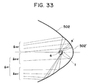
- Fig. 32 there is provided, in the vicinity of the optical axis of the reflector 502, with a reflector 502' of which focal point is positioned closer to the bottom of said reflector 502, than the focal point thereof, and Fig. 33 shows the converging state, in the vicinity of the light source 1, of the inversely traced rays from an off-axis point on the screen.
- a partial light beam l22 converges on the high luminance area ⁇ of the light source 1 by means of the reflector 502', so that an illuminating light beam of a high luminance is obtained corresponding to the partial light beam l22.
- a beam l211 reflected by the reflector 502 still converges on the other high luminance area ⁇ ' of the light source 1, as in Fig. 29.
- a beam l212 reflected by the reflector 502' is shifted from the high luminance area ⁇ ' toward the bottom of the reflector and does not return to the light emitting areas of the light source 1.
- the condenser lens 504 of the present embodiment may contain an aspherical face or may be replaced by a lens group. Also there may be employed a plastic lens composed for example of acrylic resin.
- Figs. 30 and 33 constitute a critical illuminating system, in which, for an axial point, a high luminance area ⁇ of the light source 1 is conjugate with the center of the illuminated object, and, for an off-axis point, both high luminance areas ⁇ , ⁇ ' of the light source 1 are conjugate with the peripheral area of the object.
- critical illumination is not attained in strict sense, since the off-axis point is illuminated not only by the high luminance areas ⁇ , ⁇ ' of the light source 1 but also by the light emitting areas in the vicinity because of remaining aberrations if sagittal rays etc. are considered.
- Such conjugate relationship are not the essential condition of the present invention. For example, if the focal point of the reflector 2 is displaced from the liquid crystal panel 6, Kehler illumination is attained both in the axial and off-axis points.
- the reflector is composed of a rotational elliptical face, but the concept of the present invention is applicable to any illuminating system such as a parabolic reflector, a spherical reflector or a reflector of a similar aspherical shape, that provides two converging areas in the vicinity of the light source, for the inversely traced light beam from an off-axis point. In such case it is necessary to add a condenser lens or lenses in suitable manner.
- the high-luminance light emitting area is not necessarily positioned at the focal point of the reflector.
- the present invention provides an optical apparatus capable of displaying an image of a high resolving power and a high luminance over the entire image frame.
- This invention relates to an optical system such as a projector, including a light source and an illuminating system.
- the projector of this invention is provided with: a light source having first and second high-luminance light-emitting areas; an illuminating optical system for directing the light from the light source toward an object to be illuminated, wherein the first and second high-luminance light-emitting areas are positioned on the optical axis of the illuminating optical system; and a projection optical system for projecting the light emerging from the illuminated object; wherein the illuminating optical system is constructed in such a manner that the central area of the illuminated object is illuminated by the light beam from the first high-luminance light-emitting area and the peripheral area of the illuminated object is illuminated by the light beam from the first and second high-luminance light-emitting areas.
Landscapes
- Engineering & Computer Science (AREA)
- Multimedia (AREA)
- Signal Processing (AREA)
- General Engineering & Computer Science (AREA)
- Chemical & Material Sciences (AREA)
- Crystallography & Structural Chemistry (AREA)
- Liquid Crystal (AREA)
- Projection Apparatus (AREA)
- Non-Portable Lighting Devices Or Systems Thereof (AREA)
Applications Claiming Priority (6)
| Application Number | Priority Date | Filing Date | Title |
|---|---|---|---|
| JP272699/91 | 1991-10-21 | ||
| JP3272699A JPH05113605A (ja) | 1991-10-21 | 1991-10-21 | 投写型表示装置 |
| JP314471/91 | 1991-11-28 | ||
| JP3314471A JPH05150363A (ja) | 1991-11-28 | 1991-11-28 | 投写型表示装置 |
| JP327615/91 | 1991-12-11 | ||
| JP3327615A JPH05165094A (ja) | 1991-12-11 | 1991-12-11 | 投写型表示装置 |
Publications (3)
| Publication Number | Publication Date |
|---|---|
| EP0545052A2 true EP0545052A2 (fr) | 1993-06-09 |
| EP0545052A3 EP0545052A3 (fr) | 1993-06-16 |
| EP0545052B1 EP0545052B1 (fr) | 1996-01-03 |
Family
ID=27336027
Family Applications (1)
| Application Number | Title | Priority Date | Filing Date |
|---|---|---|---|
| EP92117925A Expired - Lifetime EP0545052B1 (fr) | 1991-10-21 | 1992-10-20 | Dispositif d'illumination et projecteur l'utilisant |
Country Status (3)
| Country | Link |
|---|---|
| US (1) | US5692819A (fr) |
| EP (1) | EP0545052B1 (fr) |
| DE (1) | DE69207362T2 (fr) |
Cited By (3)
| Publication number | Priority date | Publication date | Assignee | Title |
|---|---|---|---|---|
| EP0603583B1 (fr) * | 1992-11-25 | 1998-06-10 | Canon Kabushiki Kaisha | Appareil de projection des images |
| US6024452A (en) * | 1997-04-22 | 2000-02-15 | 3M Innovative Properties Company | Prismatic light beam homogenizer for projection displays |
| CN105318228A (zh) * | 2014-07-28 | 2016-02-10 | 蒂雅克股份有限公司 | 指示器 |
Families Citing this family (44)
| Publication number | Priority date | Publication date | Assignee | Title |
|---|---|---|---|---|
| US5659409A (en) * | 1992-10-09 | 1997-08-19 | Ag Technology Co., Ltd. | Light source apparatus using a cone-like material and an applied apparatus thereof |
| US5910854A (en) | 1993-02-26 | 1999-06-08 | Donnelly Corporation | Electrochromic polymeric solid films, manufacturing electrochromic devices using such solid films, and processes for making such solid films and devices |
| US5668663A (en) | 1994-05-05 | 1997-09-16 | Donnelly Corporation | Electrochromic mirrors and devices |
| US6891563B2 (en) | 1996-05-22 | 2005-05-10 | Donnelly Corporation | Vehicular vision system |
| JPH10148885A (ja) * | 1996-11-19 | 1998-06-02 | Sony Corp | プロジェクタ装置 |
| US6326613B1 (en) | 1998-01-07 | 2001-12-04 | Donnelly Corporation | Vehicle interior mirror assembly adapted for containing a rain sensor |
| US6172613B1 (en) | 1998-02-18 | 2001-01-09 | Donnelly Corporation | Rearview mirror assembly incorporating vehicle information display |
| US8294975B2 (en) | 1997-08-25 | 2012-10-23 | Donnelly Corporation | Automotive rearview mirror assembly |
| US6124886A (en) | 1997-08-25 | 2000-09-26 | Donnelly Corporation | Modular rearview mirror assembly |
| US6445287B1 (en) | 2000-02-28 | 2002-09-03 | Donnelly Corporation | Tire inflation assistance monitoring system |
| US6690268B2 (en) | 2000-03-02 | 2004-02-10 | Donnelly Corporation | Video mirror systems incorporating an accessory module |
| US8288711B2 (en) | 1998-01-07 | 2012-10-16 | Donnelly Corporation | Interior rearview mirror system with forwardly-viewing camera and a control |
| US6477464B2 (en) | 2000-03-09 | 2002-11-05 | Donnelly Corporation | Complete mirror-based global-positioning system (GPS) navigation solution |
| US6693517B2 (en) | 2000-04-21 | 2004-02-17 | Donnelly Corporation | Vehicle mirror assembly communicating wirelessly with vehicle accessories and occupants |
| US6329925B1 (en) | 1999-11-24 | 2001-12-11 | Donnelly Corporation | Rearview mirror assembly with added feature modular display |
| US7195381B2 (en) | 2001-01-23 | 2007-03-27 | Donnelly Corporation | Vehicle interior LED lighting system |
| US7167796B2 (en) | 2000-03-09 | 2007-01-23 | Donnelly Corporation | Vehicle navigation system for use with a telematics system |
| US7370983B2 (en) | 2000-03-02 | 2008-05-13 | Donnelly Corporation | Interior mirror assembly with display |
| US6688756B1 (en) * | 2000-03-31 | 2004-02-10 | Seiko Epson Corporation | Light source device, and illuminating optical system and projector including the same |
| JP3920005B2 (ja) * | 2000-05-17 | 2007-05-30 | 株式会社小糸製作所 | 車両用標識灯 |
| US7581859B2 (en) | 2005-09-14 | 2009-09-01 | Donnelly Corp. | Display device for exterior rearview mirror |
| US7255451B2 (en) | 2002-09-20 | 2007-08-14 | Donnelly Corporation | Electro-optic mirror cell |
| JP2003043580A (ja) * | 2001-07-30 | 2003-02-13 | Mitsubishi Electric Corp | ランプ、偏光変換光学系および画像表示装置 |
| US6918674B2 (en) | 2002-05-03 | 2005-07-19 | Donnelly Corporation | Vehicle rearview mirror system |
| US7329013B2 (en) | 2002-06-06 | 2008-02-12 | Donnelly Corporation | Interior rearview mirror system with compass |
| EP1514246A4 (fr) | 2002-06-06 | 2008-04-16 | Donnelly Corp | Systeme de miroir de courtoisie interieur a boussole |
| US7274501B2 (en) | 2002-09-20 | 2007-09-25 | Donnelly Corporation | Mirror reflective element assembly |
| US7310177B2 (en) | 2002-09-20 | 2007-12-18 | Donnelly Corporation | Electro-optic reflective element assembly |
| US7289037B2 (en) | 2003-05-19 | 2007-10-30 | Donnelly Corporation | Mirror assembly for vehicle |
| US7446924B2 (en) | 2003-10-02 | 2008-11-04 | Donnelly Corporation | Mirror reflective element assembly including electronic component |
| US7308341B2 (en) | 2003-10-14 | 2007-12-11 | Donnelly Corporation | Vehicle communication system |
| TWI293707B (en) * | 2004-06-08 | 2008-02-21 | Prodisc Technology Inc | Liquid crystal display and backlight module |
| TWI247962B (en) * | 2004-10-19 | 2006-01-21 | Coretronic Corp | Projector |
| US7204599B2 (en) * | 2004-12-16 | 2007-04-17 | Hewlett-Packard Development Company, L.P. | Offset projection system |
| EP1883855B1 (fr) | 2005-05-16 | 2011-07-20 | Donnelly Corporation | Ensemble de retroviseur de vehicule comportant des informations sur l'element reflecteur |
| CN101535087B (zh) * | 2005-11-01 | 2013-05-15 | 唐纳利公司 | 具有显示装置的内部后视镜 |
| US8154418B2 (en) | 2008-03-31 | 2012-04-10 | Magna Mirrors Of America, Inc. | Interior rearview mirror system |
| US9487144B2 (en) | 2008-10-16 | 2016-11-08 | Magna Mirrors Of America, Inc. | Interior mirror assembly with display |
| TWI477883B (zh) * | 2013-01-22 | 2015-03-21 | Hon Hai Prec Ind Co Ltd | 背投電視的光機裝置 |
| JP5975012B2 (ja) * | 2013-11-19 | 2016-08-23 | 株式会社リコー | 画像投射装置 |
| WO2015132731A1 (fr) * | 2014-03-04 | 2015-09-11 | Koninklijke Philips N.V. | Appareil d'éclairage à double mode |
| US9507151B2 (en) * | 2014-10-10 | 2016-11-29 | The Boeing Company | Optical design of a wide field of view pupil forming HUD |
| US10466451B2 (en) * | 2017-12-04 | 2019-11-05 | Newmax Technology Co., Ltd. | Two-piece infrared single wavelength projection lens system |
| DE102022211866A1 (de) * | 2022-11-09 | 2024-05-16 | Carl Zeiss Smt Gmbh | Spiegelelement, Lithographiesystem und Verfahren zur Bereitstellung eines Spiegelelements |
Citations (4)
| Publication number | Priority date | Publication date | Assignee | Title |
|---|---|---|---|---|
| US4171874A (en) * | 1975-02-03 | 1979-10-23 | General Electric Company | Evenly illuminated display devices |
| DE3319562A1 (de) * | 1982-08-02 | 1984-02-02 | Jenoptik Jena Gmbh, Ddr 6900 Jena | Reflektorsystem fuer beleuchtungsoptiken |
| US4722593A (en) * | 1985-07-29 | 1988-02-02 | Casio Computer Co., Ltd. | Liquid-crystal projector with light beam reduction lens array for improved brightness of image outer portions |
| EP0440379A2 (fr) * | 1990-02-01 | 1991-08-07 | Sumitomo Metal Mining Company Limited | Dispositif d'éclairage |
Family Cites Families (9)
| Publication number | Priority date | Publication date | Assignee | Title |
|---|---|---|---|---|
| US3267802A (en) * | 1965-01-04 | 1966-08-23 | Gen Electric | Lenticulated collimating condensing system for oblique object planes |
| US3702395A (en) * | 1970-10-09 | 1972-11-07 | Us Navy | Condenser system for high intensity light source |
| EP0192023A3 (fr) * | 1985-02-21 | 1986-10-08 | Casio Computer Company Limited | Projecteur à cristal liquide |
| US4770525A (en) * | 1986-03-24 | 1988-09-13 | Casio Computer Co., Ltd. | Liquid crystal projector |
| JPS62266513A (ja) * | 1986-05-14 | 1987-11-19 | Canon Inc | 投影露光光学系 |
| JPH0244601A (ja) * | 1988-08-01 | 1990-02-14 | Stanley Electric Co Ltd | プロジェクタ型前照灯 |
| JPH02103084A (ja) * | 1988-10-12 | 1990-04-16 | Hitachi Ltd | 液晶プロジェクタ |
| JP2961807B2 (ja) * | 1990-04-20 | 1999-10-12 | 三菱電機株式会社 | 投写形表示装置 |
| US5192962A (en) * | 1990-05-29 | 1993-03-09 | Pioneer Electronic Corporation | Converging reflector and liquid crystal display device |
-
1992
- 1992-10-20 DE DE69207362T patent/DE69207362T2/de not_active Expired - Fee Related
- 1992-10-20 EP EP92117925A patent/EP0545052B1/fr not_active Expired - Lifetime
-
1995
- 1995-03-02 US US08/403,549 patent/US5692819A/en not_active Expired - Fee Related
Patent Citations (4)
| Publication number | Priority date | Publication date | Assignee | Title |
|---|---|---|---|---|
| US4171874A (en) * | 1975-02-03 | 1979-10-23 | General Electric Company | Evenly illuminated display devices |
| DE3319562A1 (de) * | 1982-08-02 | 1984-02-02 | Jenoptik Jena Gmbh, Ddr 6900 Jena | Reflektorsystem fuer beleuchtungsoptiken |
| US4722593A (en) * | 1985-07-29 | 1988-02-02 | Casio Computer Co., Ltd. | Liquid-crystal projector with light beam reduction lens array for improved brightness of image outer portions |
| EP0440379A2 (fr) * | 1990-02-01 | 1991-08-07 | Sumitomo Metal Mining Company Limited | Dispositif d'éclairage |
Non-Patent Citations (2)
| Title |
|---|
| PATENT ABSTRACTS OF JAPAN vol. 014, no. 206 (M-967)14 February 1990 & JP-A-02 044 601 ( STANLEY ELECTRIC ) 14 February 1990 * |
| PATENT ABSTRACTS OF JAPAN vol. 014, no. 317 (P-1073)9 July 1990 & JP-A-02 103 084 ( HITACHI ) 16 April 1990 * |
Cited By (4)
| Publication number | Priority date | Publication date | Assignee | Title |
|---|---|---|---|---|
| EP0603583B1 (fr) * | 1992-11-25 | 1998-06-10 | Canon Kabushiki Kaisha | Appareil de projection des images |
| US6024452A (en) * | 1997-04-22 | 2000-02-15 | 3M Innovative Properties Company | Prismatic light beam homogenizer for projection displays |
| CN105318228A (zh) * | 2014-07-28 | 2016-02-10 | 蒂雅克股份有限公司 | 指示器 |
| US10295381B2 (en) | 2014-07-28 | 2019-05-21 | Teac Corporation | Indicator |
Also Published As
| Publication number | Publication date |
|---|---|
| EP0545052B1 (fr) | 1996-01-03 |
| EP0545052A3 (fr) | 1993-06-16 |
| DE69207362D1 (de) | 1996-02-15 |
| US5692819A (en) | 1997-12-02 |
| DE69207362T2 (de) | 1996-06-13 |
Similar Documents
| Publication | Publication Date | Title |
|---|---|---|
| EP0545052B1 (fr) | Dispositif d'illumination et projecteur l'utilisant | |
| US6464375B2 (en) | Lens element and illumination optical apparatus and projection display apparatus | |
| JP3347676B2 (ja) | 照明装置およびそれを用いた投射型表示装置 | |
| US6669345B2 (en) | Illumination system and projector | |
| JP2000137204A (ja) | 照明装置およびそれを用いた投射型表示装置 | |
| US6857752B2 (en) | Projection illumination system with tunnel integrator and field lens | |
| US6831707B2 (en) | Liquid crystal display element and projection type liquid crystal display device | |
| EP0405953B1 (fr) | Appareil-source de lumière pour séparer la lumière blanche en composantes de différentes couleurs | |
| RU2199144C2 (ru) | Устройство проекционного дисплея | |
| JPH10115871A (ja) | 画像投射装置 | |
| JP3870191B2 (ja) | 多色画像をプロジェクションスクリーンに投影するための装置 | |
| JP3278084B2 (ja) | 表示装置及びそれを用いた投射装置 | |
| JPH08201756A (ja) | 液晶プロジェクター | |
| KR100342651B1 (ko) | 다중 스크린을 갖는 프로젝션 시스템 | |
| JPH1010467A (ja) | 投影表示装置 | |
| JP3486608B2 (ja) | 投写型表示装置 | |
| KR100389024B1 (ko) | 단판식 액정패널의 광학계 | |
| JP2004519745A (ja) | プロジェクションスクリーンに画像を投影するための装置 | |
| KR100359728B1 (ko) | 액정 프로젝터의 광학 장치 | |
| JPH11271881A (ja) | 像を投写・表示するシステム | |
| JP2000098488A (ja) | 照明光学装置 | |
| JP3365412B2 (ja) | 投写型表示装置 | |
| JP3327908B2 (ja) | 表示装置及びそれを用いた投射装置 | |
| JPH07294922A (ja) | 表示装置及びそれを用いた投射装置 | |
| JP3506142B1 (ja) | 投写型表示装置 |
Legal Events
| Date | Code | Title | Description |
|---|---|---|---|
| PUAI | Public reference made under article 153(3) epc to a published international application that has entered the european phase |
Free format text: ORIGINAL CODE: 0009012 |
|
| PUAL | Search report despatched |
Free format text: ORIGINAL CODE: 0009013 |
|
| AK | Designated contracting states |
Kind code of ref document: A2 Designated state(s): DE FR GB |
|
| AK | Designated contracting states |
Kind code of ref document: A3 Designated state(s): DE FR GB |
|
| 17P | Request for examination filed |
Effective date: 19931102 |
|
| 17Q | First examination report despatched |
Effective date: 19940627 |
|
| GRAA | (expected) grant |
Free format text: ORIGINAL CODE: 0009210 |
|
| AK | Designated contracting states |
Kind code of ref document: B1 Designated state(s): DE FR GB |
|
| REF | Corresponds to: |
Ref document number: 69207362 Country of ref document: DE Date of ref document: 19960215 |
|
| ET | Fr: translation filed | ||
| PLBE | No opposition filed within time limit |
Free format text: ORIGINAL CODE: 0009261 |
|
| STAA | Information on the status of an ep patent application or granted ep patent |
Free format text: STATUS: NO OPPOSITION FILED WITHIN TIME LIMIT |
|
| 26N | No opposition filed | ||
| REG | Reference to a national code |
Ref country code: GB Ref legal event code: IF02 |
|
| PGFP | Annual fee paid to national office [announced via postgrant information from national office to epo] |
Ref country code: FR Payment date: 20041008 Year of fee payment: 13 |
|
| PGFP | Annual fee paid to national office [announced via postgrant information from national office to epo] |
Ref country code: DE Payment date: 20041014 Year of fee payment: 13 |
|
| PGFP | Annual fee paid to national office [announced via postgrant information from national office to epo] |
Ref country code: GB Payment date: 20041020 Year of fee payment: 13 |
|
| PG25 | Lapsed in a contracting state [announced via postgrant information from national office to epo] |
Ref country code: GB Free format text: LAPSE BECAUSE OF NON-PAYMENT OF DUE FEES Effective date: 20051020 |
|
| PG25 | Lapsed in a contracting state [announced via postgrant information from national office to epo] |
Ref country code: DE Free format text: LAPSE BECAUSE OF NON-PAYMENT OF DUE FEES Effective date: 20060503 |
|
| GBPC | Gb: european patent ceased through non-payment of renewal fee |
Effective date: 20051020 |
|
| PG25 | Lapsed in a contracting state [announced via postgrant information from national office to epo] |
Ref country code: FR Free format text: LAPSE BECAUSE OF NON-PAYMENT OF DUE FEES Effective date: 20060630 |
|
| REG | Reference to a national code |
Ref country code: FR Ref legal event code: ST Effective date: 20060630 |