EP0544129B2 - Spanneinrichtung für eine Stichsägemaschine - Google Patents
Spanneinrichtung für eine Stichsägemaschine Download PDFInfo
- Publication number
- EP0544129B2 EP0544129B2 EP19920118923 EP92118923A EP0544129B2 EP 0544129 B2 EP0544129 B2 EP 0544129B2 EP 19920118923 EP19920118923 EP 19920118923 EP 92118923 A EP92118923 A EP 92118923A EP 0544129 B2 EP0544129 B2 EP 0544129B2
- Authority
- EP
- European Patent Office
- Prior art keywords
- sleeve
- clamping
- clamping device
- centring
- jaws
- Prior art date
- Legal status (The legal status is an assumption and is not a legal conclusion. Google has not performed a legal analysis and makes no representation as to the accuracy of the status listed.)
- Expired - Lifetime
Links
- UPMXNNIRAGDFEH-UHFFFAOYSA-N 3,5-dibromo-4-hydroxybenzonitrile Chemical compound OC1=C(Br)C=C(C#N)C=C1Br UPMXNNIRAGDFEH-UHFFFAOYSA-N 0.000 title claims 4
- 230000037431 insertion Effects 0.000 claims 2
- 238000003780 insertion Methods 0.000 claims 2
- 230000010355 oscillation Effects 0.000 claims 1
- 230000006835 compression Effects 0.000 description 8
- 238000007906 compression Methods 0.000 description 8
- 210000001331 nose Anatomy 0.000 description 4
- 208000027418 Wounds and injury Diseases 0.000 description 3
- 230000006378 damage Effects 0.000 description 3
- 210000003128 head Anatomy 0.000 description 3
- 208000014674 injury Diseases 0.000 description 3
- 230000002349 favourable effect Effects 0.000 description 2
- 238000000034 method Methods 0.000 description 2
- 230000002411 adverse Effects 0.000 description 1
- 238000013459 approach Methods 0.000 description 1
- 230000001771 impaired effect Effects 0.000 description 1
- 230000036316 preload Effects 0.000 description 1
- 238000007789 sealing Methods 0.000 description 1
Images


Classifications
-
- B—PERFORMING OPERATIONS; TRANSPORTING
- B23—MACHINE TOOLS; METAL-WORKING NOT OTHERWISE PROVIDED FOR
- B23D—PLANING; SLOTTING; SHEARING; BROACHING; SAWING; FILING; SCRAPING; LIKE OPERATIONS FOR WORKING METAL BY REMOVING MATERIAL, NOT OTHERWISE PROVIDED FOR
- B23D51/00—Sawing machines or sawing devices working with straight blades, characterised only by constructional features of particular parts; Carrying or attaching means for tools, covered by this subclass, which are connected to a carrier at both ends
- B23D51/08—Sawing machines or sawing devices working with straight blades, characterised only by constructional features of particular parts; Carrying or attaching means for tools, covered by this subclass, which are connected to a carrier at both ends of devices for mounting straight saw blades or other tools
- B23D51/10—Sawing machines or sawing devices working with straight blades, characterised only by constructional features of particular parts; Carrying or attaching means for tools, covered by this subclass, which are connected to a carrier at both ends of devices for mounting straight saw blades or other tools for hand-held or hand-operated devices
-
- Y—GENERAL TAGGING OF NEW TECHNOLOGICAL DEVELOPMENTS; GENERAL TAGGING OF CROSS-SECTIONAL TECHNOLOGIES SPANNING OVER SEVERAL SECTIONS OF THE IPC; TECHNICAL SUBJECTS COVERED BY FORMER USPC CROSS-REFERENCE ART COLLECTIONS [XRACs] AND DIGESTS
- Y10—TECHNICAL SUBJECTS COVERED BY FORMER USPC
- Y10T—TECHNICAL SUBJECTS COVERED BY FORMER US CLASSIFICATION
- Y10T279/00—Chucks or sockets
- Y10T279/17—Socket type
- Y10T279/17863—Shouldered-tang holding
- Y10T279/17871—Cap
-
- Y—GENERAL TAGGING OF NEW TECHNOLOGICAL DEVELOPMENTS; GENERAL TAGGING OF CROSS-SECTIONAL TECHNOLOGIES SPANNING OVER SEVERAL SECTIONS OF THE IPC; TECHNICAL SUBJECTS COVERED BY FORMER USPC CROSS-REFERENCE ART COLLECTIONS [XRACs] AND DIGESTS
- Y10—TECHNICAL SUBJECTS COVERED BY FORMER USPC
- Y10T—TECHNICAL SUBJECTS COVERED BY FORMER US CLASSIFICATION
- Y10T83/00—Cutting
- Y10T83/929—Tool or tool with support
- Y10T83/9457—Joint or connection
Definitions
- the invention relates to a clamping device for the saw blade a hand-held jigsaw according to the generic term of claim 1.
- Such a tensioning device is in EP 0 404 764B1 described.
- the end area of the saw blade is in the centering sleeve guided with side play, which is a precise Clamping of the saw blade impaired.
- the change of the saw blade to be operated makes the Movement of the saw blade is not included.
- centering sleeve In the centering sleeve according to DE 41 02 011 A1 is a one-piece, spring-loaded centering bolt mounted, the the end area of the clamping end of the saw blade supports. Between the centering pin and the Centering sleeve is inevitably a game. this leads to to undesired lateral movements of the saw blade. Such Lateral movements reduce the precision of the saw cut.
- the object of the invention is a tensioning device to suggest the handling mentioned the jigsaw improved, especially that Actuator the movement of the saw blade despite being more precise Clamping the saw blade does not participate.
- the above object is for a tensioning device of the type mentioned above by the characteristic Features of claim 1 solved.
- the invention has the advantage that the saw blades too with different thicknesses guided in the center and the end area of the respective saw blade is intermediate the centering jaw is clamped. This improves the cutting precision of the jigsaw machine considerably.
- the actuator So neither the switching sleeve nor its handle, the movement of the saw blade.
- the switch sleeve is in sawing mode free from the adapter sleeve and stands still. This reduces the risk of injury and improves it Manageability of the jigsaw and also the operability of the actuator when inserting or changing the saw blade.
- the switching sleeve has an inner wall area that the clamping sleeve is closer than the wall and the rest of it Inner wall area when actuating the switching sleeve pendulum adapter sleeve to an end point of the Pendulum stop presses. This ensures that the Centering sleeve and the clamping sleeve for inserting a Saw blade in a defined position of the pendulum stroke brought in which the saw blade is easily inserted can be.
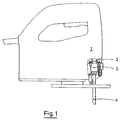
- a hand-held jigsaw has a housing (1) on. In this is a motor-driven plunger (2) stored.
- a clamping device (3) is located on the tappet (2) arranged with the ram (2) in the saw stroke (S), if necessary, also oscillating, driven becomes.
- a saw blade (4) is on the tensioning device (3) its clamping end (5) can be determined. At the end of the clamp (5) two lugs (6) are formed. In Figures 2 and 3 the saw blade (4) is shown in double-dashed lines.
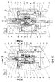
- the centering sleeve (7) has a External thread (8) on which by means of an internal thread (9) an adapter sleeve (10) is mounted.
- the threads (8.9) form an inclined surface, by means of which the clamping sleeve (10) in the direction of the longitudinal axis (L) axially opposite the Centering sleeve (7) is movable.
- Torsion spring (11) Between the Centering sleeve (7) and the clamping sleeve (10) is one Torsion spring (11) arranged.
- the centering sleeve (7) is at its lower end wedge-shaped inclined surfaces (12) for guiding the lugs (6) provided (see Fig. 3).
- the clamping sleeve (10) has one lower edge (13), which when clamping the Saw blade (4) the lugs (6) against the inclined surfaces (12) presses.
- centering bolt loaded by means of a compression spring (15) stored which is formed by two centering jaws (16, 17) is on which one of the compression spring (15) loaded Insert (18) abuts.
- the insert (18) presses on a slope (19) of each of the centering jaws (16, 17), the centering jaws (16, 17) being pressed outwards become.
- the centering jaws (16, 17) have guide surfaces (20) on the flattenings (21) of the centering sleeve (7) issue.
- the centering jaws (16, 17) are thereby in the Centering sleeve (7) cannot be rotated around the longitudinal axis (L) stored.
- the housing (1) In the housing (1) is an actuator for the Clamping sleeve (10) a switching sleeve (27) rotatably mounted.
- the switching sleeve (27) has a recess (30), the a side wall forms a stop edge (31).
- This Stop edge (31) extends parallel to Longitudinal axis (L) over a distance longer than that Saw stroke (S) is.
- the stop edge (31) stands Operating cams (32) opposite the clamping sleeve (10).
- a tension spring (33) acts on the switching sleeve (27).
- the Wall (34) of the switching sleeve (27) is oval in shape, so that the clamping sleeve (10) is located within the switching sleeve (27) can move freely, even if in addition to the saw stroke performs a pendulum motion. This is double-dashed in Figure 4 indicated.
- An inner wall area (35) the wall (34) is closer to the clamping sleeve (10) than that Wall (34) in the area of the pendulum stroke.
- the switching sleeve (27) is in its unactuated position (cf. FIG. 4). In this position, the clamping sleeve (10) or its actuating cam (32) does not touch the switching sleeve (27) either during the saw stroke in the direction of the longitudinal axis (L) or during an additional pendulum stroke.
- the switching sleeve (27) is held in this position by the tension spring (33), the handle member (28) striking an edge of the opening (29).
- the saw blade (4) If the saw blade (4) is to be replaced, then it will Handle member (28) in the direction of arrow (A) (see FIG. 4) panned.
- the switching sleeve (27) turns against it the force of the tension spring (33) about the axis of rotation (D).
- the Actuation cam (32) stands on the actuation cam (32) and thereby rotates the clamping sleeve (10) against the force the torsion spring (11) in its release position, as shown in Figure 5 is shown.
- the switch sleeve (27) turns under the action of the torsion spring (11) with her Edge (13) under the lugs (6) and clamps them axially against the inclined surfaces (12). So the saw machine is back ready for use.
- the thickness of the saw blade (4) determines the Angular position of the actuating cam (32) of the Stop edge (31) within the recess (30).
- the respective saw blade (4) is independent of it Thickness at his noses (6) in the middle between the Fixed inclined surfaces (12). At the upper end area (14) of the Clamping (5) is the saw blade (4) additionally through the spring-loaded centering jaws (16, 17) or their Sloping surfaces (22) held. It is also about that Longitudinal axis (L) kept non-rotatable without play.
- the torsion spring (11) must therefore only a comparatively low torque apply to the desired clamping of the saw blade (4) to reach.
- the switching sleeve in any stroke position of the saw blade can be operated without a There is a risk of injury to the user and without further returns to a safe starting position.
- the saw blade (4) can also be released, as long as the plunger (2) is still moving.
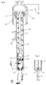
- the centering jaws (16, 17) are on a pin (36) stored and non-rotatable in the centering sleeve (7) guided.
- the pin (36) extends through both ends Openings (37) of the centering sleeve (7) in an annular channel (38) the adapter sleeve (10).
- Each centering jaw (16, 17) has an inclined surface (22) on which the End region (14) of the clamping end (5) of the saw blade (4) runs in a wedge shape.
- the centering jaws (16, 17) can thus also of different thicknesses (see Fig. 7) Hold the saw blades between you. Wedge-shaped Sloping surfaces (12) to support the lugs (6) of the Saw blades (4) are at the bottom of the centering sleeve (7) educated.
- the mode of operation of the exemplary embodiment according to FIGS. 6, 7 is essentially as follows:
- the saw blade (4) is centered regardless of its thickness, has a positive fit without play and is clamped non-rotatably about the longitudinal axis (L).
- the clamping sleeve (10) is rotated along the threads (8, 9) relative to the centering sleeve (7).
- the upper edge of the ring channel (38) presses the pin (36) downwards and in the longitudinal direction (L) presses the centering jaws (16, 17) with their inclined surfaces (22) onto the clamping end (5), which in the process is in the wedge shape Recesses (23) of the centering jaws (16, 17).
- the lugs (6) are thereby pressed between the wedge-shaped inclined surfaces (12) of the centering sleeve (7).
- the two centering jaws (16, 17) rest against the center of the centering sleeve (7) without play.
- the clamping sleeve (10) is rotated relative to the centering sleeve (7), as described in the exemplary embodiment according to FIGS. 1 to 4. It then travels along the threads (8, 9) against the action of the torsion spring (11) in the longitudinal direction (L) and takes with its lower edge of its ring channel (38) the pin (36), which thereby the centering jaws (16, 17) from the end region (14) of the clamping end (5).
- the saw blade (4) can now be removed from the centering sleeve (7) from the inclined surfaces (12) and after turning by about 90 o .
- a different saw blade can then be used, which, regardless of whether it is thicker or thinner, is positively, centered, clamped without play in the manner described under the action of the torsion spring (11).
- the handle member (28) on the housing (1) comparatively close for the saw blade (4) (see Fig. 1).
- the Switch sleeve (27) and its handle member (28) further from that Saw blade (4) are arranged on the housing (1).
- the Centering sleeve (7) extends far behind in the housing (1) above.
- an attachment (39) is attached to the centering sleeve (7).
- the clamping sleeve (10) is at the top of the Centering sleeve (7) mounted by means of the thread (8,9).
- a Extension (40) of the clamping sleeve (10) extends in the Centering sleeve (7) down and has one Recording head (41) for the wedge-shaped end region (14) of the Clamping end (5) of the saw blade (4).
- At the Recording head (41) is a funnel-shaped, conical, the Recess (42) adapted to the wedge shape of the end region (14) educated.
- the receiving head (41) is with a sealing ring (43) in the Centering sleeve (7) supported.
- the centering sleeve (7) has the wedge-shaped inclined surfaces (12) to support the Noses (6).
- the torsion spring (11) engages on the one hand Receiving head (41) and on the other hand on the centering sleeve (7) on.
- the recess (42) of the receiving head (41) is in operation under the action of the torsion spring (11) and the thread (8,9) pressed on the clamping end (5). This is included form-fitting. This also makes the noses (6) pressed between the inclined surfaces (12).
- a cross pin (44) is arranged on the centering sleeve (7), on which two arms (45, 46) are pivotally mounted.
- everyone Arm (45, 46) has on its facing away from the cross pin (44) End of a clamping jaw (47) for each of the lugs (6) of the saw blade (4).
- the Bulges (49) is an inner cone (50) of the clamping sleeve (10) assigned.
- bevels (51) are provided, on which a compression spring (52) presses on a collar (53) of the centering bolt supports.
- the mode of operation of the exemplary embodiment according to FIGS. 10, 11 is essentially as follows: In the clamping position (see Fig. 10, 11), the inner cone (50) presses the receptacles (48) of the clamping jaws (47) over the lugs (6), which are thereby kept free of play. As described, the compression spring (15) presses the inclined surfaces (22) of the centering jaws (16, 17) against the end region (14) of the clamping end (5). The saw blade (4) is clamped in the desired manner without play and non-rotatably.
- the spring (11) not be a torsion spring. It can be a compression spring. The clamping sleeve or switching sleeve are then manually in the Bring clamping position.
Landscapes
- Engineering & Computer Science (AREA)
- Mechanical Engineering (AREA)
- Sawing (AREA)
Description
In den Figuren 2 und 3 ist die Spannhülse(10) in ihrer Klemmstellung gezeigt. In dieser Stellung ist sie mittels der Drehfeder(11) am Gewinde(8,9) so nach oben geschraubt, daß ihr Rand(13) die Nasen(6) des Sägeblatts(4) nach oben gegen die Schrägflächen(12) drückt. Damit ist das Sägeblatt(4) unabhängig von seiner Dicke sicher festgeklemmt. Der Endbereich(14) des Sägeblatts(4) ist von den Zentrierbacken(16,17) radial spielfrei gehalten, die ihrerseits radial spielfrei in der Zentrierhülse(7) geführt sind. Der Endbereich(14) des Sägeblatts(4) kann somit auch bei Querbelastung des Sägeblatts(4) beim Schnitt nicht ausweichen. Dies verbessert die Schnittpräzision. Während des Sägebetriebs steht die Schalthülse(27) in ihrer unbetätigten Stellung (vgl. Figur 4). In dieser Stellung berührt die Spannhülse(10) bzw. ihr Betätigungsnocken(32) die Schalthülse(27) weder beim in Richtung der Längsachse(L) erfolgenden Sägehub noch bei einem zusätzlichen Pendelhub. Die Schalthülse(27) ist in dieser Stellung von der Zugfeder(33) gehalten, wobei das Griffglied(28) an einem Rand der Durchbrechung(29) anschlägt.
Im Betrieb ist das Sägeblatt(4) unabhängig von seiner Dicke zentriert, spielfrei formschlüssig und um die Längsachse(L) unverdrehbar fest eingespannt. Im gespannten Zustand ist unter der Wirkung der Drehfeder(11) die Spannhülse(10) längs der Gewinde(8,9) gegenüber der Zentrierhülse(7) gedreht. Dabei drückt der obere Rand des Ringkanals(38) den Zapfen(36) nach unten und dieser drückt in Längsrichtung(L) die Zentrierbacken (16,17) mit ihren Schrägflächen(22) auf das Einspannende(5), das dabei in den keilförmigen Ausnehmungen(23) der Zentrierbacken(16,17) liegt. Die Nasen(6) sind dadurch zwischen die keilförmigen Schrägflächen(12) der Zentrierhülse(7) gedrückt. In Gegenwirkung zur auf das Einspannende(5) wirkenden Anspannkraft legen sich die beiden Zentrierbacken(16,17) spielfrei innen an der Zentrierhülse(7) an.
In der Einspannstellung (vgl. Fig.10, 11) drückt der Innenkonus(50) die Aufnahmen(48) der Spannbacken(47) über die Nasen(6), die dadurch spielfrei gehalten sind. Die Druckfeder(15) drückt, wie beschrieben, die Schrägflächen (22) der Zentrierbacken(16,17) an den Endbereich(14) des Einspannendes(5). Das Sägeblatt(4) ist dadurch in der gewünschten Weise spielfrei und unverdrehbar festgespannt.
Claims (14)
- Spanneinrichtung für das Sägeblatt(4) einer handgeführten Stichsägemaschine, das von einem im Gehäuse der Stichsägemaschine im Sägehub angetriebenen Stößel(2) parallel zu seiner Längsachse(L) bewegbar ist und das an seinem Einspannende(5) zwei Nasen(6) aufweist, mit einer Zentrierhülse(7), in die das Einspannende(5) einsteckbar ist, und mit einem Stellglied zum Lösen des Sägeblatts (4), wobei eine um die Längsachse(L) verdrehbar gelagerte Spannhülse(10) vorgesehen ist, die mittels einer Schrägfläche(8,9) und einer Feder(11) eine die Nasen des Einspannendes(5) in der Zentrierhülse(7) festklemmende Axialbewegung ausführt, und mittels des Stellgliedes die Spannhülse(10) aus der Klemmstellung gegen die Kraft der Feder (11) in die Freigabestellung drehbar ist, und das Stellglied von einer im Gehäuse(1) etwa um die Längsachse(L) schwenkbar, axial unverschieblich gelagerten Schalthülse (27) gebildet ist, und die Schalthülse(27) mit einem Griffglied(28) eine Durchbrechung(29) des Gehäuses(1) überragt und die Schalthülse(27) einen Anschlagrand(31) bildet, der in axialer Richtung mindestens so lang wie der Sägehub(S) ist, wobei der Anschlagrand(31) einem Betätigungsnocken(32) der Spannhülse(10) gegenübersteht und bei Betätigung des Griffgliedes(28) die Spannhülse (10) aus ihrer Klemmstellung in die Freigabestellung dreht,
dadurch gekennzeichnet,
daß in der Zentrierhülse(7) Zentrierbacken(16,17) geführt sind, die mittels Schrägflächen(22) beidseitig den Endbereich(14) des Einspannendes(5) des Sägeblatts(4) klemmen. - Spanneinrichtung nach Anspruch 1, dadurch gekennzeichnet, daß die Drehachse(D) der Schalthülse(27) parallel zur Längsachse(L) liegt.
- Spanneinrichtung nach Anspruch 1 oder 2, dadurch gekennzeichnet, daß an der Schalthülse-(7) eine Rückstellfeder(33) angreift.
- Spanneinrichtung nach Anspruch 3, dadurch gekennzeichnet, daß die Rückstellfeder(33) die Schalthülse(27) in eine Ruhestellung bringt, in der ihr Anschlagrand(31) von dem Betätigungsnocken(32) beabstandet ist.
- Spanneinrichtung nach einem der vorhergehenden Ansprüche, insbesondere bei einer Pendel-Stichsäge, dadurch gekennzeichnet, daß die Schalthülse(27) einen Innenwandungsbereich(35) aufweist, der der Spannhülse(10) nähersteht als die Wandung im übrigen, und daß der Innenwandungsbereich(35) beim Betätigen der Schalthülse (27) die pendelbare Spannhülse-(10) an einen Endpunkt des Pendelausschlags drückt.
- Spanneinrichtung nach Anspruch 5, dadurch gekennzeichnet, daß die Wandung der Schalthülse(27) im Querschnitt oval ist.
- Spanneinrichtung nach einem der vorhergehenden Ansprüche 2 bis 6, dadurch gekennzeichnet, daß die Drehachse(D) zwischen der Längsachse(L) und dem Innenwandungsbereich(35) liegt.
- Spanneinrichtung nach einem der vorhergehenden Ansprüche,
dadurch gekennzeichnet,
daß die zwei Zentrierbacken(16,17) von einer Feder(15) spielfrei an die Zentrierhülse(7) angedrückt sind. - Spanneinrichtung nach Anspruch 8, dadurch gekennzeichnet, daß die Zentrierbacken(16,17) in der Zentrierhülse(7) um die Längsachse(L) unverdrehbar geführt sind.
- Spanneinrichtung nach Anspruch 8, dadurch gekennzeichnet, daß die Zentrierbacken(16,17) aus einem Stück bestehen, wobei die Verbindung federnd ist und die Zentrierbacken(16,17) mit Vorspannung nach außen eingebaut sind.
- Spanneinrichtung nach einem der vorhergehenden Ansprüche, dadurch gekennzeichnet, daß die zwischen der Spannhülse(10) und der Zentrierhülse(7) wirkende Feder eine Drehfeder(11) ist.
- Spanneinrichtung nach einem der vorhergehenden Ansprüche, dadurch gekennzeichnet, daß die Spannhülse(10) bei ihrer Bewegung zwei Zentrierbacken(16,17) für den Endbereich(14) des Einspannendes(5) axial mitnimmt.
- Spanneinrichtung nach einem der vorhergehenden Ansprüche, dadurch gekennzeichnet, daß die Spannhülse(10) einen Aufnahmekopf(41) mit einer trichterförmigen Vertiefung(42) für die Aufnahme des keilförmigen Endbereichs(14) des Einspannendes(5) aufweist.
- Spanneinrichtung nach einem der vorhergehenden Ansprüche, dadurch gekennzeichnet, daß in der Zentrierhülse(7) Spannbacken(47) aufweisende Arme(45,46) schwenkbar gelagert sind und daß die Spannbacken(47) mittels der Spannhülse(10) an die Nasen(6) andrückbar sind.
Applications Claiming Priority (3)
| Application Number | Priority Date | Filing Date | Title |
|---|---|---|---|
| DE4138986 | 1991-11-27 | ||
| DE19914138986 DE4138986A1 (de) | 1991-11-27 | 1991-11-27 | Spanneinrichtung fuer eine stichsaegemaschine |
| US08/038,716 US5306025A (en) | 1991-11-27 | 1993-03-26 | Clamping device for a compass sawing machine |
Publications (3)
| Publication Number | Publication Date |
|---|---|
| EP0544129A1 EP0544129A1 (de) | 1993-06-02 |
| EP0544129B1 EP0544129B1 (de) | 1995-01-25 |
| EP0544129B2 true EP0544129B2 (de) | 2000-03-01 |
Family
ID=25909543
Family Applications (1)
| Application Number | Title | Priority Date | Filing Date |
|---|---|---|---|
| EP19920118923 Expired - Lifetime EP0544129B2 (de) | 1991-11-27 | 1992-11-05 | Spanneinrichtung für eine Stichsägemaschine |
Country Status (4)
| Country | Link |
|---|---|
| US (1) | US5306025A (de) |
| EP (1) | EP0544129B2 (de) |
| DE (2) | DE4138986A1 (de) |
| ES (1) | ES2069364T5 (de) |
Families Citing this family (61)
| Publication number | Priority date | Publication date | Assignee | Title |
|---|---|---|---|---|
| US5340129A (en) * | 1993-01-21 | 1994-08-23 | Minnesota Mining And Manufacturing Company | Saw blade retention system |
| USRE36269E (en) * | 1993-01-21 | 1999-08-17 | Minnesota Mining And Manufacturing Company | Saw blade retention system |
| DE4311161A1 (de) * | 1993-04-05 | 1994-10-06 | Kress Elektrik Gmbh & Co | Schnellspannvorrichtung für Stichsägeblätter |
| JP3212792B2 (ja) * | 1994-02-10 | 2001-09-25 | 株式会社マキタ | ジグソー |
| EP0930121B1 (de) * | 1994-12-02 | 2002-04-24 | Makita Corporation | Schneidwerkzeugaufspannvorrichtung |
| DE69621268T2 (de) * | 1995-02-15 | 2003-01-09 | Makita Corp., Anjo | Sägeblattaufspannvorrichtung für Schneidwerkzeuge |
| DE19509539A1 (de) * | 1995-03-16 | 1996-09-19 | Bosch Gmbh Robert | Stichsägemaschine |
| DE19509544A1 (de) * | 1995-03-16 | 1996-09-26 | Scintilla Ag | Stichsäge |
| CN1065161C (zh) * | 1995-03-16 | 2001-05-02 | 星蒂拉公开股份有限公司 | 圆锯提升杆的导向和锯条夹紧装置 |
| US7325315B2 (en) * | 1995-06-09 | 2008-02-05 | Black & Decker Inc. | Clamping arrangement for receiving a saw blade in multiple orientations |
| US5647133A (en) * | 1995-06-09 | 1997-07-15 | Black & Decker Inc. | Saw blade clamping arrangement for a power tool |
| US6023848A (en) * | 1995-06-09 | 2000-02-15 | Black & Decker Inc. | Saw blade clamping arrangement for a power tool |
| US6295736B1 (en) | 1995-06-09 | 2001-10-02 | Black & Decker Inc. | Blade ejection mechanism for a saw blade clamping arrangement of a power tool |
| US6009627A (en) * | 1995-06-09 | 2000-01-04 | Black & Decker Inc. | Saw blade clamping arrangement for a power tool |
| US6944959B2 (en) | 1995-06-09 | 2005-09-20 | Black & Decker Inc. | Clamping arrangement for receiving a saw blade in multiple orientations |
| DE19521246B4 (de) * | 1995-06-10 | 2006-02-09 | Scintilla Ag | Stichsäge |
| DE19609396A1 (de) * | 1996-03-01 | 1997-09-04 | Black & Decker Inc | Motorgetriebene Stichsäge |
| GB9604463D0 (en) * | 1996-03-01 | 1996-05-01 | Black & Decker Inc | A saw blade clamp |
| US6725548B1 (en) | 1996-03-01 | 2004-04-27 | Milwaukee Electric Tool Corporation | Keyless blade clamp mechanism |
| DE69712390T2 (de) * | 1996-03-01 | 2002-12-19 | Black & Decker Inc., Newark | Motorisierte Stichsäge |
| EP0883459B1 (de) * | 1996-03-01 | 2003-09-17 | Milwaukee Electric Tool Corporation | Schlüssellose sägeblatteinspannvorrichtung |
| DE69714651T2 (de) * | 1996-05-23 | 2003-03-13 | Black & Decker Inc., Newark | Sägeblattaufspannvorrichtung für ein motorisiertes Werkzeug |
| DE19804706B4 (de) * | 1997-02-25 | 2011-03-03 | Scintilla Ag | Handgeführte Stichsägemaschine |
| GB2322593B (en) | 1997-02-28 | 1999-05-05 | Bosch Gmbh Robert | Clamping mechanism for a power tool |
| DE19819528A1 (de) * | 1998-04-30 | 1999-11-04 | Scintilla Ag | Handwerkzeugmaschine |
| US6467177B2 (en) | 1998-07-02 | 2002-10-22 | Black & Decker Inc. | Reciprocating saw blade clamp |
| DE19831222A1 (de) * | 1998-07-02 | 2000-01-05 | Black & Decker Inc | Sägeblattklemme für eine Stichsäge o. ä. |
| US6357124B1 (en) | 1998-07-10 | 2002-03-19 | Porter-Cable Corporation | Clamp system for a jigsaw tilt base |
| US6178646B1 (en) | 1998-07-10 | 2001-01-30 | Porter-Cable Corporation | Blade clamping system for a jigsaw |
| EP0970771A3 (de) * | 1998-07-10 | 2000-05-03 | Porter-Cable Corporation | Stichsägeblattspannvorrichtung mit nockenbetätigtem Spannelement |
| US6209208B1 (en) | 1998-10-09 | 2001-04-03 | Milwaukee Electric Tool Corporarion | Keyless blade clamp mechanism |
| DE29819601U1 (de) * | 1998-11-03 | 2000-03-09 | Scintilla Ag, Solothurn | Handwerkzeugmaschine |
| GB9827940D0 (en) | 1998-12-18 | 1999-02-10 | Black & Decker Inc | A power saw |
| USD460672S1 (en) | 1999-10-20 | 2002-07-23 | Lidl Stiftung & Co Kg | Hand circular saw |
| US6302406B1 (en) | 2000-01-10 | 2001-10-16 | Microaire Surgical Instruments, Inc. | Connector assembly for a surgical saw blade |
| JP3995895B2 (ja) * | 2000-05-16 | 2007-10-24 | 株式会社マキタ | 往復動切断工具のブレード取り付け装置 |
| US6638290B2 (en) * | 2000-12-06 | 2003-10-28 | Microaire Surgical Instruments, Inc. | Connector assembly for a surgical tool |
| US6735876B2 (en) | 2001-03-01 | 2004-05-18 | Makita Corporation | Blade clamps suitable for reciprocating power tools |
| US7257900B2 (en) * | 2002-01-02 | 2007-08-21 | Black & Decker Inc. | Canted saw blade |
| JP4244615B2 (ja) * | 2002-04-22 | 2009-03-25 | 日立工機株式会社 | 電動切断機 |
| US20040163264A1 (en) * | 2003-02-21 | 2004-08-26 | Simonz John C. | Hand saw |
| US7871080B2 (en) * | 2004-01-16 | 2011-01-18 | Robert Bosch Gmbh | Tool-less blade clamping apparatus for a reciprocating tool |
| ATE340670T1 (de) * | 2004-05-18 | 2006-10-15 | Black & Decker Inc | Anordnung eines ausgangsstössels und motorisiertes werkzeug mit einer solchen anordnung |
| EP1598135B1 (de) * | 2004-05-18 | 2008-09-10 | BLACK & DECKER INC. | Haltevorrichtung für die Ausgangswelle eines hin- und herbewegbaren Kraftwerkzeugs |
| DE102006043682A1 (de) * | 2006-09-18 | 2008-03-27 | Robert Bosch Gmbh | Einspannvorrichtung für eine Hubsägemaschine |
| CN200995304Y (zh) * | 2007-01-16 | 2007-12-26 | 南京德朔实业有限公司 | 一种锯片快速夹紧装置 |
| DE102007009943B3 (de) * | 2007-03-01 | 2008-06-19 | Festool Gmbh | Hubsäge, insbesondere Stichsäge |
| DE102007026444A1 (de) * | 2007-06-06 | 2008-12-11 | Robert Bosch Gmbh | Handhubsägemaschine mit Spannvorrichtung für ein hin- und herbewegbares Werkzeug, insbesondere Hubsägeblatt |
| US8813373B2 (en) | 2007-09-14 | 2014-08-26 | Milwaukee Electric Tool Corporation | Blade clamp mechanism |
| US8230607B2 (en) | 2008-05-09 | 2012-07-31 | Milwaukee Electric Tool Corporation | Keyless blade clamp for a power tool |
| US8465492B2 (en) | 2008-06-30 | 2013-06-18 | Medtronic Xomed, Inc. | Chuck for reciprocating surgical instrument |
| US9073195B2 (en) | 2010-04-29 | 2015-07-07 | Black & Decker Inc. | Universal accessory for oscillating power tool |
| US9186770B2 (en) | 2010-04-29 | 2015-11-17 | Black & Decker Inc. | Oscillating tool attachment feature |
| US8925931B2 (en) | 2010-04-29 | 2015-01-06 | Black & Decker Inc. | Oscillating tool |
| JP5558214B2 (ja) * | 2010-06-08 | 2014-07-23 | 株式会社マキタ | 往復動切断工具のブレード取り付け装置 |
| DE102011080445B4 (de) | 2011-08-04 | 2015-12-31 | Metabowerke Gmbh | Handgeführte Säge sowie Blattspannmechanismus hierfür |
| USD832666S1 (en) | 2012-07-16 | 2018-11-06 | Black & Decker Inc. | Oscillating saw blade |
| US10265778B2 (en) | 2017-01-16 | 2019-04-23 | Black & Decker Inc. | Accessories for oscillating power tools |
| USD814900S1 (en) | 2017-01-16 | 2018-04-10 | Black & Decker Inc. | Blade for oscillating power tools |
| CN110091000B (zh) * | 2018-01-31 | 2023-04-28 | 创科无线普通合伙 | 具有夹持构件的曲线锯 |
| CN110085456B (zh) * | 2019-05-07 | 2020-12-29 | 安徽麦特电子股份有限公司 | 一种椭圆形电容器芯体紧密热定型夹具 |
Family Cites Families (10)
| Publication number | Priority date | Publication date | Assignee | Title |
|---|---|---|---|---|
| GB907520A (en) * | 1960-06-17 | 1962-10-03 | Thos R Ellin Footprint Works L | Improvements in or relating to pad and like saws |
| US3823473A (en) * | 1970-11-09 | 1974-07-16 | S Hoffman | Blade attachment means for saber saw assembly |
| BE788347A (fr) * | 1971-09-20 | 1973-01-02 | Baxter Laboratories Inc | Trepan chirurgical pneumatique modulaire |
| SU501868A1 (ru) * | 1974-06-21 | 1976-02-05 | Горьковский Автомобильный Завод | Пневматическа пила |
| US4299402A (en) * | 1978-05-02 | 1981-11-10 | Hoffman Simon J | Blade holder for saber saw |
| US4285129A (en) * | 1979-08-01 | 1981-08-25 | Hoffman Simon J | Holder for saber saw blade |
| DE3006299A1 (de) * | 1980-02-20 | 1981-08-27 | Robert Bosch Gmbh, 7000 Stuttgart | Stichsaege |
| US4324512A (en) * | 1980-03-31 | 1982-04-13 | Siroky John A | Portable drill with built-in chuck key |
| DE3245359A1 (de) * | 1982-12-08 | 1984-06-14 | Robert Bosch Gmbh, 7000 Stuttgart | Saege, insbesondere motorisch angetriebene handstichsaege |
| DE4102011C2 (de) * | 1990-05-31 | 1996-01-25 | Atlas Copco Elektrowerkzeuge | Einrichtung zum Festspannen des Sägeblatts von handgeführten Stichsägemaschinen |
-
1991
- 1991-11-27 DE DE19914138986 patent/DE4138986A1/de not_active Withdrawn
-
1992
- 1992-11-05 EP EP19920118923 patent/EP0544129B2/de not_active Expired - Lifetime
- 1992-11-05 ES ES92118923T patent/ES2069364T5/es not_active Expired - Lifetime
- 1992-11-05 DE DE59201291T patent/DE59201291D1/de not_active Expired - Lifetime
-
1993
- 1993-03-26 US US08/038,716 patent/US5306025A/en not_active Expired - Lifetime
Also Published As
| Publication number | Publication date |
|---|---|
| EP0544129A1 (de) | 1993-06-02 |
| DE59201291D1 (de) | 1995-03-09 |
| US5306025A (en) | 1994-04-26 |
| ES2069364T3 (es) | 1995-05-01 |
| DE4138986A1 (de) | 1993-06-03 |
| EP0544129B1 (de) | 1995-01-25 |
| ES2069364T5 (es) | 2000-07-01 |
Similar Documents
| Publication | Publication Date | Title |
|---|---|---|
| EP0544129B2 (de) | Spanneinrichtung für eine Stichsägemaschine | |
| EP1964635B1 (de) | Hubsäge, insbesondere Stichsäge | |
| DE69621268T2 (de) | Sägeblattaufspannvorrichtung für Schneidwerkzeuge | |
| DE602005003595T2 (de) | Werkzeuglose Blattspannvorrichtung für hin- und hergehendes Werkzeug | |
| DE19504432C2 (de) | Stichsäge | |
| DE60205146T2 (de) | Blattaufspannvorrichtung für ein in axialer Richtung hin- und herbewegbares Kraftwerkzeug | |
| DE3245359C2 (de) | ||
| DE3784626T2 (de) | Vorrichtung zum schneiden von heftklammerenden. | |
| EP0912297B1 (de) | Spanneinrichtung | |
| DE9116235U1 (de) | Schnellverschlußschienenzwinge | |
| DE202004020217U1 (de) | Handgeführtes Elektrowerkzeug mit abnehmbahrem Handgriff | |
| DE69921728T2 (de) | Sägekettenschwert mit Sägekettenspannvorrichtung | |
| DE69928981T2 (de) | Sägeblattaufspannvorrichtung für ein motorisiertes Werkzeug | |
| DE102008047125A1 (de) | Sägeblatt-Klemmmechanismus | |
| DE19536277A1 (de) | Sägewerkzeug | |
| DE19624486A1 (de) | Werkzeughalter zur Verwendung in einem automatischen Werkzeugwechsler | |
| DE1275490B (de) | Zangenartiges Handwerkzeug, insbesondere zum Wuergen von Verbindungshuelsen | |
| EP2199001B1 (de) | Stichsäge mit einer Sägeblattaufnahme | |
| DE3141248C2 (de) | Einrichtung zum Zuführen von Schrauben für einen motorbetriebenen Schraubenzieher | |
| EP1356326B1 (de) | Zangenartiges werkzeug und verfahren zum durchtrennen von lichtwellenleiterkabeln | |
| DE102004002275B4 (de) | Handwerkzeugmaschine | |
| EP0855239B1 (de) | Schnellspannvorrichtung an einer Werkstück-Bearbeitungsmaschine | |
| DE102007050834B4 (de) | Halterung für ein Stichsägenblatt | |
| DE4225822C1 (de) | Stech- und/oder Drehwerkzeug | |
| EP1961290B1 (de) | Verriegelungsvorrichtung für Scheren |
Legal Events
| Date | Code | Title | Description |
|---|---|---|---|
| PUAI | Public reference made under article 153(3) epc to a published international application that has entered the european phase |
Free format text: ORIGINAL CODE: 0009012 |
|
| AK | Designated contracting states |
Kind code of ref document: A1 Designated state(s): CH DE ES FR GB IT LI NL |
|
| 17P | Request for examination filed |
Effective date: 19930429 |
|
| 17Q | First examination report despatched |
Effective date: 19940608 |
|
| GRAA | (expected) grant |
Free format text: ORIGINAL CODE: 0009210 |
|
| AK | Designated contracting states |
Kind code of ref document: B1 Designated state(s): CH DE ES FR GB IT LI NL |
|
| REF | Corresponds to: |
Ref document number: 59201291 Country of ref document: DE Date of ref document: 19950309 |
|
| ET | Fr: translation filed | ||
| ITF | It: translation for a ep patent filed | ||
| REG | Reference to a national code |
Ref country code: ES Ref legal event code: FG2A Ref document number: 2069364 Country of ref document: ES Kind code of ref document: T3 |
|
| GBT | Gb: translation of ep patent filed (gb section 77(6)(a)/1977) |
Effective date: 19950403 |
|
| PLBI | Opposition filed |
Free format text: ORIGINAL CODE: 0009260 |
|
| 26 | Opposition filed |
Opponent name: ROBERT BOSCH GMBH Effective date: 19951025 |
|
| NLR1 | Nl: opposition has been filed with the epo |
Opponent name: ROBERT BOSCH GMBH |
|
| PLBF | Reply of patent proprietor to notice(s) of opposition |
Free format text: ORIGINAL CODE: EPIDOS OBSO |
|
| PLAW | Interlocutory decision in opposition |
Free format text: ORIGINAL CODE: EPIDOS IDOP |
|
| PLAW | Interlocutory decision in opposition |
Free format text: ORIGINAL CODE: EPIDOS IDOP |
|
| PUAH | Patent maintained in amended form |
Free format text: ORIGINAL CODE: 0009272 |
|
| STAA | Information on the status of an ep patent application or granted ep patent |
Free format text: STATUS: PATENT MAINTAINED AS AMENDED |
|
| 27A | Patent maintained in amended form |
Effective date: 20000301 |
|
| AK | Designated contracting states |
Kind code of ref document: B2 Designated state(s): CH DE ES FR GB IT LI NL |
|
| REG | Reference to a national code |
Ref country code: CH Ref legal event code: AEN Free format text: AUFRECHTERHALTUNG DES PATENTES IN GEAENDERTER FORM |
|
| NLR2 | Nl: decision of opposition | ||
| NLR3 | Nl: receipt of modified translations in the netherlands language after an opposition procedure | ||
| ITF | It: translation for a ep patent filed | ||
| ET3 | Fr: translation filed ** decision concerning opposition | ||
| GBTA | Gb: translation of amended ep patent filed (gb section 77(6)(b)/1977) | ||
| REG | Reference to a national code |
Ref country code: ES Ref legal event code: DC2A Kind code of ref document: T5 Effective date: 20000524 |
|
| REG | Reference to a national code |
Ref country code: GB Ref legal event code: IF02 |
|
| PGFP | Annual fee paid to national office [announced via postgrant information from national office to epo] |
Ref country code: NL Payment date: 20051114 Year of fee payment: 14 |
|
| PGFP | Annual fee paid to national office [announced via postgrant information from national office to epo] |
Ref country code: ES Payment date: 20051121 Year of fee payment: 14 |
|
| PGFP | Annual fee paid to national office [announced via postgrant information from national office to epo] |
Ref country code: CH Payment date: 20061114 Year of fee payment: 15 |
|
| PG25 | Lapsed in a contracting state [announced via postgrant information from national office to epo] |
Ref country code: NL Free format text: LAPSE BECAUSE OF NON-PAYMENT OF DUE FEES Effective date: 20070601 |
|
| NLV4 | Nl: lapsed or anulled due to non-payment of the annual fee |
Effective date: 20070601 |
|
| REG | Reference to a national code |
Ref country code: ES Ref legal event code: FD2A Effective date: 20061106 |
|
| PGFP | Annual fee paid to national office [announced via postgrant information from national office to epo] |
Ref country code: IT Payment date: 20071126 Year of fee payment: 16 |
|
| PG25 | Lapsed in a contracting state [announced via postgrant information from national office to epo] |
Ref country code: ES Free format text: LAPSE BECAUSE OF NON-PAYMENT OF DUE FEES Effective date: 20061106 |
|
| PGFP | Annual fee paid to national office [announced via postgrant information from national office to epo] |
Ref country code: GB Payment date: 20071120 Year of fee payment: 16 Ref country code: FR Payment date: 20071122 Year of fee payment: 16 |
|
| PG25 | Lapsed in a contracting state [announced via postgrant information from national office to epo] |
Ref country code: LI Free format text: LAPSE BECAUSE OF NON-PAYMENT OF DUE FEES Effective date: 20071130 Ref country code: CH Free format text: LAPSE BECAUSE OF NON-PAYMENT OF DUE FEES Effective date: 20071130 |
|
| REG | Reference to a national code |
Ref country code: CH Ref legal event code: PL |
|
| GBPC | Gb: european patent ceased through non-payment of renewal fee |
Effective date: 20081105 |
|
| PG25 | Lapsed in a contracting state [announced via postgrant information from national office to epo] |
Ref country code: IT Free format text: LAPSE BECAUSE OF NON-PAYMENT OF DUE FEES Effective date: 20081105 |
|
| REG | Reference to a national code |
Ref country code: FR Ref legal event code: ST Effective date: 20090731 |
|
| PG25 | Lapsed in a contracting state [announced via postgrant information from national office to epo] |
Ref country code: GB Free format text: LAPSE BECAUSE OF NON-PAYMENT OF DUE FEES Effective date: 20081105 |
|
| PGFP | Annual fee paid to national office [announced via postgrant information from national office to epo] |
Ref country code: DE Payment date: 20101119 Year of fee payment: 19 |
|
| PG25 | Lapsed in a contracting state [announced via postgrant information from national office to epo] |
Ref country code: FR Free format text: LAPSE BECAUSE OF NON-PAYMENT OF DUE FEES Effective date: 20081130 |
|
| REG | Reference to a national code |
Ref country code: DE Ref legal event code: R071 Ref document number: 59201291 Country of ref document: DE |
|
| REG | Reference to a national code |
Ref country code: DE Ref legal event code: R071 Ref document number: 59201291 Country of ref document: DE |