EP0540944A1 - Pompe doseuse pour produits à haute viscosité - Google Patents
Pompe doseuse pour produits à haute viscosité Download PDFInfo
- Publication number
- EP0540944A1 EP0540944A1 EP92118043A EP92118043A EP0540944A1 EP 0540944 A1 EP0540944 A1 EP 0540944A1 EP 92118043 A EP92118043 A EP 92118043A EP 92118043 A EP92118043 A EP 92118043A EP 0540944 A1 EP0540944 A1 EP 0540944A1
- Authority
- EP
- European Patent Office
- Prior art keywords
- rocker arm
- rotary valve
- rotary
- drive
- bearing block
- Prior art date
- Legal status (The legal status is an assumption and is not a legal conclusion. Google has not performed a legal analysis and makes no representation as to the accuracy of the status listed.)
- Granted
Links
Images


Classifications
-
- F—MECHANICAL ENGINEERING; LIGHTING; HEATING; WEAPONS; BLASTING
- F04—POSITIVE - DISPLACEMENT MACHINES FOR LIQUIDS; PUMPS FOR LIQUIDS OR ELASTIC FLUIDS
- F04B—POSITIVE-DISPLACEMENT MACHINES FOR LIQUIDS; PUMPS
- F04B15/00—Pumps adapted to handle specific fluids, e.g. by selection of specific materials for pumps or pump parts
- F04B15/02—Pumps adapted to handle specific fluids, e.g. by selection of specific materials for pumps or pump parts the fluids being viscous or non-homogeneous
-
- F—MECHANICAL ENGINEERING; LIGHTING; HEATING; WEAPONS; BLASTING
- F04—POSITIVE - DISPLACEMENT MACHINES FOR LIQUIDS; PUMPS FOR LIQUIDS OR ELASTIC FLUIDS
- F04B—POSITIVE-DISPLACEMENT MACHINES FOR LIQUIDS; PUMPS
- F04B7/00—Piston machines or pumps characterised by having positively-driven valving
- F04B7/0003—Piston machines or pumps characterised by having positively-driven valving the distribution member forming both the inlet and discharge distributor for one single pumping chamber
- F04B7/0011—Piston machines or pumps characterised by having positively-driven valving the distribution member forming both the inlet and discharge distributor for one single pumping chamber and having an oscillating movement
-
- Y—GENERAL TAGGING OF NEW TECHNOLOGICAL DEVELOPMENTS; GENERAL TAGGING OF CROSS-SECTIONAL TECHNOLOGIES SPANNING OVER SEVERAL SECTIONS OF THE IPC; TECHNICAL SUBJECTS COVERED BY FORMER USPC CROSS-REFERENCE ART COLLECTIONS [XRACs] AND DIGESTS
- Y10—TECHNICAL SUBJECTS COVERED BY FORMER USPC
- Y10S—TECHNICAL SUBJECTS COVERED BY FORMER USPC CROSS-REFERENCE ART COLLECTIONS [XRACs] AND DIGESTS
- Y10S417/00—Pumps
- Y10S417/90—Slurry pumps, e.g. concrete
Definitions
- the invention relates to a metering pump for highly viscous contents, with a crankshaft-like drive for a reciprocating movement of a piston in a cylinder and a drive derived therefrom for a back and forth rotary movement of a rotary valve, the rotary valve having openings and its housing connections for a suction line and an outlet line of the piston / cylinder unit and for the rotary movement of the rotary valve a control disk, a coupling linkage and a clamping lever acting on the rotary valve are provided.
- the invention relates to a metering pump for introducing appropriate portion amounts into a film strand with chambers located in tight order. Under a highly viscous product, viscous products, pastes etc. The like understood, for example ketchup, mustard, cosmetic products, toothpaste, etc.
- a metering pump of the type described at the outset is known, in which the coupling linkage has a transmission lever which acts on the clamping lever.
- the clamping lever sits radially on the rotary valve.
- the transmission lever is variable in length. For this purpose, it is subdivided and provided with corresponding threaded pieces.
- the clamping lever engages the rotary valve using a feather key, so that the radial position of the clamping lever relative to the rotary valve and its openings cannot be changed.
- the length of the transmission lever can only be changed while the dosing pump is at a standstill.
- the entire setting process must be repeated. If this is not the case, the entire setting process must be repeated. If the viscosity of the filling material changes during the filling process, which may well occur, it is practically impossible to readjust the known metering pump. Such readjustment is, however, very desirable or indispensable in many cases during the filling process of filling goods which are difficult to handle. Since the rotary valve acts as a valve to connect the filling container of the filling material with the piston / cylinder unit in the suction stroke and to shut off this connection in the exhaust stroke and to connect the space of the piston / cylinder unit with the outlet line, there will always be such conditions show that the strand of the filling material must tear off in the end region of the outlet line, that is to say beyond the rotary slide valve, in order to give the respective portion.
- the coupling linkage has a rocker arm, at one end of which a joint is formed which is mounted on a displaceably arranged bearing block, and in that an actuator for changing the position of the bearing block is independent is provided by the crankshaft-like drive.
- An essential component of the coupling linkage is a rocker arm, whereby such a rocker arm is understood to mean a lever which swings back and forth like a pointer around a joint provided at one end. The remaining components of the coupling linkage do not act on this joint, but on the one hand on the other end of the rocker arm and still somewhere in the middle of the rocker arm.
- the coupling linkage can have a push rod engaging on the control disk, the rocking lever and a transmission lever articulated on the clamping lever, the push rod pivoting on the central bearing of the rocking lever; the other end joint of the rocker arm is then articulated on the transmission lever.
- Such a coupling linkage is suitable for a metering pump in which a control disk, seated on the drive shaft, is used, with one end of the push rod moving its back and forth Moving movement decreases from the eccentrically formed circumference or a sliding groove of the control disc.
- the bearing block can be displaced on a guide rod and can be adjusted by means of a thread via a control spindle as part of the actuator.
- the axes of the guide rod and the control spindle are arranged parallel to each other. They both penetrate the bearing block, so that it is non-rotatably mounted and nonetheless linearly displaceable. It is of course also possible to guide the bearing block in a sliding bed and to move it using a control spindle alone.
- a piston 1 is shown, which is driven back and forth in a cylinder according to arrow 3.
- a crankshaft-like drive is provided, which is not shown, however.
- the piston is shown in its front dead center position, i.e. at the end of the exhaust stroke or at the beginning of the return stroke.
- the piston / cylinder unit 1, 2 thus provides a suction or displacement space which provides the pumping action.
- the rotary valve 4 must make a rotary movement of about 90 ° back and forth.
- this pivoting range is shown in its basic setting 11.
- An adjustment range 12 is illustrated, which can be approximately 15 ° here. It can thus be seen that the swiveling range 11 can be maximally changed in its relative position by approximately the adjustment range 12.
- the maximum changed swivel range 13 is the position of the swivel angle at which the maximum back suction of the filling material is reached contrary to arrow 10.
- a coupling linkage 14 is switched on in the drive train for the forward and backward rotary movement of the rotary valve 4.
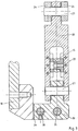
- the coupling linkage 14 has a push rod 15 (see also FIG. 4) which is guided in a straight line with the aid of a bearing bush 16.
- the push rod carries out a straight reciprocating movement according to arrow 17.
- a rocker arm 20 is provided on the housing or frame 18 in a bearing block 19 as an integral part of the coupling linkage 14.
- a joint 21 is arranged, via which the rocker arm 20 is connected to the bearing block 19.
- a central bearing 22 is formed, via which the front end of the push rod 15 articulates on the rocker arm 20.
- This central bearing 22 is arranged in the main direction of extension of the rocker arm 20 so as to be displaceable by the required amount, as can be seen in particular in FIG. This displaceability is necessary because the push rod 15 executes a straight-line reciprocating movement, while the rocker arm 20 executes an arc-shaped movement around the joint 21.
- a joint 23 is provided, on which a transmission lever 24 engages, which also still belongs to the coupling linkage 14.
- the gear connection is supplemented by a clamping lever 25, which is clamped in a rotationally fixed manner on the rotary slide 4 with the aid of a feather key 26, namely laterally on a shaft-like extension 27.
- the clamping lever 25 extends radially to the axis of the rotary slide 4.
- the clamping lever 25 and the transmission lever 24 are connected by means of a joint 28. It can be seen that the reciprocating movement of the push rod 15 according to arrow 17 is converted into a reciprocating movement of the rocking lever 20 around the joint 21, this movement taking place according to arrow 29. Via the transmission lever 24 and the clamping lever 25, the rotary slide 4 is thus transmitted in the forward and backward rotary movement according to the pivoting range in the basic position 11.
Landscapes
- Engineering & Computer Science (AREA)
- Mechanical Engineering (AREA)
- General Engineering & Computer Science (AREA)
- Reciprocating Pumps (AREA)
Applications Claiming Priority (2)
| Application Number | Priority Date | Filing Date | Title |
|---|---|---|---|
| DE4136097A DE4136097C1 (fr) | 1991-11-02 | 1991-11-02 | |
| DE4136097 | 1991-11-02 |
Publications (2)
| Publication Number | Publication Date |
|---|---|
| EP0540944A1 true EP0540944A1 (fr) | 1993-05-12 |
| EP0540944B1 EP0540944B1 (fr) | 1995-03-29 |
Family
ID=6443930
Family Applications (1)
| Application Number | Title | Priority Date | Filing Date |
|---|---|---|---|
| EP92118043A Expired - Lifetime EP0540944B1 (fr) | 1991-11-02 | 1992-10-22 | Pompe doseuse pour produits à haute viscosité |
Country Status (3)
| Country | Link |
|---|---|
| US (1) | US5330331A (fr) |
| EP (1) | EP0540944B1 (fr) |
| DE (2) | DE4136097C1 (fr) |
Families Citing this family (10)
| Publication number | Priority date | Publication date | Assignee | Title |
|---|---|---|---|---|
| EP0690232A1 (fr) * | 1994-06-28 | 1996-01-03 | MTA Automation AG | Pompe à membrane |
| US5741261A (en) * | 1996-06-25 | 1998-04-21 | Sdgi Holdings, Inc. | Minimally invasive spinal surgical methods and instruments |
| GB2374039B (en) * | 2001-02-24 | 2005-08-03 | P O Marketing Ltd | A personalisable presentation item |
| DE102005024174A1 (de) * | 2005-05-23 | 2006-12-07 | Schwing, Friedrich, Dipl.-Ing. | Verfahren zum Steuern einer Pumpvorrichtung zur Förderung breiiger Massen sowie Steuerung einer Pumpvorrichtung zur Förderung breiiger Massen |
| US9579429B2 (en) * | 2006-03-29 | 2017-02-28 | Novartis Ag | Surgical cassette with compliant clamping zone |
| US7712802B2 (en) * | 2006-06-12 | 2010-05-11 | Alcon, Inc. | Cassette clamping mechanism |
| US20080015515A1 (en) * | 2006-06-29 | 2008-01-17 | Mark Alan Hopkins | Top and bottom clamping for a surgical cassette |
| EP2133609B1 (fr) * | 2008-06-13 | 2013-01-23 | Willcox Investments S.A. | Soupape de distribution de précision |
| BR112017007471B1 (pt) * | 2014-10-13 | 2022-09-06 | Alfa S.R.L. | Bomba de deslocamento positivo e grupo de bombeamento para produtos fluidos e método para o uso dos mesmos |
| US11035348B2 (en) * | 2018-08-28 | 2021-06-15 | National Oilwell Varco, L.P. | Reciprocating pumps having a pivoting arm |
Citations (3)
| Publication number | Priority date | Publication date | Assignee | Title |
|---|---|---|---|---|
| US3421378A (en) * | 1965-09-15 | 1969-01-14 | Nikex Nehezipari Kulkere | Device for stepless variation of machine stroke length during operation |
| GB1513468A (en) * | 1975-10-07 | 1978-06-07 | Chrysler Uk | Rotor balancing devices |
| FR2644851A1 (fr) * | 1988-11-24 | 1990-09-28 | Kechich David | Pompe pour pompage des produits alimentaires liquides contenant des parties solides dont la temperature est voisine de 180 degres celsius |
Family Cites Families (10)
| Publication number | Priority date | Publication date | Assignee | Title |
|---|---|---|---|---|
| US1066660A (en) * | 1913-07-08 | Charles P Ross | Liquid-measuring apparatus. | |
| US2017975A (en) * | 1932-02-17 | 1935-10-22 | Jacobus C Kooyman | Concrete pump |
| US2032163A (en) * | 1932-09-30 | 1936-02-25 | Ralph B Bagby | Filling machine |
| US2125283A (en) * | 1936-05-06 | 1938-08-02 | Leo S Madlem | Pump for semifluids |
| US2384783A (en) * | 1943-09-23 | 1945-09-11 | Chain Belt Co | Pump for plastic concrete mixtures |
| US2448104A (en) * | 1945-12-06 | 1948-08-31 | Chain Belt Co | Differential concrete pump |
| DE1010377B (de) * | 1954-09-06 | 1957-06-13 | Lewa O H G Ott & Schestag | Dosierpumpe fuer Fluessigkeiten |
| DE1013519B (de) * | 1955-09-19 | 1957-08-08 | Lewa O H G Ott & Schestag | Dosierpumpe fuer Fluessigkeiten |
| US3506382A (en) * | 1968-05-21 | 1970-04-14 | Zurcon Corp | Concrete pump |
| US3552440A (en) * | 1969-01-09 | 1971-01-05 | Hercules Concrete Pumps Inc | Valve for controlling flow of concrete |
-
1991
- 1991-11-02 DE DE4136097A patent/DE4136097C1/de not_active Expired - Fee Related
-
1992
- 1992-10-22 DE DE59201773T patent/DE59201773D1/de not_active Expired - Fee Related
- 1992-10-22 EP EP92118043A patent/EP0540944B1/fr not_active Expired - Lifetime
- 1992-11-02 US US07/970,258 patent/US5330331A/en not_active Expired - Fee Related
Patent Citations (3)
| Publication number | Priority date | Publication date | Assignee | Title |
|---|---|---|---|---|
| US3421378A (en) * | 1965-09-15 | 1969-01-14 | Nikex Nehezipari Kulkere | Device for stepless variation of machine stroke length during operation |
| GB1513468A (en) * | 1975-10-07 | 1978-06-07 | Chrysler Uk | Rotor balancing devices |
| FR2644851A1 (fr) * | 1988-11-24 | 1990-09-28 | Kechich David | Pompe pour pompage des produits alimentaires liquides contenant des parties solides dont la temperature est voisine de 180 degres celsius |
Non-Patent Citations (1)
| Title |
|---|
| CHIRONIS 'Mechanisms, linkages and mechanical controls' 1965 , MCGRAW-HILL , NEW-YORK Adjustable-pivot drive * |
Also Published As
| Publication number | Publication date |
|---|---|
| US5330331A (en) | 1994-07-19 |
| DE4136097C1 (fr) | 1993-03-04 |
| DE59201773D1 (de) | 1995-05-04 |
| EP0540944B1 (fr) | 1995-03-29 |
Similar Documents
| Publication | Publication Date | Title |
|---|---|---|
| DE69920720T2 (de) | Betätigungsvorrichtung für die öffnung eines spritzgussventils | |
| DE2104191C3 (de) | Vorrichtung zur Förderung von breiigen, abbindenden Massen | |
| EP3031774B1 (fr) | Soupape de remplissage d'un recipient avec un produit de remplissage | |
| EP0540944B1 (fr) | Pompe doseuse pour produits à haute viscosité | |
| DE2017476C3 (de) | Schließvorrichtung für eine an Führungen bewegbare Werkzeugträgerplatte an Spritzgießmaschinen | |
| DE2447054B2 (de) | Zuteilvorrichtung für eine Betonpumpe | |
| DE2636165A1 (de) | Anlage zum steuern von stroemungsmengenverhaeltnissen | |
| DE4440243A1 (de) | Dosier-Gerät für viskose Materialien | |
| EP0736333B1 (fr) | Dispositif manuel d'extrusion de produit pâteux | |
| DE2929205C2 (fr) | ||
| DE2341585A1 (de) | Einhand-einloch-mischbatterie | |
| DE2032717A1 (de) | Maschine zum Portionieren und Abfüllen von flussigen oder pastosen Massen | |
| DE682115C (de) | Spritzgussmaschine zum Verarbeiten waermeplastischer Massen | |
| EP0394790B1 (fr) | Dispositif pour la fabrication d'un mélange réactif apte à couler à partir d'au moins deux composants réactifs aptes à couler pour la fabrication de matières plastiques massives ou cellulaires | |
| DE4344922C2 (de) | Vorrichtung zum Befüllen einer oder mehrerer Gießformen mit gießfähig flüssigen Medien | |
| DE1139286B (de) | Dosierpumpe | |
| DE1604530B2 (de) | Vorrichtung zum Ausstoßen einer einstellbaren, genau dosierten Menge der Komponenten eines flüssigen Mehrkomponnten-Kunststoffes | |
| DE203105C (fr) | ||
| DE1266732B (de) | Verschliesseinrichtung fuer die Entleerungsoeffnung einer Misch- und Knetvorrichtung | |
| DE2227515C3 (de) | Vorrichtung zum dosierten Zuführen einer flüssigen Kunststoffkomponente in eine Mischkammer | |
| DE3509294A1 (de) | Vorrichtung zum dosieren von hochviskosen fluessigkeiten und/oder massen | |
| DE10120999A1 (de) | Antriebsvorrichtung für die bewegliche Formaufspannplatte einer Spritzgießmaschine | |
| DE2342098C3 (de) | Hydraulische Presse mit zwei Endschaltern und einem von der Lage des Stößels gesteuerten Potentiometer | |
| WO2020083605A1 (fr) | Pompe à piston à transport continu | |
| DE4117541A1 (de) | Dosierpumpe fuer hochviskoses fuellgut |
Legal Events
| Date | Code | Title | Description |
|---|---|---|---|
| PUAI | Public reference made under article 153(3) epc to a published international application that has entered the european phase |
Free format text: ORIGINAL CODE: 0009012 |
|
| AK | Designated contracting states |
Kind code of ref document: A1 Designated state(s): CH DE FR GB IT LI NL |
|
| 17P | Request for examination filed |
Effective date: 19930517 |
|
| 17Q | First examination report despatched |
Effective date: 19940712 |
|
| ITF | It: translation for a ep patent filed |
Owner name: DE DOMINICIS & MAYER S.R.L. |
|
| GRAA | (expected) grant |
Free format text: ORIGINAL CODE: 0009210 |
|
| AK | Designated contracting states |
Kind code of ref document: B1 Designated state(s): CH DE FR GB IT LI NL |
|
| GBT | Gb: translation of ep patent filed (gb section 77(6)(a)/1977) |
Effective date: 19950328 |
|
| REF | Corresponds to: |
Ref document number: 59201773 Country of ref document: DE Date of ref document: 19950504 |
|
| ET | Fr: translation filed | ||
| PGFP | Annual fee paid to national office [announced via postgrant information from national office to epo] |
Ref country code: FR Payment date: 19951017 Year of fee payment: 4 |
|
| PGFP | Annual fee paid to national office [announced via postgrant information from national office to epo] |
Ref country code: NL Payment date: 19951020 Year of fee payment: 4 Ref country code: DE Payment date: 19951020 Year of fee payment: 4 |
|
| PGFP | Annual fee paid to national office [announced via postgrant information from national office to epo] |
Ref country code: CH Payment date: 19951023 Year of fee payment: 4 |
|
| PLBE | No opposition filed within time limit |
Free format text: ORIGINAL CODE: 0009261 |
|
| STAA | Information on the status of an ep patent application or granted ep patent |
Free format text: STATUS: NO OPPOSITION FILED WITHIN TIME LIMIT |
|
| 26N | No opposition filed | ||
| PG25 | Lapsed in a contracting state [announced via postgrant information from national office to epo] |
Ref country code: GB Effective date: 19961022 |
|
| PG25 | Lapsed in a contracting state [announced via postgrant information from national office to epo] |
Ref country code: LI Effective date: 19961031 Ref country code: CH Effective date: 19961031 |
|
| PG25 | Lapsed in a contracting state [announced via postgrant information from national office to epo] |
Ref country code: NL Effective date: 19970501 |
|
| GBPC | Gb: european patent ceased through non-payment of renewal fee |
Effective date: 19961022 |
|
| REG | Reference to a national code |
Ref country code: CH Ref legal event code: PL |
|
| PG25 | Lapsed in a contracting state [announced via postgrant information from national office to epo] |
Ref country code: FR Effective date: 19970630 |
|
| NLV4 | Nl: lapsed or anulled due to non-payment of the annual fee |
Effective date: 19970501 |
|
| PG25 | Lapsed in a contracting state [announced via postgrant information from national office to epo] |
Ref country code: DE Effective date: 19970701 |
|
| REG | Reference to a national code |
Ref country code: FR Ref legal event code: ST |
|
| PG25 | Lapsed in a contracting state [announced via postgrant information from national office to epo] |
Ref country code: IT Free format text: LAPSE BECAUSE OF NON-PAYMENT OF DUE FEES;WARNING: LAPSES OF ITALIAN PATENTS WITH EFFECTIVE DATE BEFORE 2007 MAY HAVE OCCURRED AT ANY TIME BEFORE 2007. THE CORRECT EFFECTIVE DATE MAY BE DIFFERENT FROM THE ONE RECORDED. Effective date: 20051022 |