EP0540944A1 - Metering pump for viscous products - Google Patents
Metering pump for viscous products Download PDFInfo
- Publication number
- EP0540944A1 EP0540944A1 EP92118043A EP92118043A EP0540944A1 EP 0540944 A1 EP0540944 A1 EP 0540944A1 EP 92118043 A EP92118043 A EP 92118043A EP 92118043 A EP92118043 A EP 92118043A EP 0540944 A1 EP0540944 A1 EP 0540944A1
- Authority
- EP
- European Patent Office
- Prior art keywords
- rocker arm
- rotary valve
- rotary
- drive
- bearing block
- Prior art date
- Legal status (The legal status is an assumption and is not a legal conclusion. Google has not performed a legal analysis and makes no representation as to the accuracy of the status listed.)
- Granted
Links
Images


Classifications
-
- F—MECHANICAL ENGINEERING; LIGHTING; HEATING; WEAPONS; BLASTING
- F04—POSITIVE - DISPLACEMENT MACHINES FOR LIQUIDS; PUMPS FOR LIQUIDS OR ELASTIC FLUIDS
- F04B—POSITIVE-DISPLACEMENT MACHINES FOR LIQUIDS; PUMPS
- F04B15/00—Pumps adapted to handle specific fluids, e.g. by selection of specific materials for pumps or pump parts
- F04B15/02—Pumps adapted to handle specific fluids, e.g. by selection of specific materials for pumps or pump parts the fluids being viscous or non-homogeneous
-
- F—MECHANICAL ENGINEERING; LIGHTING; HEATING; WEAPONS; BLASTING
- F04—POSITIVE - DISPLACEMENT MACHINES FOR LIQUIDS; PUMPS FOR LIQUIDS OR ELASTIC FLUIDS
- F04B—POSITIVE-DISPLACEMENT MACHINES FOR LIQUIDS; PUMPS
- F04B7/00—Piston machines or pumps characterised by having positively-driven valving
- F04B7/0003—Piston machines or pumps characterised by having positively-driven valving the distribution member forming both the inlet and discharge distributor for one single pumping chamber
- F04B7/0011—Piston machines or pumps characterised by having positively-driven valving the distribution member forming both the inlet and discharge distributor for one single pumping chamber and having an oscillating movement
-
- Y—GENERAL TAGGING OF NEW TECHNOLOGICAL DEVELOPMENTS; GENERAL TAGGING OF CROSS-SECTIONAL TECHNOLOGIES SPANNING OVER SEVERAL SECTIONS OF THE IPC; TECHNICAL SUBJECTS COVERED BY FORMER USPC CROSS-REFERENCE ART COLLECTIONS [XRACs] AND DIGESTS
- Y10—TECHNICAL SUBJECTS COVERED BY FORMER USPC
- Y10S—TECHNICAL SUBJECTS COVERED BY FORMER USPC CROSS-REFERENCE ART COLLECTIONS [XRACs] AND DIGESTS
- Y10S417/00—Pumps
- Y10S417/90—Slurry pumps, e.g. concrete
Abstract
Eine Dosierpumpe für hochviskoses Füllgut weist einen kurbelwellenähnlichen Antrieb für ein hin- und hergehende Bewegung eines Kolbens (1) in einem Zylinder (2) und einen davon abgeleiteten Antrieb für eine vor- und zurückgehende Drehbewegung eines Drehschiebers (4) auf. Der Drehschieber (4) besitzt Durchbrechungen und dessen Gehäuse Anschlüsse für eine Saugleitung (7) und eine Auslaßleitung (8) der Kolben/Zylinder-Einheit (1, 2). Für die Drehbewegung des Drehschiebers (4) ist eine Steuerscheibe, ein Koppelgestänge (14) und ein am Drehschieber (4) angreifender Klemmhebel (25) vorgesehen. Das Koppelgestänge (14) weist einen Schwinghebel (20) auf, an dessen einem Ende ein Gelenk (21) gebildet ist, das an einem ortsfesten und verschiebbar angeordneten Lagerbock (19) gebildet ist. Es ist ein Stelltrieb (30) für die Veränderung der Lage des Lagerbocks (19) unabhängig vom kurbelwellenähnlichen Antrieb vorgesehen. <IMAGE>A metering pump for highly viscous filling material has a crankshaft-like drive for a reciprocating movement of a piston (1) in a cylinder (2) and a drive derived therefrom for a forward and backward rotary movement of a rotary valve (4). The rotary valve (4) has openings and its housing connections for a suction line (7) and an outlet line (8) of the piston / cylinder unit (1, 2). A control disk, a coupling linkage (14) and a clamping lever (25) acting on the rotary valve (4) are provided for the rotary movement of the rotary valve (4). The coupling linkage (14) has a rocker arm (20), at one end of which a joint (21) is formed, which is formed on a stationary and displaceably arranged bearing block (19). An actuator (30) is provided for changing the position of the bearing block (19) independently of the crankshaft-like drive. <IMAGE>
Description
Die Erfindung bezieht sich auf eine Dosierpumpe für hochviskoses Füllgut, mit einem kurbelwellenähnlichen Antrieb für eine hin-und hergehende Bewegung eines Kolbens in einem Zylinder und einem davon abgeleiteten Antrieb für eine vor- und zurückgehende Drehbewegung eines Drehschiebers, wobei der Drehschieber Durchbrechungen und dessen Gehäuse Anschlüsse für eine Saugleitung und eine Auslaßleitung der Kolben/Zylinder-Einheit aufweist und für die Drehbewegung des Drehschiebers eine Steuerscheibe, ein Koppelgestänge und ein am Drehschieber angreifender Klemmhebel vorgesehen sind. Insbesondere bezieht sich die Erfindung auf eine Dosierpumpe zum Einbringen entsprechender Portionsmengen in einen Folienstrang mit in dichter Reihenfolge angesiedelten Kammern. Unter einem hochviskosen Füllgut werden dickflüssige Produkte, Pasten u. dgl. verstanden, beispielsweise Ketchup, Senf, kosmetische Produkte, Zahnpasta usw.The invention relates to a metering pump for highly viscous contents, with a crankshaft-like drive for a reciprocating movement of a piston in a cylinder and a drive derived therefrom for a back and forth rotary movement of a rotary valve, the rotary valve having openings and its housing connections for a suction line and an outlet line of the piston / cylinder unit and for the rotary movement of the rotary valve a control disk, a coupling linkage and a clamping lever acting on the rotary valve are provided. In particular, the invention relates to a metering pump for introducing appropriate portion amounts into a film strand with chambers located in tight order. Under a highly viscous product, viscous products, pastes etc. The like understood, for example ketchup, mustard, cosmetic products, toothpaste, etc.
Es ist eine Dosierpumpe der eingangs beschriebenen Art bekannt, bei der das Koppelgestänge einen Übertragungshebel aufweist, der am Klemmhebel angreift. Der Klemmhebel sitzt radial auf dem Drehschieber. Der Übertragungshebel ist längenveränderlich ausgebildet. Zu diesem Zweck ist er unterteilt und mit entsprechenden Gewindestücken versehen. Der Klemmhebel greift unter Verwendung einer Paßfeder an dem Drehschieber an, so daß die radiale Lage des Klemmhebels zum Drehschieber und dessen Durchbrechungen nicht veränderbar ist. Die Länge des Übertragungshebels kann nur während des Stillstands der Dosierpumpe verändert werden. Mit der Veränderung der Länge des Übertragungshebels wird die Lage des Drehwinkels, den der Klemmhebel und der Drehschieber bei der vor- und zurückgehenden Drehbewegung durchlaufen, verändert, während die Größe dieses Winkels, die im allgemeinen 90° beträgt, bei einer solchen Verstellung in etwa gleichbleibt. Eine solche Verstellung der Lage des Drehwinkels, die nur beim Stillstand der Dosierpumpe durchgeführt werden kann, ist umständlich und nachteilig. Bei jedem einzelnen Einstell- bzw. Nachjustiergang muß die Dosierpumpe stillgesetzt, d. h. der Abfüllvorgang unterbrochen werden. Das Gehäuse der Dosierpumpe muß an der entsprechenden Stelle geöffnet werden, damit der Übertragungshebel zugänglich wird. Die Längenveränderung kann dann vorgenommen werden. Erst, wenn der Abfüllvorgang wieder aufgenommen worden ist, ist ersichtlich, ob die Einstellung das gewünschte Ergebnis erbracht hat oder nicht. Ist dies nicht der Fall, muß der gesamte Einstellvorgang wiederholt werden. Ändert sich die Viskosität des Füllguts während des Abfüllvorgangs, was durchaus vorkommen kann, so ist eine Nachjustierung bei der bekannten Dosierpumpe praktisch nicht möglich. Ein solches Nachjustieren ist jedoch in vielen Fällen beim Abfüllvorgang schwierig zu handhabender Füllgüter sehr erwünscht bzw. unerläßlich. Da der Drehschieber gleichsam als Ventil wirkt, um im Saughub den Füllbehälter des Füllguts mit der Kolben/Zylinder-Einheit zu verbinden und im Ausstoßhub diese Verbindung abzusperren sowie den Raum der Kolben/Zylinder-Einheit mit der Auslaßleitung zu verbinden, werden sich immer solche Verhältnisse ergeben, daß der Strang des Füllguts im Endbereich der Auslaßleitung, also bereits jenseits des Drehschiebers, abreißen muß, um die jeweilige Portion zu ergeben. Es ist bekannt, zu Beginn des Saughubs der Kolben/Zylinder-Einheit aus der Auslaßleitung Füllgut zurückzusaugen, welches sich dann entgegengerichtet zu der abzugebenden Portion, auf die die Schwerkraft einwirkt, in der Auslaßleitung nach oben bzw. rückwärts bewegt. Diese beiden gegenläufigen Bewegungen sollen einen sauberen Abriß des Füllguts nach jeder Portion erbringen. Je nach Füllgut muß dieser Rücksaugeffekt unterschiedlich eingestellt werden und in vielen Fällen nachjustiert werden, damit ein solcher sauberer Abriß des Füllguts erreicht wird und nicht Spuren von Füllgut beispielsweise auf die zu siegelnde Fläche des Verpackungsbehälters für das Füllgut gelangen, wo sie die Siegelung stören würden. Da bei solchen Dosierpumpen auch das Füllvolumen einstellbar sein muß, ist die zusätzliche Schwierigkeit gegeben, da sich mit der Verstellung des Füllvolumens auch wiederum die Verhältnisse am Abriß des Füllgutstrangs ändern. Hier ist eine relative Einstellung notwendig. Es wird erkennbar, daß diese Einstellmöglichkeiten bei der bekannten Dosierpumpe unbefriedigend sind.A metering pump of the type described at the outset is known, in which the coupling linkage has a transmission lever which acts on the clamping lever. The clamping lever sits radially on the rotary valve. The transmission lever is variable in length. For this purpose, it is subdivided and provided with corresponding threaded pieces. The clamping lever engages the rotary valve using a feather key, so that the radial position of the clamping lever relative to the rotary valve and its openings cannot be changed. The length of the transmission lever can only be changed while the dosing pump is at a standstill. With the change in the length of the transmission lever, the position of the angle of rotation through which the clamping lever and the rotary valve pass during the forward and backward rotary movement is changed, while the size of this angle, which is generally 90 °, with such an adjustment in about the same. Such an adjustment of the position of the angle of rotation, which can only be carried out when the metering pump is at a standstill, is cumbersome and disadvantageous. With each individual adjustment or readjustment cycle, the metering pump must be stopped, ie the filling process must be interrupted. The housing of the metering pump must be opened at the appropriate point so that the transmission lever is accessible. The length can then be changed. Only when the filling process has been restarted can you see whether the setting has produced the desired result or not. If this is not the case, the entire setting process must be repeated. If the viscosity of the filling material changes during the filling process, which may well occur, it is practically impossible to readjust the known metering pump. Such readjustment is, however, very desirable or indispensable in many cases during the filling process of filling goods which are difficult to handle. Since the rotary valve acts as a valve to connect the filling container of the filling material with the piston / cylinder unit in the suction stroke and to shut off this connection in the exhaust stroke and to connect the space of the piston / cylinder unit with the outlet line, there will always be such conditions show that the strand of the filling material must tear off in the end region of the outlet line, that is to say beyond the rotary slide valve, in order to give the respective portion. It is known at the beginning of the suction stroke of the piston / cylinder unit to suck back filling material from the outlet line, which then moves in the opposite direction to the portion to be dispensed, which is affected by gravity, in the outlet line upwards or backwards. These two opposing movements are intended to ensure that the filling is torn off cleanly after each serving. Depending on the filling material, this sucking back effect must be set differently and readjusted in many cases so that such a clean tearing off of the filling material is achieved and not traces of filling material, for example, on the surface to be sealed Packaging container for the filling material get where they would interfere with the sealing. Since the filling volume must also be adjustable in the case of such metering pumps, the additional difficulty is present since, with the adjustment of the filling volume, the conditions at the break of the filling material strand also change. A relative setting is necessary here. It can be seen that these setting options are unsatisfactory in the known metering pump.
Der Erfindung liegt die Aufgabe zugrunde, eine Dosierpumpe der eingangs beschriebenen Art derart weiterzubilden, daß die Lage des Drehwinkels des Drehschiebers und damit die Verhältnisse beim Abriß des Füllgutstrangs während des Laufs der Dosierpumpe veränderbar sind. Dies gilt sowohl für eine Grundeinstellung, die sich beispielsweise nach der Art des Füllguts richtet wie auch für eine Nachjustierung, wie sie beispielsweise bei Viskositätsänderungen des Füllguts auftreten.The invention has for its object to develop a metering pump of the type described in such a way that the position of the angle of rotation of the rotary valve and thus the conditions when the filling material strand is torn off while the metering pump is running can be changed. This applies both to a basic setting, which depends, for example, on the type of the filling material, and to a readjustment, such as occurs, for example, when the viscosity of the filling material changes.
Erfindungsgemäß wird dies bei der Dosierpumpe der eingangs beschriebenen Art dadurch erreicht, daß das Koppelgestänge einen Schwinghebel aufweist, an dessen einem Ende ein Gelenk gebildet ist, das an einem verschiebbar angeordneten Lagerbock gelagert ist, und daß ein Stelltrieb für die Veränderung der Lage des Lagerbocks unabhängig vom kurbelwellenähnlichen Antrieb vorgesehen ist. Wesentlicher Bestandteil des Koppelgestänges ist ein Schwinghebel, wobei unter einem solchen Schwinghebel ein Hebel verstanden wird, der um ein an seinem einen Ende vorgesehenes Gelenk zeigerartig hin- und herschwingt. Die übrigen Bestandteile des Koppelgestänges greifen nicht an diesem Gelenk, sondern einerseits am anderen Ende des Schwinghebels und weiterhin irgendwo in der Mitte des Schwinghebels an. Damit eröffnet sich die Möglichkeit, die ortsfeste Lage des Gelenks, um welches der Schwinghebel schwingt, zu verändern. Der dazu an diesem Gelenk angreifende Stelltrieb befindet sich am Gehäuse der Dosierpumpe in Ruhe, macht also die Bewegung des Koppelgestänges nicht mit. Damit ist es möglich, den Stelltrieb aus dem Gehäuse der Dosierpumpe herauszuführen und beispielsweise mit Hilfe eines Handrads feinfühlig verdrehbar zu gestalten, und zwar während des Betriebs der Dosierpumpe. Gleichzeitig erbringt ein solcher Schwinghebel den zusätzlichen Vorteil, daß mit ihm eine Übersetzung erzielt wird. Das Gelenk bzw. der Lagerbock, um welchen der Schwinghebel hin- und herschwingt, muß nur um eine relativ kleine Strecke verschoben werden, um die Lage des Drehwinkels entsprechend der Übersetzung des Schwinghebels verstellen zu können. Der wesentliche Vorteil einer solchen Verstellung ist darin zu sehen, daß er während des Betriebs der Dosierpumpe genutzt werden kann, und daß dabei das Arbeitsergebnis sofort überprüfbar ist. Zweckmäßige Nachjustierungen, die beim Stand der Technik unterbleiben, können ohne Weiteres durchgeführt werden. Damit ist eine bessere und vor allen Dingen schnellere Anpaßbarkeit an die verschiebenen Parameter des Füllguts möglich. Es wird ein Teil des Saughubs der Dosierpumpe zu Beginn des Saughubs dazu genutzt, um den Füllgutstrang in der Auslaßleitung hoch- bzw. zurückzuziehen, um einen sauberen, reproduzierbaren Abriß des Füllguts zu erreichen und ein Nachkleckern von Füllgut zu vermeiden.According to the invention this is achieved in the metering pump of the type described in the introduction in that the coupling linkage has a rocker arm, at one end of which a joint is formed which is mounted on a displaceably arranged bearing block, and in that an actuator for changing the position of the bearing block is independent is provided by the crankshaft-like drive. An essential component of the coupling linkage is a rocker arm, whereby such a rocker arm is understood to mean a lever which swings back and forth like a pointer around a joint provided at one end. The remaining components of the coupling linkage do not act on this joint, but on the one hand on the other end of the rocker arm and still somewhere in the middle of the rocker arm. This opens up the possibility of changing the fixed position of the joint around which the rocker arm swings. The actuator that acts on this joint is located on the housing the dosing pump at rest, does not follow the movement of the coupling linkage. This makes it possible to lead the actuator out of the housing of the metering pump and, for example, to turn it with the help of a handwheel, during the operation of the metering pump. At the same time, such a rocker arm has the additional advantage that a translation is achieved with it. The joint or the bearing block around which the rocker arm swings back and forth only has to be moved a relatively small distance in order to be able to adjust the position of the angle of rotation in accordance with the translation of the rocker arm. The main advantage of such an adjustment can be seen in the fact that it can be used during the operation of the metering pump and that the work result can be checked immediately. Appropriate readjustments that are omitted in the prior art can be carried out without further ado. This enables better and, above all, faster adaptability to the shifting parameters of the product. Part of the suction stroke of the metering pump at the beginning of the suction stroke is used to pull the product line up or down in the outlet line in order to achieve a clean, reproducible tearing off of the product and to avoid re-spilling of the product.
Im Einzelnen kann das Koppelgestänge eine an der Steuerscheibe angreifende Schubstange, den Schwinghebel und einen am Klemmhebel angelenkten Übertragungshebel aufweisen, wobei die Schubstange gelenkig am Mittellager des Schwinghebels angreift; das andere endseitige Gelenk des Schwinghebels ist dann am Übertragungshebel angelenkt. Damit wird ein einfaches Koppelgestänge geschaffen, welches die beschriebene Einstellbarkeit und Nachstellbarkeit während des Betriebs der Dosierpumpe erbringt. Ein solches Koppelgestänge ist für eine Dosierpumpe geeignet, bei der eine Steuerscheibe, auf der Antriebswelle sitzend, zur Anwendung kommt, wobei das eine Ende der Schubstange seine hin- und hergehende Bewegung von dem exzentrisch ausgebildeten Umfang oder einer Gleitnut der Steuerscheibe abnimmt.In detail, the coupling linkage can have a push rod engaging on the control disk, the rocking lever and a transmission lever articulated on the clamping lever, the push rod pivoting on the central bearing of the rocking lever; the other end joint of the rocker arm is then articulated on the transmission lever. This creates a simple coupling linkage, which provides the described adjustability and adjustability during operation of the metering pump. Such a coupling linkage is suitable for a metering pump in which a control disk, seated on the drive shaft, is used, with one end of the push rod moving its back and forth Moving movement decreases from the eccentrically formed circumference or a sliding groove of the control disc.
Der Lagerbock kann auf einer Führungsstange verschiebbar und über eine Steuerspindel als Bestandteil des Stelltriebs vermittels eines Gewindes verstellbar sein. Die Achsen der Führungsstange und der Steuerspindel sind parallel zueinander angeordnet. Sie durchdringen beide den Lagerbock, so daß dieser verdrehgesichert ortsfest gelagert und trotzdem linear verschiebbar ist. Es ist natürlich auch möglich, den Lagerbock in einem Gleitbett zu führen und allein über eine Steuerspindel zu verschieben.The bearing block can be displaced on a guide rod and can be adjusted by means of a thread via a control spindle as part of the actuator. The axes of the guide rod and the control spindle are arranged parallel to each other. They both penetrate the bearing block, so that it is non-rotatably mounted and nonetheless linearly displaceable. It is of course also possible to guide the bearing block in a sliding bed and to move it using a control spindle alone.
Die Schubstange kann zweckmäßig geradlinig geführt sein und ihr im Mittelbereich des Schwenkhebel angreifendes Mittellager ist dann in Erstreckungsrichtung des Schwinghebels auf diesem verschiebbar angeordnet. Diese Verschiebbarkeit ist erforderlich, weil der Schwinghebel auch in seinem Mittelbereich eine Kreisbogenbewegung ausführt, während die Schubstange geradlinig geführt ist. Die hierdurch bewirkten Unterschiede werden damit ausgeglichen.The push rod can be expediently guided in a straight line, and its central bearing, which engages in the central region of the swivel lever, is then displaceably arranged on the swivel lever in the direction of extension. This displaceability is necessary because the rocker arm also executes a circular arc movement in its central region, while the push rod is guided in a straight line. The differences caused by this are thus compensated.
Ein bevorzugtes Ausführungsbeispiel der Dosierpumpe mit den für die Erfindung wesentlichen Teilen ist in den Zeichnungen dargestellt und wird im Folgenden beschrieben. Es zeigen:
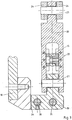
Figur 1- einen Vertikalschnitt durch den Drehschieber und die anschließende Kolben/Zylinder-Einheit der Dosierpumpe,
Figur 2- eine Seitenansicht wesentlicher Teile des Koppelgestänges,
Figur 3- einen Schnitt gemäß der Linie III-III in
Figur 2 und Figur 4- einen Schnitt gemäß der Linie IV-IV in
Figur 2.
- Figure 1
- a vertical section through the rotary slide valve and the subsequent piston / cylinder unit of the metering pump,
- Figure 2
- a side view of essential parts of the coupling linkage,
- Figure 3
- a section along the line III-III in Figure 2 and
- Figure 4
- a section along the line IV-IV in Figure 2.
In Figur 1 ist ein Kolben 1 dargestellt, der in einem Zylinder gemäß Pfeil 3 hin- und hergehend angetrieben wird. Hierzu ist ein kurbelwellenähnlicher Antrieb vorgesehen, der jedoch nicht dargestellt ist. Der Kolben ist seiner vorderen Totpunktslage gezeigt, also am Ende des Ausstoßhubs bzw. zu Beginn des Rückhubs. Die Kolben/Zylinder-Einheit 1, 2 stellt damit einen Saug- bzw. Verdrängungsraum zur Verfügung, der die Pumpwirkung erbringt.In Figure 1, a
Der Kolben/Zylinder-Einheit 1, 2 ist ein Drehschieber 4 zugeordnet, der wellenartig ausgebildet ist und in einem Gehäuse 5 verdrehbar gelagert ist. Der Drehschieber 4 ist von T-förmig angeordneten Durchbrechungen 6 durchsetzt, die sich radial zur Achse des Drehschiebers 4 erstrecken. Am Gehäuse 5 des Drehschiebers 4 ist oben eine Saugleitung 7 angeschlossen, während seitlich eine Auslaßleitung 8 beginnt. Die Saugleitung 7 steht mit einem Vorratsbehälter für Füllgut in Verbindung, so daS während des Saughubs der Kolben/Zylinder-Einheit 1, 2 Füllgut gemäß Pfeil 9 durch die dann anschließenden Durchbrechungen 6 in den sich bildenden Raum zwischen Kolben 1 und Zylinder 2 gelangen kann. Während des Ausstoßhubs befindet sich der Drehschieber 4 jedoch in der in Figur 1 dargestellten Stellung, bei der die Saugleitung 7 abgeschlossen ist, so daß Füllgut durch die Durchbrechungen 6 in die Auslaßleitung 8 und ein dort anschließendes, nicht dargestelltes Füllrohr gemäß Pfeil 10 an eine Abgabestelle in der vorgesehenen Portionsgröße transportiert wird. Am Ende dieses Füllrohrs findet dann der beschriebene Abreißvorgang des Füllguts statt. Um diesen Abreißvorgang zu begünstigen, verbleibt der Drehschieber 4 in der in Figur 1 dargestellten Stellung für einen gewissen Bereich zu Beginn des Saughubs der Kolben/Zylinder-Einheit 1, 2, damit das Füllgut in der Fülleitung entgegengerichtet dem Pfeil 10 hochgesogen wird. Damit wird zugleich ein Nachkleckern von Füllguttropfen vermieden.The piston /
Es ist erkennbar, daß der Drehschieber 4 vor- und zurückgehend eine Drehbewegung um etwa 90° ausführen muß. In Figur 2 ist dieser Schwenkbereich in seiner Grundeinstellung 11 dargestellt. Es ist ein Verstellbereich 12 verdeutlicht, der hier etwa 15° betragen kann. Damit ist ersichtlich, daß der Schwenkbereich 11 in seiner relativen Lage etwa um den Verstellbereich 12 maximal verändert werden kann. Der maximal veränderte Schwenkbereich 13 ist die Lage des Verschwenkwinkels, bei der der maximale Rücksog des Füllguts entgegen dem Pfeil 10 erreicht wird.It can be seen that the
Für die vor- und zurückgehende Drehbewegung des Drehschiebers 4 ist in den Antriebsstrang ein Koppelgestänge 14 eingeschaltet. Das Koppelgestänge 14 weist eine Schubstange 15 auf (siehe auch Figur 4), die mit Hilfe einer Lagerbuchse 16 geradlinig geführt ist. Die Schubstange führt eine geradlinige hin- und hergehende Bewegung gemäß Pfeil 17 aus.A
An dem Gehäuse bzw. Rahmen 18 ist in einem Lagerbock 19 als wesentlicher Bestandteil des Koppelgestänges 14 ein Schwinghebel 20 vorgesehen. Am einen Ende des Schwinghebels 20 ist ein Gelenk 21 angeordnet, über welches der Schwinghebel 20 mit dem Lagerbock 19 in Verbindung steht. Im Mittelbereich des Schwinghebels ist ein Mittellager 22 gebildet, über welches das vordere Ende der Schubstange 15 gelenkig am Schwinghebel 20 angreift. Dieses Mittellager 22 ist in der Haupterstreckungsrichtung des Schwinghebels 20 um den erforderlichen Betrag verschiebbar angeordnet, wie insbesondere Figur 3 erkennen läßt. Diese Verschieblichkeit ist erforderlich, weil die Schubstange 15 eine geradlinie hin- und hergehende Bewegung ausführt, während der Schwinghebel 20 um das Gelenk 21 eine kreisbogenförmige Bewegung ausführt. An dem dem Gelenk 21 abgekehrten Ende des Schwinghebels 20 ist ein Gelenk 23 vorgesehen, an dem ein Übertragungshebel 24 angreift, der ebenfalls noch zu dem Koppelgestänge 14 gehört. Die getriebliche Verbindung wird ergänzt durch einen Klemmhebel 25, der mit Hilfe einer Paßfeder 26 drehfest auf dem Drehschieber 4, und zwar seitlich auf einem wellenähnlichen Fortsatz 27, aufgeklemmt ist. Der Klemmhebel 25 erstreckt sich radial zu der Achse des Drehschiebers 4. Der Klemmhebel 25 und der Übertragungshebel 24 sind mittels eines Gelenks 28 verbunden. Es wird erkennbar, daß die hin- und hergehende Bewegung der Schubstange 15 gemäß Pfeil 17 in eine hin-und herschwingende Bewegung des Schwinghebels 20 um das Gelenk 21 umgesetzt wird, wobei diese Bewegung gemäß Pfeil 29 erfolgt. Über den Übertragungshebel 24 und den Klemmhebel 25 wird damit der Drehschieber 4 in die vor- und zurückgehende Drehbewegung gemäß dem Schwenkbereich in der Grundstellung 11 übertragen.A
Zur Veränderung der relativen Lage dieser Grundstellung 11 im Verstellbereich 12 ist ein Stelltrieb 30 vorgesehen, der an dem Lagerbock 19 angreift und damit die relative Lage des Gelenks 21 zum Rahmen 18 verändert. Wesentlicher Bestandteil des Stelltriebs ist eine Steuerspindel 31, also eine mit Gewinde versehene Stange, die in dem Rahmen 18 drehbar gelagert ist und nach außen herausgeführt, also von dort zugänglich, in einem Drehknopf 32 endet. Der Lagerbock 19 wird nicht nur von der Steuerspindel 31 durchsetzt, sondern weiterhin noch von einer Führungsstange 33, wobei die Achsen der Steuerspindel 31 und der Führungsstange 33 parallel fluchtend zueinander angeordnet sind, so daß auf diese Art und Weise sowie durch eine Gleitfläche 34 am Rahmen 18 der Lagerbock letztendlich linear am Rahmen 18 verstellbar geführt ist. Der Verstellbereich 35 braucht nicht besonders groß zu sein. Es genügen hier etwa 4 mm für einen Verstellbereich 12 von 15°, da der Schwinghebel 20 eine entsprechende Übersetzung bewirkt. Das Gewinde der Steuerspindel 31 kann zweckmäßig ein Feingewinde sein, um eine feinfühlige Einstellung und Nachjustierung zu ermöglichen.To change the relative position of this
Figur 4 läßt erkennen, daß der Antrieb für das Koppelgestänge 14 bzw. die Schubstange 15 von einer Steuerscheibe 36 abgenommen wird, die auf einer Antriebswelle 37 sitzt, die Bestandteil des gemeinsamen Antriebs des Kolbens 1 gemäß Pfeil 3 und des Drehschiebers 4 ist. Das der Steuerscheibe 36 zugekehrte Ende der Schubstange 15 greift mit Hilfe eines Gleitsteins 38 in eine Nut 39 der Steuerscheibe 36 ein. Es versteht sich, daß die Nut 39 exzentrisch zur Achse der Antriebswelle 37 ausgebildet ist, um auf diese Art und Weise die hin- und hergehende translatorische Bewegung der Schubstange 15 gemäß Pfeil 17 abzuleiten.
Claims (4)
Applications Claiming Priority (2)
| Application Number | Priority Date | Filing Date | Title |
|---|---|---|---|
| DE4136097 | 1991-11-02 | ||
| DE4136097A DE4136097C1 (en) | 1991-11-02 | 1991-11-02 |
Publications (2)
| Publication Number | Publication Date |
|---|---|
| EP0540944A1 true EP0540944A1 (en) | 1993-05-12 |
| EP0540944B1 EP0540944B1 (en) | 1995-03-29 |
Family
ID=6443930
Family Applications (1)
| Application Number | Title | Priority Date | Filing Date |
|---|---|---|---|
| EP92118043A Expired - Lifetime EP0540944B1 (en) | 1991-11-02 | 1992-10-22 | Metering pump for viscous products |
Country Status (3)
| Country | Link |
|---|---|
| US (1) | US5330331A (en) |
| EP (1) | EP0540944B1 (en) |
| DE (2) | DE4136097C1 (en) |
Families Citing this family (10)
| Publication number | Priority date | Publication date | Assignee | Title |
|---|---|---|---|---|
| EP0690232A1 (en) * | 1994-06-28 | 1996-01-03 | MTA Automation AG | Membrane pump |
| US5741261A (en) * | 1996-06-25 | 1998-04-21 | Sdgi Holdings, Inc. | Minimally invasive spinal surgical methods and instruments |
| GB2374039B (en) * | 2001-02-24 | 2005-08-03 | P O Marketing Ltd | A personalisable presentation item |
| DE102005024174A1 (en) * | 2005-05-23 | 2006-12-07 | Schwing, Friedrich, Dipl.-Ing. | Method for controlling a pumping device for conveying mushy masses and controlling a pumping device for conveying mushy masses |
| US9579429B2 (en) * | 2006-03-29 | 2017-02-28 | Novartis Ag | Surgical cassette with compliant clamping zone |
| US7712802B2 (en) * | 2006-06-12 | 2010-05-11 | Alcon, Inc. | Cassette clamping mechanism |
| US20080015515A1 (en) * | 2006-06-29 | 2008-01-17 | Mark Alan Hopkins | Top and bottom clamping for a surgical cassette |
| EP2133609B1 (en) * | 2008-06-13 | 2013-01-23 | Willcox Investments S.A. | Precision dispense valve |
| CN107076126B (en) | 2014-10-13 | 2020-07-07 | 阿尔法有限责任公司 | Volumetric pump and pumping group for fluid products and method for using same |
| US11035348B2 (en) * | 2018-08-28 | 2021-06-15 | National Oilwell Varco, L.P. | Reciprocating pumps having a pivoting arm |
Citations (3)
| Publication number | Priority date | Publication date | Assignee | Title |
|---|---|---|---|---|
| US3421378A (en) * | 1965-09-15 | 1969-01-14 | Nikex Nehezipari Kulkere | Device for stepless variation of machine stroke length during operation |
| GB1513468A (en) * | 1975-10-07 | 1978-06-07 | Chrysler Uk | Rotor balancing devices |
| FR2644851A1 (en) * | 1988-11-24 | 1990-09-28 | Kechich David | Pump for pumping liquid food products containing solid particles whose temperature is close to 180 degrees Celsius |
Family Cites Families (10)
| Publication number | Priority date | Publication date | Assignee | Title |
|---|---|---|---|---|
| US1066660A (en) * | 1913-07-08 | Charles P Ross | Liquid-measuring apparatus. | |
| US2017975A (en) * | 1932-02-17 | 1935-10-22 | Jacobus C Kooyman | Concrete pump |
| US2032163A (en) * | 1932-09-30 | 1936-02-25 | Ralph B Bagby | Filling machine |
| US2125283A (en) * | 1936-05-06 | 1938-08-02 | Leo S Madlem | Pump for semifluids |
| US2384783A (en) * | 1943-09-23 | 1945-09-11 | Chain Belt Co | Pump for plastic concrete mixtures |
| US2448104A (en) * | 1945-12-06 | 1948-08-31 | Chain Belt Co | Differential concrete pump |
| DE1010377B (en) * | 1954-09-06 | 1957-06-13 | Lewa O H G Ott & Schestag | Dosing pump for liquids |
| DE1013519B (en) * | 1955-09-19 | 1957-08-08 | Lewa O H G Ott & Schestag | Dosing pump for liquids |
| US3506382A (en) * | 1968-05-21 | 1970-04-14 | Zurcon Corp | Concrete pump |
| US3552440A (en) * | 1969-01-09 | 1971-01-05 | Hercules Concrete Pumps Inc | Valve for controlling flow of concrete |
-
1991
- 1991-11-02 DE DE4136097A patent/DE4136097C1/de not_active Expired - Fee Related
-
1992
- 1992-10-22 EP EP92118043A patent/EP0540944B1/en not_active Expired - Lifetime
- 1992-10-22 DE DE59201773T patent/DE59201773D1/en not_active Expired - Fee Related
- 1992-11-02 US US07/970,258 patent/US5330331A/en not_active Expired - Fee Related
Patent Citations (3)
| Publication number | Priority date | Publication date | Assignee | Title |
|---|---|---|---|---|
| US3421378A (en) * | 1965-09-15 | 1969-01-14 | Nikex Nehezipari Kulkere | Device for stepless variation of machine stroke length during operation |
| GB1513468A (en) * | 1975-10-07 | 1978-06-07 | Chrysler Uk | Rotor balancing devices |
| FR2644851A1 (en) * | 1988-11-24 | 1990-09-28 | Kechich David | Pump for pumping liquid food products containing solid particles whose temperature is close to 180 degrees Celsius |
Non-Patent Citations (1)
| Title |
|---|
| CHIRONIS 'Mechanisms, linkages and mechanical controls' 1965 , MCGRAW-HILL , NEW-YORK Adjustable-pivot drive * |
Also Published As
| Publication number | Publication date |
|---|---|
| DE59201773D1 (en) | 1995-05-04 |
| US5330331A (en) | 1994-07-19 |
| EP0540944B1 (en) | 1995-03-29 |
| DE4136097C1 (en) | 1993-03-04 |
Similar Documents
| Publication | Publication Date | Title |
|---|---|---|
| DE69920720T2 (en) | OPERATING DEVICE FOR OPENING AN INJECTION VALVE | |
| DE2104191C3 (en) | Device for conveying pasty, setting masses | |
| EP3031774B1 (en) | Filling valve for filling a container with a filling product | |
| EP0540944B1 (en) | Metering pump for viscous products | |
| DE2017476C3 (en) | Closing device for a tool carrier plate that can be moved on guides on injection molding machines | |
| DE2447054B2 (en) | Allocation device for a concrete pump | |
| DE2636165A1 (en) | SYSTEM FOR CONTROLLING FLOW VOLUME RATIO | |
| DE4440243A1 (en) | Dosing device for viscous materials | |
| EP0736333B1 (en) | Hand actuated extrusion device for pasty material | |
| DE2929205C2 (en) | ||
| DE2341585A1 (en) | SINGLE-HANDED SINGLE HOLE MIXER TAP | |
| DE2032717A1 (en) | Machine for portioning and filling liquid or pasty masses | |
| DE682115C (en) | Injection molding machine for processing heat-plastic masses | |
| EP0394790B1 (en) | Device for making a fluid reactive mixture from at least two fluid reactive components for making solid or cellular plastic material | |
| DE4344922C2 (en) | Device for filling one or more casting molds with pourable liquid media | |
| DE1139286B (en) | Dosing pump | |
| DE1604530B2 (en) | Device for ejecting an adjustable, precisely dosed amount of the components of a liquid multicomponent plastic | |
| DE203105C (en) | ||
| DE19845702A1 (en) | Stirring and mixing unit for a rectangular viscous fluid storage vessel with metering pumps in the base and an inclined agitator shaft driven by a cover-mounted motor | |
| DE1266732B (en) | Closing device for the emptying opening of a mixing and kneading device | |
| DE2227515C3 (en) | Device for metered feeding of a liquid plastic component into a mixing chamber | |
| DE3509294A1 (en) | Device for metering high-viscosity liquids and/or melts | |
| DE10120999A1 (en) | Electric drive system for a moving platen on an injection molding machine, comprises a lever divided into long and short sections the latter running perpendicular to the platen travel | |
| DE2342098C3 (en) | Hydraulic press with two limit switches and a potentiometer controlled by the position of the ram | |
| DE3516787A1 (en) | Apparatus for applying mortar to lime-sandstone elements |
Legal Events
| Date | Code | Title | Description |
|---|---|---|---|
| PUAI | Public reference made under article 153(3) epc to a published international application that has entered the european phase |
Free format text: ORIGINAL CODE: 0009012 |
|
| AK | Designated contracting states |
Kind code of ref document: A1 Designated state(s): CH DE FR GB IT LI NL |
|
| 17P | Request for examination filed |
Effective date: 19930517 |
|
| 17Q | First examination report despatched |
Effective date: 19940712 |
|
| ITF | It: translation for a ep patent filed |
Owner name: DE DOMINICIS & MAYER S.R.L. |
|
| GRAA | (expected) grant |
Free format text: ORIGINAL CODE: 0009210 |
|
| AK | Designated contracting states |
Kind code of ref document: B1 Designated state(s): CH DE FR GB IT LI NL |
|
| GBT | Gb: translation of ep patent filed (gb section 77(6)(a)/1977) |
Effective date: 19950328 |
|
| REF | Corresponds to: |
Ref document number: 59201773 Country of ref document: DE Date of ref document: 19950504 |
|
| ET | Fr: translation filed | ||
| PGFP | Annual fee paid to national office [announced via postgrant information from national office to epo] |
Ref country code: FR Payment date: 19951017 Year of fee payment: 4 |
|
| PGFP | Annual fee paid to national office [announced via postgrant information from national office to epo] |
Ref country code: NL Payment date: 19951020 Year of fee payment: 4 Ref country code: DE Payment date: 19951020 Year of fee payment: 4 |
|
| PGFP | Annual fee paid to national office [announced via postgrant information from national office to epo] |
Ref country code: CH Payment date: 19951023 Year of fee payment: 4 |
|
| PLBE | No opposition filed within time limit |
Free format text: ORIGINAL CODE: 0009261 |
|
| STAA | Information on the status of an ep patent application or granted ep patent |
Free format text: STATUS: NO OPPOSITION FILED WITHIN TIME LIMIT |
|
| 26N | No opposition filed | ||
| PG25 | Lapsed in a contracting state [announced via postgrant information from national office to epo] |
Ref country code: GB Effective date: 19961022 |
|
| PG25 | Lapsed in a contracting state [announced via postgrant information from national office to epo] |
Ref country code: LI Effective date: 19961031 Ref country code: CH Effective date: 19961031 |
|
| PG25 | Lapsed in a contracting state [announced via postgrant information from national office to epo] |
Ref country code: NL Effective date: 19970501 |
|
| GBPC | Gb: european patent ceased through non-payment of renewal fee |
Effective date: 19961022 |
|
| REG | Reference to a national code |
Ref country code: CH Ref legal event code: PL |
|
| PG25 | Lapsed in a contracting state [announced via postgrant information from national office to epo] |
Ref country code: FR Effective date: 19970630 |
|
| NLV4 | Nl: lapsed or anulled due to non-payment of the annual fee |
Effective date: 19970501 |
|
| PG25 | Lapsed in a contracting state [announced via postgrant information from national office to epo] |
Ref country code: DE Effective date: 19970701 |
|
| REG | Reference to a national code |
Ref country code: FR Ref legal event code: ST |
|
| PG25 | Lapsed in a contracting state [announced via postgrant information from national office to epo] |
Ref country code: IT Free format text: LAPSE BECAUSE OF NON-PAYMENT OF DUE FEES;WARNING: LAPSES OF ITALIAN PATENTS WITH EFFECTIVE DATE BEFORE 2007 MAY HAVE OCCURRED AT ANY TIME BEFORE 2007. THE CORRECT EFFECTIVE DATE MAY BE DIFFERENT FROM THE ONE RECORDED. Effective date: 20051022 |